
Abstract
Safety-critical systems are widely used in many sectors to prevent fatal accidents and prevent loss of life, damage of property, or deterioration of the environment. Implementation of software safety standards as part of the development of safety-critical software is generally considered an essential element of any safety program. Therefore, it has become more critical to produce highly reliable software to meet the safety requirements established by functional safety standards, such as IEC 61508, ISO 26262, and EN 50128. IEC 61508 supports well-known safety mechanisms such as design diversity like N-version (multi-version) programming. N-version (multi-version) programming is a method where multiple functionally equivalent programs are independently developed from the same software specifications. N-version (multi-version) programming is particularly an effective approach to increase the quality of software in a safety-critical system. In this paper, one of the well-known and widely used algorithms in the field of N-version (multi-version) programming, the majority voting algorithm, has been modified with an online stability checker where the decisions of the voter are judged against the stability of the underlying system. The plant where all the theoretical results are implemented is a tilt-rotor system with the proposed N-version (multi-version) programming–based controller. The experimental results show that the modified majority voter-based N-version (multi-version) programming controller provides more reliable control of the plant.
Keywords
Introduction
Design of safety-critical systems is of particular importance in processes which might cause loss of life, injuries, or environmental damage. The software which is used in sectors such as aviation, railway, nuclear, and machine automation also must be safety-critical. Industry-specific safety standards that reside with IEC-61508 (The International Electrotechnical Commission) umbrella standard direct how safety-critical processes should be managed. N-version (multi-version) programming (NVP) that uses multiple different versions of the same software to satisfy the need for variation in software design is one of the methods recommended in these standards.
In the literature, the successful applications of the NVP technique include space,1,2 railway signaling systems, 3 message transmission systems, 4 e-voting, 5 plagiarism detection algorithms, 6 and network services.7,8 In addition, the software requirements in the N-version programming technique are described in the literature.9–12 These studies have shed light on the results that the software to be developed should work in different software development environments by using different software languages by different working groups. The NVP method suggests that errors in functionally equivalent modules can occur at various points, so errors can be detected and actual results can be obtained. 13
The most significant benefit of this approach is to maintain software error tolerance. 14 In the event of any version failure, the remaining active versions will generate the desired output, and the system will keep running. In this respect, the regular operation of the system, generated during the software development and testing, is insured against unpredictable errors.15,16 The use of the NVP method, along with the available test methods and program accuracy, guarantees a high level of software reliability.17,18
The commonly used algorithms for voting differ in the requirements management of the original data and voting schemes.19–24 Some of the algorithms depending on the version given by the data set may be ineffective. The voting algorithms are mainly classified into two categories: voting algorithms established by the output data comparison and voting algorithms where the decision making does not rely on the likeness of the output. Voting algorithms that are based on output data comparison are divided further into two categories, such as formalized and non-formalized algorithms. Note that, when the outputs of multiple versions are compared, the approach of equivalent outputs is used. Thus, for example, if two outputs are in the neighborhood of a fixed number called the tolerance value, the outputs are said to be equivalent. As a rule, the equivalent output is considered as the correct output. Here, selecting the correct output set for the versions is done using subsets of the approved versions or using the so-called agreement matrix. The classification of the voting algorithms applied in NVP method is shown in Figure 1 and it reveals that these algorithms depend on the decision-making principle, classification of the output data, and individual classification characteristics of the output data. 25 A list that suits this classification is given below:
Absolute majority voting (MV) algorithm (N-version programming with majority voting; NVP-MV);
Consensus voting (CV) algorithm (NVP with consensus voting, NVP-CV);
Fuzzy MV;
Fuzzy CV;
Absolute MV algorithm with minimization (minMV);
CV algorithm with minimization (minCV);
Formalized MV (FMV);
Formalized CV (FCV);
Maximum likelihood voting;
Averaged voting.
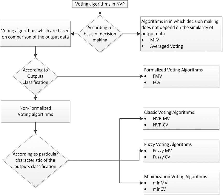
Voting algorithms in NVP.
This study explains how to use NVP in a new way. With NVP, several versions of the same controller will be used for the next action. However, the majority voter can vote to put the system in an unstable configuration (e.g. it could cause an unmanned aerial vehicle (UAV) crash). This study allows the NVP framework to select the input from the minority, which will still result in a stable system, by combining the NVP with an instability detector that marks such inputs as invalid.
NVP-MV algorithm is explained in detail. For a real-time experiment, a tilt-rotor stabilization platform is built, and here, the mathematical model of the system is given. The system has 3 degrees of freedom. Therefore, it can freely move around the roll, pitch, and yaw axes. The platform has proportional–integral–derivative (PID) controllers for each rotation axes. Without loss of generality, the NVP-MV structure is implemented on only roll and pitch controllers. Furthermore, the NVP-MV algorithm is modified by adding a stability checking feature to the system. Experimental results and concluding remarks are discussed at the end of the paper.
N-version programming
The voting algorithms presented in NVP problems are different in dependency on the initial data and the work program. It is crucial to select the most appropriate voting algorithm for a data set. However, the implementation of such algorithms, which require the division of data into subsets of items, is equivalent to each other.1,9,26
In the NVP technique, the architecture consists of N program versions Vj that are independently designed as given in:

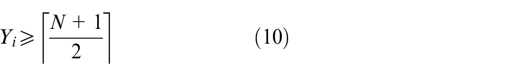
The output of the NVP algorithm is considered to be reliable if at least
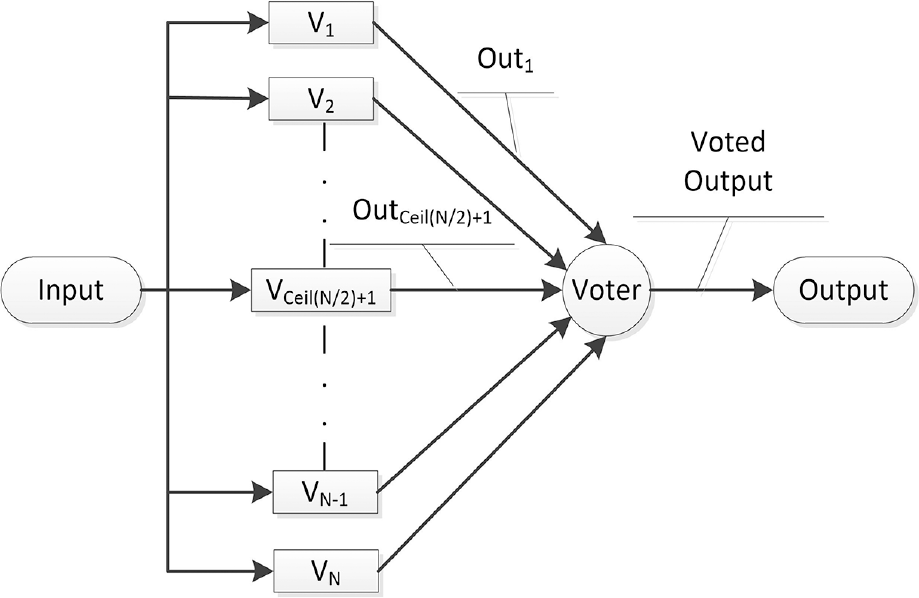
Basic diagram of NVP-MV.
The agreement matrix for NVP-MV
The most critical point in choosing the right set of output is based on the creation and analysis of the so-called agreement matrix
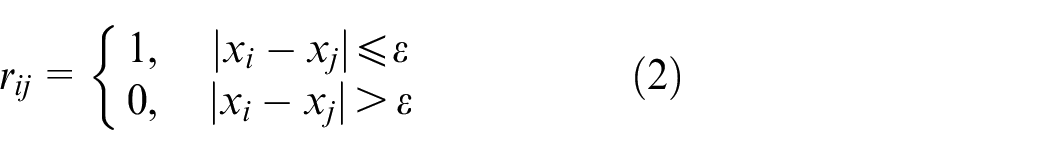
where
The following additional terms apply to the agreement matrix


The purpose of the Boolean compositions on
Given two matrices
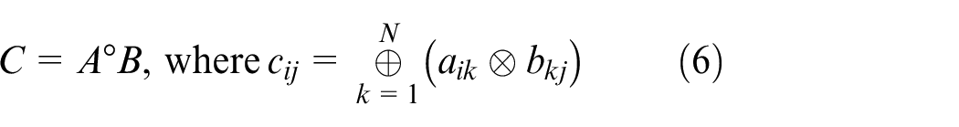
where ⊕ and ⊗ represent the Boolean OR and AND operations, respectively. For the fulfillment of the equivalence relationship (3)–(5) on the agreement matrix

where

the Boolean combination can be rearranged. If the result of equation (8) is still not satisfactory, then the following Boolean combination can be used

The NVP-MV algorithm
Assume that each one of N versions is independent and the output values generated by each version are specified by
Step 1. Build the agreement matrix
Step 2. Analyze the equivalence relation on
Step 3. Equation (7) is carried out until the equivalence ratio (3)–(5) for
Step 4. The correct output set shall be defined. In each row of
then the list of correct results is created from the corresponding units in row
Figure 3 shows the principle how the results of the versions are selected, with
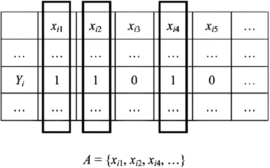
Selection of correct answers from
The tilt-rotor system and the controller structure
The mechanical structure of the system has two main parts. One is a fixed carrier, and the other is dual tilt-rotor system which is mounted on the fixed carrier. The tilt-rotor frame can be freely rotated about three orthogonal axes according to the limitation of the platform. Therefore, the system is 3 degrees of freedom and movable on the roll, pitch, and yaw axes. The tilt system contains brushless direct current (BLDC) and servo motors as actuators. 28 The servos are responsible for yaw and pitch torques, and the BLDC motors are used for roll control. Figure 4 shows the system under control. The mathematical model of the system is nonlinear. In this study, a linear system approximation is performed, which makes the controller design much more comfortable. 29 The controller is chosen to be a PID controller. Any hardware failure of the PID controller causes undesired control signals which will affect the performance or even the stability of the plant. To overcome this problem, an NVP-MV-based structure is considered.
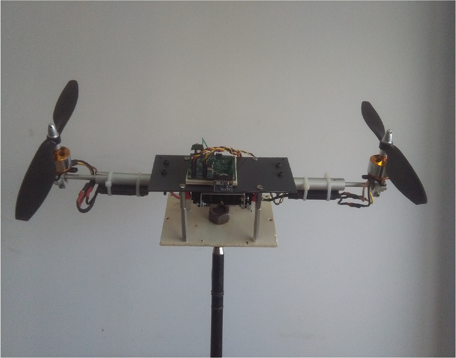
The test system.
Mathematical model
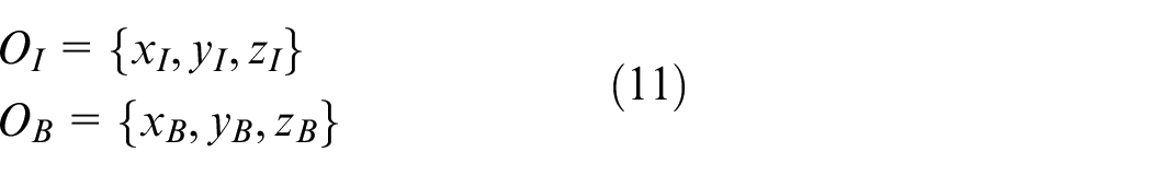
In order to stabilize the system, the roll, pitch, and yaw torques are used. For roll control of the system, the BLDC motor speed difference is used. The servos provide pitch and yaw torques with tilting the BLDC motors and changing the resultant thrust force. For modeling, frames of the platform are defined as follows: the tilt-rotor part is the inertial frame, and the fixed carrier is the body frame. Besides, equation (11) denotes coordinate of the inertial and body frame
Because of the tilt mechanism, the BLDC motors have their own frame. The counter tilting causes yaw torque and represents
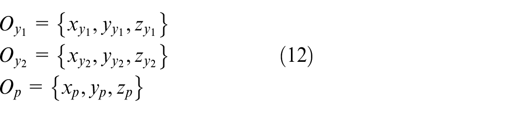
The detailed description of system axes can be seen in Figure 5.
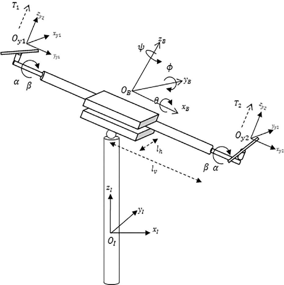
Inertial and body frame of the platform.
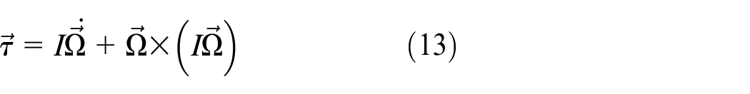
In the equation,

However, in order to reduce the model, the gyroscopic torques, which are produced by tilting, are disregarded. Because of rotational dynamics, the necessary transformation matrices are defined as
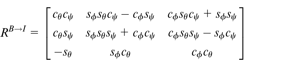
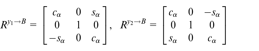
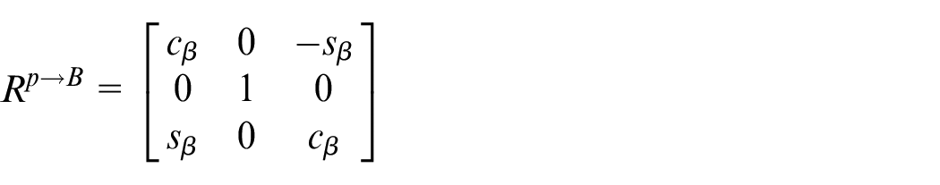
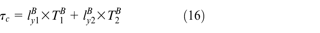
In this context, using the transformation matrices, the force on the center of the body frame can be defined as
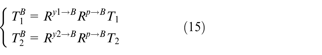
Now, let define the actuator torque
In the equation,
The weight torque is provided by the center of gravity distance on the body frame and defined as

where
So, deriving equations (13), (16), and (17), nonlinear dynamic of the system can be modeled with following equations
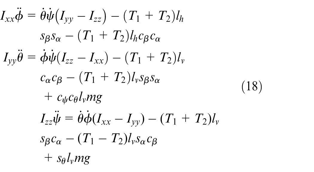
In order to obtain a linear model around the equilibrium point, a linear approximation is applied to the dynamic equations. The roll, pitch, and yaw displacement, and velocities are all equal to zero. So, three subsystems can be defined to provide linear equations. For roll equilibrium, we have
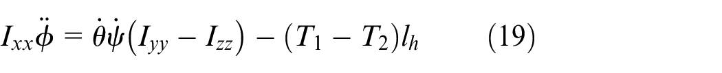
where if control signal is defined as

For the pitch dynamics, assuming

Here, if the control signal is defined as

For the yaw dynamics, assuming
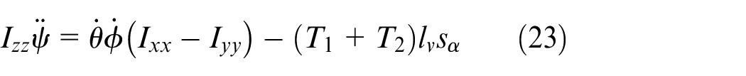
where, if the control signal is defined as

Defining the states of the system

The simplified linear model of the system is as follows
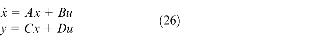
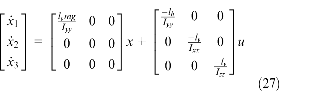
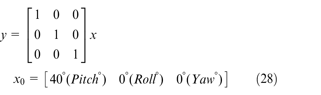
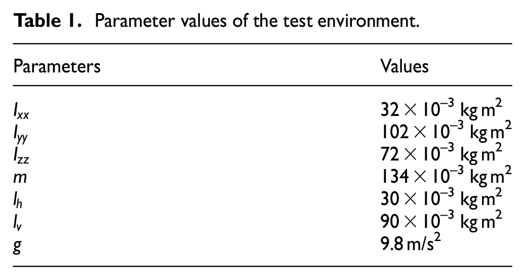
where system parameters are shown in Table 1. The initial states are given below
Parameter values of the test environment.
The linearized model shows that the system can be regulated using low-order controllers such as the PID controller. The controller transfer function is given in equation (29)
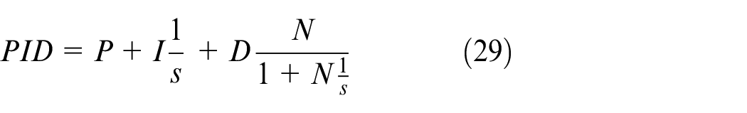
Controller structure
This section will present a real-time controller design procedure for a tilt-rotor UAV based on a modified NVP-MV algorithm. Without loss of generality, we choose the PID controller to meet satisfactory performance and closed-loop stability. Generally, NVP-MV algorithm is a 2 out of 3 structure, which means that, if two versions agree, majority voter takes this decision as the correct output. This general approach is demonstrated in Figure 6.
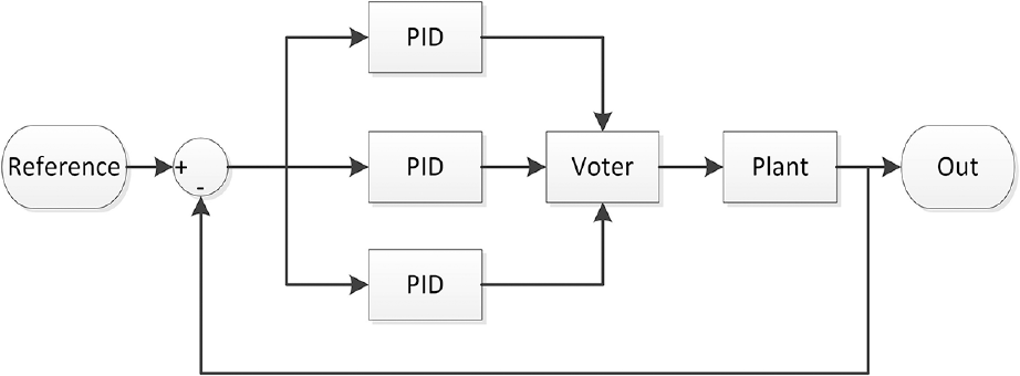
NVP-MV PID controlled system.
In this study, we present an algorithm that makes the voter more intelligent in the sense of detecting stabilizing decisions of the controllers. In this modified voter design, we have implemented an instability detector and a memory which stores the previous decision. So, this type of NVP-MV voter knows whether the decision stabilizes the system or not. A basic block diagram of the novel NVP-MV is demonstrated in Figure 7.
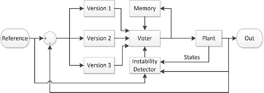
Diagram of designed voter.
Instability detector needs system output value, system states, and reference of the controlled system. The detector output which is the input of the voter is 0 (False) when the system is stable. On the other hand, when the system’s output diverges (unstable), the detector’s output is 1 (True).
Wang et al. 30 proposed that an online Lyapunov stability analysis feature can be integrated to the architecture to achieve a safety-critical controller. This idea influenced the authors of this paper to modify the voter with such a feature, which they call the instability detector.
For input-to-output stability, both the storage and supply functions have to be constructed. Figure 8 shows the principle for

holds, with
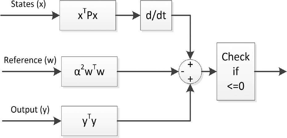
Instability detector.
The proposed modified NVP-MV algorithm is shown in Figure 9.
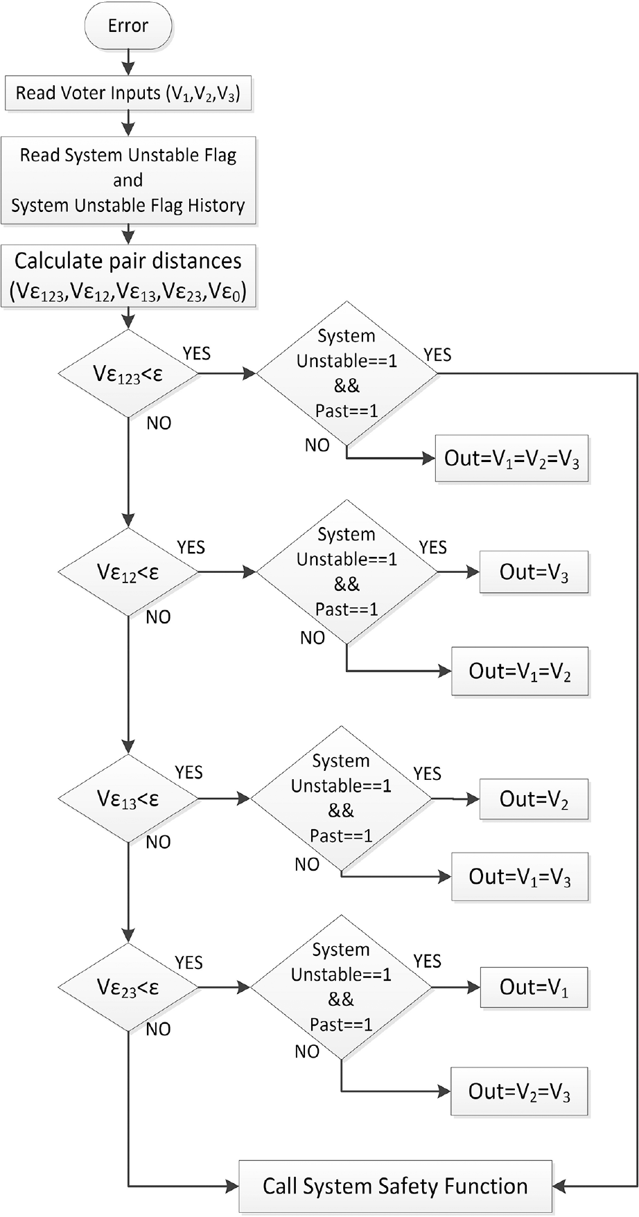
Algorithm of designed voter.
Experimental results
The performance of the proposed modified NVP-MV-based PID controller has been assessed by simulations executed on a tilt-rotor system. This section describes the simulation scenarios and the design of high availability PID controllers. As the simulation environment, MATLAB R2017b Simulink has been used, which is based on real-time behavior and the mathematical model of the system. In the simulation scenario, the system has got three PID controllers for each two states: roll and pitch (yaw behavior is neglected). Each PID controller parameter is calculated using the Ziegler–Nichols method. Recall that the simulation results are not plotted here, because the real-time experimental results are given at the end of this section. The simulation duration is chosen to be 40 s, and every 5 s, one or more of the PID parameters are replaced with such values that make the system unstable. The reason why 5-s intervals are chosen is that the settling time of the system is 3 s for stabilizing controller sets. For PID parameters which make the system stable, the health of PID is defined as 1 (True). Otherwise, PID parameters leading to instability of the system are defined as 0 (False). Table 2 and Figure 10 give information about the simulation details of the scenario, where Figure 10 shows a Markov Diagram to explain the possible states and transitions. Here, common cause effects, the effect that two or three controllers fail at the same time due to a common cause, are neglected.
Simulation scenario.
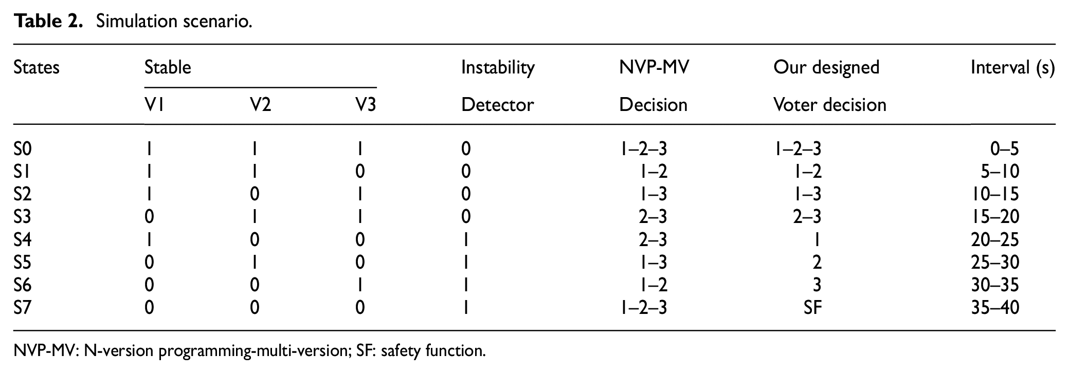
NVP-MV: N-version programming-multi-version; SF: safety function.
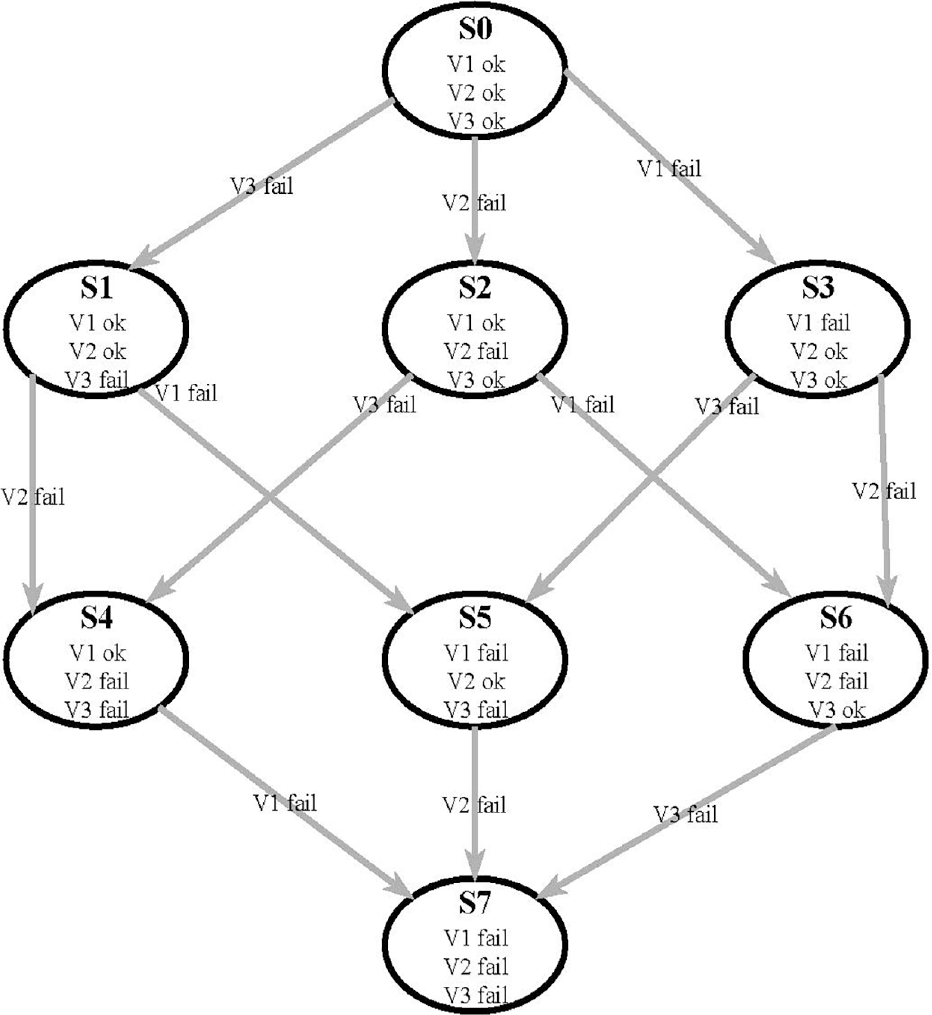
Markov diagram of system.
State S0 indicates that all versions stabilize the system, and
For the real-time experiment, a controller board is build, and a microprocessor is used to implement NVP-MV algorithm. For inertial measurement, 9-degree-of-freedom (DOF) sensor board is added to the controller board. The sensor board has three axes gyroscope, accelerometer, and magnetometer for measuring inertial variations along these axes. The sensor fusion algorithm and the filter are also implemented to increase the reliability of sensor data. In the platform, the servos and BLDCs are controlled by pulse width modulation (PWM) signals.
In the experiment, BLDC’s starting PWM value is 1200 µs and the controllable trust range is defined within 1280 and 1380 µs intervals.
The 1280 µs PWM value is representing the base trust for pitch moving of the platform. Therefore, the PID output of pitch control is set at 0 to 100 intervals. In the same manner, the roll PID output range is settled for −20 to 20. The servos, in the test platform, are settled at its PWM midpoint (1800 µs) for vertical position of BLDCs. The servo PWM operation interval is defined as −50 µs to +50 µs from the midpoint. In this way servos provide ±5 degree tilt angle change for BLDCs. In addition, PID controllers have dead band around equilibrium points.
The NVP-MV algorithm is implemented for roll and pitch PID controllers. Both PID controllers are simultaneously examined with NVP-MV algorithm. Platform stabilization point is arranged as roll and pitch angles equal to zero. Therefore, the PID controller’s desired reference value is also set to zero for roll and pitch. Initially, the system is aligned with zero roll and approximately
In the experiment, three individual PID controllers, which have the same parameters, are designed for roll and pitch controls. PID controller parameters are determined. In addition, PID parameters which can lead to system instability are also determined using the same method (Table 3).
PID parameters.
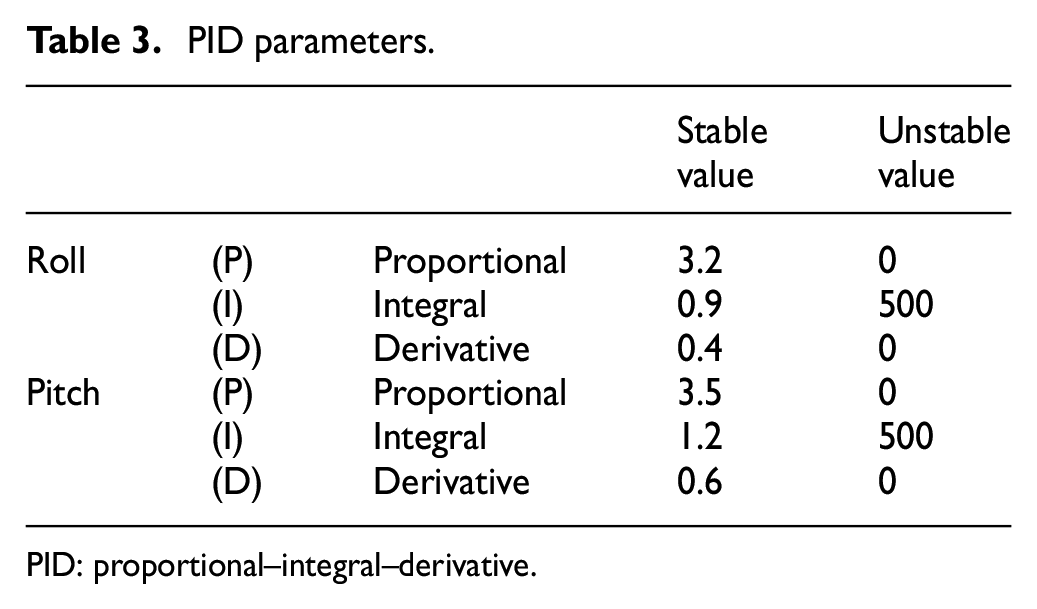
PID: proportional–integral–derivative.
The control board has a frequency of 100 Hz for reading the sensors and calculating the PID outputs. Therefore, the PWM signals of electronic speed controllers (ESC) and servos can be updated every 10 ms. Besides, all system parameters are monitored every 10 ms over a serial interface. Figure 11(a) and (b) shows the roll and pitch response of the system and the corresponding control signals, respectively.
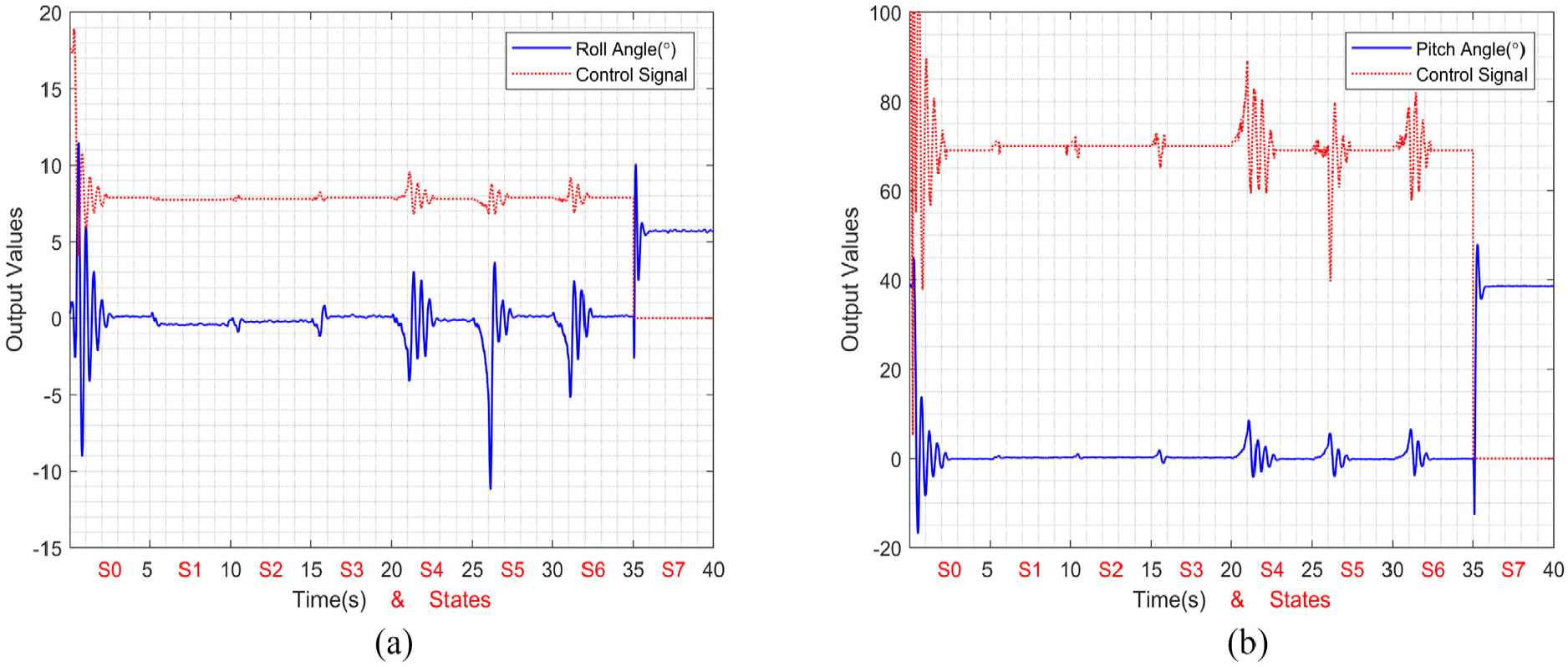
Roll–pitch experimental results: (a) roll response and (b) pitch response.
In Figure 11(a) and (b), the control signal outputs are correlated with PWM input of ESCs and servos. The system output is directly representing the roll and pitch angle of system. For roll control, the roll PID output is added and subtracted from corresponding PWM value of BLDCs. On the other hand, the pitch PID output multiplication with servos’ tilt angle is added ESCs base PWM value, in order to provide necessary trust.
In Figure 11 for state S0 to S3, instability detector outputs are 0 (False), because always two controllers are producing a stabilizing control. S4 state tells us that only Version 1 (PID 1) produces a stabilizing control, and Version 2 (PID 2) and Version 3 (PID 3) make the system unstable; however, since they are the majority, NVP-MV chooses the output of Version 2 and Version 3. Our modified NVP-MV immediately switches to the minority’s decision, which is Version 1. The voter changes the final decision within the next sampling time, which is 0.01 s. Like S4 state, S5 state only Version 2 (PID 2) and S6 state only Version 3 (PID 3) produce a stabilizing control signal which makes the system stable.
In Figure 12(a) and (b), Roll and Pitch instability detectors’ outputs are plotted. For S0, S1, S2, and S3 states, instability detectors output cannot be true because majority voter chooses right pair of controllers. But in the S4, S5, and S6 states, majority voter cannot choose controller which makes the system stable. With the instability detector becoming true, voter changes decision with minority of controllers’ output. If the system is in S7 state, all controller cannot produce a stabilizing control signal and instability detectors output is true. Then the system calls safety function.
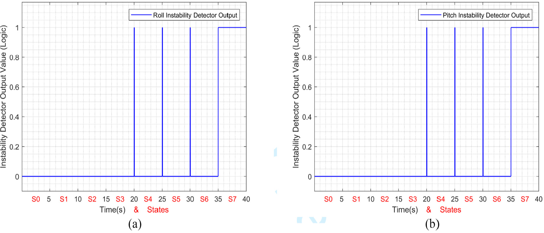
Roll–pitch instability detector outputs: (a) roll instability detector output and (b) pitch instability detector output.
Conclusion and future work
NVP-MV is an effective approach to improve the reliability of a software and it requires an accurate decision of correct and failed versions. In order to do so, using algorithms rating, the correct answer needs to be selected among the set of the plurality of calculation results. Furthermore, NVP-MV is a practical approach to enhance the quality of software for safety-critical applications. However, if the NVP-MV chooses a wrong decision, in other words, the majority is producing a faulty output, then this may lead to instability of the system. In this paper, the NVP-MV is modified in such a way that the voter checks the stability of the system and does not always allow the majority to win if they make the system unstable. The idea is demonstrated on an experimental setup, the tilt-rotor system, and the success of the proposed voter is shown. As a future work, we will study the modified fuzzy voting algorithms and modify the voter further with weighted inputs. Furthermore, we will investigate how the system will benefit from multiple instability detectors where the decisions of instability detectors are also voted.
Footnotes
Acknowledgements
The authors would like to thank all the editors and anonymous reviewers for improving this article.
Declaration of conflicting interests
The author(s) declared no potential conflicts of interest with respect to the research, authorship, and/or publication of this article.
Funding
The author(s) received no financial support for the research, authorship, and/or publication of this article.