
Abstract
This study investigates the influence of twisted tape inserts on a flow pathway in transverse direction of a flow situation. An array of twisted tapes was mounted on the confined channel to disturb the flow to enhance the heat transfer. The test section had 20 twisted tapes of 35-mm height, 10-mm width and a twist angle of 180° mounted on a silica gel–coated plate. Experiments were conducted on the fabricated experimental setup for different discharge conditions. The Reynolds number considered for the study ranged from 2300 to 3500, and the heat inputs varied from 50 to 250 W, with an interval of 50 W. To visualize the presence of twisted tapes on the flow path, the rectangular channel was visualized by laser flow visualization method, which reported the impact of the twisted tapes on the flow. The existence of twisted tape affects the flow, and it forms a swirl that provides a proper mixing of fluid to enhance heat transfer. The outcome of the present investigation provides a solution to enhance heat transfer and proposes the use of twisted tapes instead of using segmented fins in design of fins.
Introduction
Due to the continuous running of equipments in industries, they get heated. It is necessary to cool down these equipments for further usage. Heat exchanger plays a major role in heat reduction in many industries like chemical, food, electronics, refrigeration, petrochemical, automobiles and space applications.1–6 Reduction in the size, less cost, and simplicity are important factors in selection of a heat exchanger. Studies on twisted tapes to enhance the heat transfer have been carried out for the past 10 years.7,8 Experiments using twisted tape placed in transverse direction to the flow to analyze the rate of heat transfer intensification are proposed, and visualization of the flow is done for various Reynolds number.
Fercher and Briersa’s 9 single exposure speckle photography is used to analyze the flow velocity distribution, and spatial filtering techniques are also used to get clear vision on the photograph. Hassan et al.’s 10 outcome says that particle image velocimetry (PIV) is a fast developing technique, and it is an effective tool for the visualization of different patterns and structures in a flow field. Laramee et al. 11 concluded that texture-based flow visualization algorithms were impressive, adroit and suitable for extensive spectrum of applications.
Nanan et al. 12 conducted experiments for twisted tapes with co- and counter swirl helical preparation to analyze the thermal performance, friction factor and heat transfer characteristics. Counter Helical Twisted Tape (C-HTT) exhibits lesser thermal performance factor than Co Helical Twisted Tape (Co-HTT). It is observed that smaller pitch ratio twisted tape shows an elevation in the friction factor and Nusselt number than the thermal performance. Rahul Kumar and Srinivas 13 concluded that decline in twist ratio leads to growth in friction factor. Patil and Vijay Babu 14 experimentally examined twisted tape using four dissimilar twist ratios fitted on a square duct and a circular tube. The outcomes reveal that coefficient of heat transfer and the friction factor rise through the decrease in twist ratio. Heat transfer coefficient was enhanced because of greater surface area and high swirl flow than circular tube. These impose the use of square duct over circular tube.
Yadav et al. 15 analyzed the characteristics of heat transfer rate and friction factor for twisted tape with four diverse twist ratios enclosed in a square and hexagonal duct, and the results were compared with the circular duct. They found that decline in the twist ratio generates good swirl motion, and good mixing leads to better transfer of heat and higher friction factor. Circular duct with a twisted tape of twist ratio 3.5 shows maximum pressure drop. Circular duct shows high Nusselt number and friction factor followed by hexagonal and square duct. Piriyarungrod et al. 16 analyzed three varying twist ratios using tapered twisted tapes with four varying taper angles. The output indicates that tapper angle and twist ratio play a vital role in heat transfer, friction factor and thermal performance. Heat transfer, thermal performance and friction factor rise with reduced twist ratio. It is observed that thermal performance factor enhances with the increase in taper angle. Aldali et al. 17 observed that twist ratio and tape thickness considerably affect the transfer of heat. Further analysis reveals that Nusselt number and friction factor show hikes with the rise in the tape thickness.
Francis et al. 18 found that presence of twisted tape insert raises the transfer of heat by 1.19–2.94 times more than the tube without twisted tape. Sivakumar et al. 19 analyzed the characteristics of rate of heat transfer and friction factor of aluminum and copper twisted tape. They observed that copper twisted tape raises transfer of heat by 1.5%–3% than the aluminum twisted tape and also the copper twisted tape augment fastly in coefficient of heat transfer than aluminum twisted tape.
Jassim et al. 20 analyzed the intensification on heat transfer for twisted tape with four varying twist ratios integrated in a circular pipe. They realized that transfer of heat is enhanced with reduction of twist ratio and transfer of heat was more than the plain tube. Kolhe and Pachgade 21 analyzed rates of heat transfer using twisted tape integrated with concentric double pipe heat exchanger. It was observed that the heat transfer rate increased due to the strong vortex motion developed by the twisted tape. Further observation shows that heat transfer rate and thermal performance factor are high for twist ratio = 5.0.
From the above literature, it was observed that there was no literature which disclosed the impact of the twisted tape in transverse direction of the flow. Reported works used twisted tapes in axial direction of the flow with geometrical effect of the twisted tapes. This research gap induced the spark on further extension of experimental work to study the influence of the twisted tape inserts in transverse direction of the flow.
Experimental setup details and procedure
The pictorial view and schematic view of the experimental setup are shown in Figure 1(a) and (b). The experimental setup consists of a blower of 0.5 HP, hose pipe and 37-mm galvanized iron (GI) pipe which connect the settling chamber and the blower. A 1000-W cartridge heater is equipped in the settling chamber where the air is heated, and hot air flows into the rectangular channel for further investigation. A U tube water manometer is fitted on the flow passage of the air to measure the pressure difference at the inlet and outlet of the orifice meter. A control valve to control and maintain the discharge of the air was provided on the flow pipe.
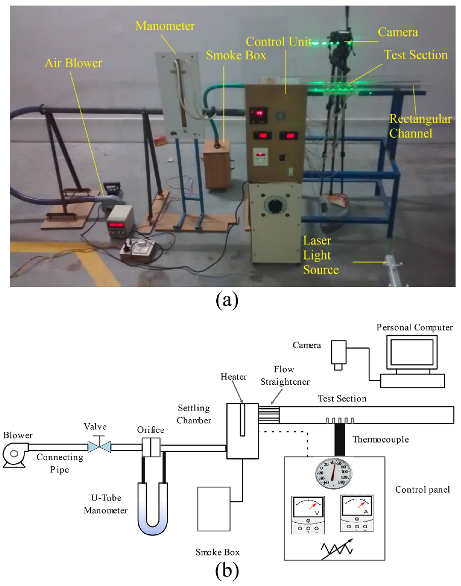
(a) Pictorial view of the experimental setup. (b) Schematic diagram of the experimental set.
The rectangular channel 1000 mm × 70 mm × 60 mm is made of 10-mm acrylic sheet with the test section. At the entrance of the rectangular channel, closely packed straight pipes were provided to make the flow straight and laminar. The twisted tape is fitted in an aluminum plate of size 200 mm × 90 mm × 6 mm, and to ensure the loss of heat in other direction, the plate was insulated properly. Inner surface of the aluminum plate was coated with silicon paste to avoid the absorption of the heat from the hot air. By virtue of this, it was ensured that the heat transfer takes place only from hot air to twisted tapes. The heat absorbed by the coated plate was very minimum, and hence, it was neglected for further investigations during the experimentation.
An array of 4 × 5 twisted tapes as shown in Figure 2 was mounted on the coated plate to form the test section in such a way that they were in transverse direction of the air flow. Twisted tapes were made up of copper strips of thickness 1 mm, and each with height of 35 mm and width of 10 mm with a twist angle of 180°. The test section was mounted on the channel with an upstream section of 250 mm and downstream section of 550 mm to avoid the entrance effect and to ensure the fully developed flow at outlet of the channel. To prevent any heat dissipation and leakage during experiment, a thin layer silica gel is applied on all sides.
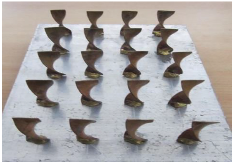
Arrangement of Twisted Tapes.
For flow visualization, laser flow visualization method was used. A green laser of 5 mW was used as a light source, and the light beam was converted into laser sheet to cover the field of view. A digital single-lens reflex (SLR) camera with 200 fps was used to capture the flow visualization images for further processing. To clearly visualize the flow pattern, smoke was allowed to fly through the confined channel. To generate smoke, smoke generator box was provided with the experimental setup, and the flow of smoke also had the same Reynolds number as that of the flow of hot air.
The control unit has Model Selec DTC 303 for temperature control measuring with a full scale accuracy of ±0.25%, Model Selec MV 15 voltmeter ranging 0–480 V with a full scale accuracy of ±0.5%, and ammeter Model Selec MA 12 ranging from 0 to 20 A with a full scale accuracy of ±0.5% and an autotransformer with 230 V, 10 A. K-type thermocouples were used for measuring the temperature with a calibrated accuracy of ±0.1 °C.
Experimental procedure
In the proposed research, working fluid used was air and the properties were considered at 25 °C atmospheric (i.e. density (ρ) is 1.205 kg/m3, specific heat (Cp) is 1005 J/kg K, dynamic viscosity (µ) is 1.81 × 10⁻⁵ kg/m s and thermal conductivity (k) is 0.0259 W/m K). Experimentation was carried out on five different power inputs from 50 to 250 W, with an interval of 50 W. Three different flow rates for each power input were maintained, and the reading was taken until steady-state condition was reached. The outlet velocity of the air was measured with the help of anemometer, to reveal the Reynolds number of the flow.
Initially, for 50-W power input and for the manometer reading of h1 = 20 cm and h2 = 20.5 cm, the temperature at inlet, outlet of the rectangular channel and the temperature of each twisted tape were taken until they reached the steady-state condition. To reach the steady-state condition, it takes 60–75 min depending upon the experimental environmental situations. With the help of temperature sensor, temperature was measured which was mounted on the every twisted tape. To found the Reynolds number of the flow, the flow velocity of air at five different locations of the channel at outlet was measured using anemometer. Once the steady state is reached, the flow visualization process is started and the flow is captured at three different heights of the twisted tapes.
A similar procedure was adopted for rest of the heat inputs and flow rate situations; the temperatures recorded were processed further to calculate the Nusselt number and the coefficient of heat transfer. At steady state, minimum and maximum temperatures reached during the experimentation ranged from 35 to 66 °C and the Reynolds number achieved ranged from 2345 to 3338.
Data reduction
Observed data were used to predict the required quantities using equations (1)–(8). The uncertainties during the experimental investigation were found by Kline and McClintock’s method. 22 Slips for different measures were calculated by the recognized technique of estimation of investigational data. The uncertainties for selected measures from the experimentations were assessed as 2.02% for the Reynolds number, 0.71% for the input heat, 2.09% for the temperature and 2.61% for the coefficient of heat transfer, and for the Nusselt number the uncertainties were found to be 4.32%.
Orifice meter
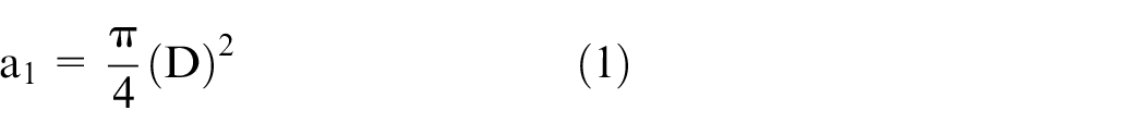
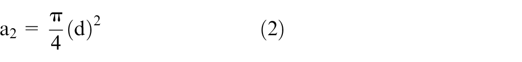
where
Hydraulic diameter
where Dh is hydraulic diameter of the rectangular channel, A is area of the cross section (m2) and P is perimeter (m).
Reynolds number
where V is velocity of the air in the channel (m/s), Dh is hydraulic diameter (m) and
Discharge rate

where Qa is actual discharge (m3/s); Cd is coefficient of discharge, for this experiment; Cd = 0.62 was considered throughout the experiment and Qth is theoretical discharge (m3/s).
Nusselt number
Since it was a non-circular channel and heat was rejected from the fluid, hence for turbulent situation, Dittus–Boelter equation was used to determine the

where Re is Reynolds number and Pr is Prandtl number.
Heat transfer rate

where
Result and discussion
Experiments were conducted as per the procedure stated for three different flow rates, and five different heat inputs ranging from 50 to 250 W. For every flow rate and for every 50 W change in power, the temperatures at inlet and outlet of the channel and temperatures of all the twisted tapes were measured. To ensure the repeatability, the experiments were repeated three times and uncertainties were calculated and reported. 22 Figure 3(a)–(c) depicts the relation between the Reynolds number and the Nusselt number. The flow rate was kept as constant, and the input heat was changed from 100 to 200 W through a variation of 50 W.
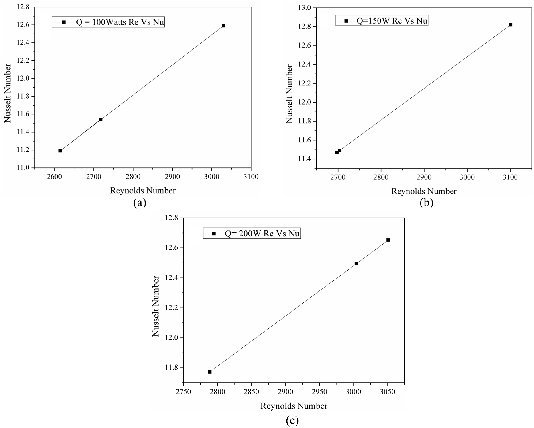
(a) Re versus Nu for
Influence of Reynolds number on Nusselt number
From Figure 3(a), it was keenly witnessed that the Nusselt number was linearly increasing with the rise in Reynolds number. This effect is due to the fact that inertia force overcomes the viscous force by virtue of it there exist a proper recirculation of fluid and ensures the proper interaction of the fluid with the twisted tapes. It is observed that the twisted tapes that first come into contact absorb more heat compared to the rear twisted tapes. This is ensured by the observation of the temperature of the twisted tapes. Similar effect was ensured by increasing the heat input from 100 to 150 and 200 W. It was obvious that while increasing the heat input, the Nusselt number also increases; the same is depicted in Figure 3(b) and (c).
From Figure 3(a)–(c), it can be seen that the increase percentage in Nusselt number was from 42% when compared to 100 W heat input. Similarly, 43% increase in Nusselt number was obtained while changing the heat input from 100 to 200 W. Further increasing the heat input was not having significant influence on heat transfer.
Influence of twisted tape on pressure drop
Figure 4(a)–(c) discloses the relationship between the Reynolds number and pressure drop to show the presence of the twisted tapes on the flow path. Figure 4(a) reports the increase in pressure drop while the difference between h1 and h2 is 5 mm for 100 W. It’s clearly evident that the pressure drop increases with increase in Reynolds number. At Re = 2620, the pressure drop was observed as 48.5911 N/m2, whereas while increasing the flow velocity, it was found to be 145.9925 N/m2. The percentage increase in pressure drop was found to be 66.72%. The pressure tapping were considered at the inlet and outlet of the test section. From Figure 4(b) and (c), a similar trend is observed with increase in pressure drop. The percentage surge in pressure drop ranged from 66.72% to 70% while the heat input increased from 100 to 200 W. This drastic upturn in pressure drop was obtained because of the presence of the twisted tapes on the flow path. This presence influences the flow, and there exists a turbulence of the flow in between the arrays of twisted tapes.
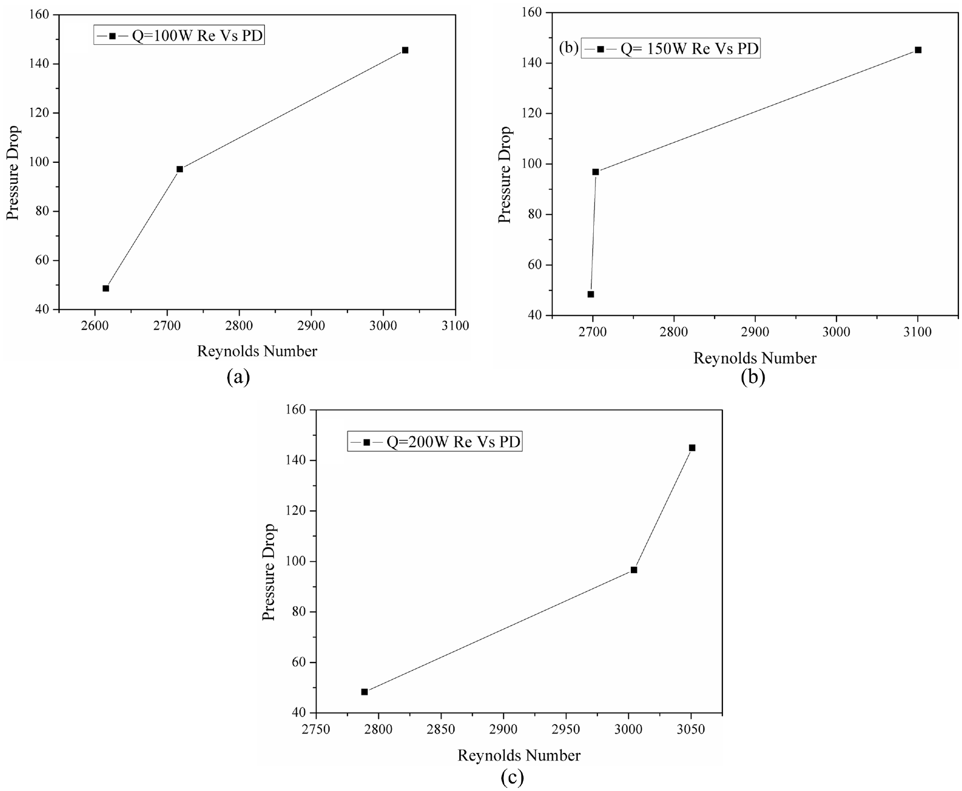
(a) Re versus
Twisted tapes disturb the flow and form swirl flow when the fluid passes the twisted tapes. This formation of swirl reduces the pressure at the downstream of the twisted tapes. The swirl was observed in the flow visualization. This drop in pressure was due to fluid crashing over the twisted tape, and no significant pressure drop was noticed while increasing the heat input. The distance between the twisted tapes on the array was kept constant; hence, there was no significant change in pressure reported while increasing the flow rate.
Influence of heat input on Nusselt number
The impact of heat input on the Nusselt number is reported in Figure 5(a) and (b) for different flow rates whose difference heads range from 5 to 15 mm. Figure 5(a) reveals the relation among the heat input and the Nu. It was predicted that the surge in Nusselt number was obtained by growth in heat input. It’s a fact that the change in Nusselt number was observed due to increase in the heat input; the temperature increases and there exist a huge difference in temperature. This difference in temperature enhances the heat transfer to a significant rate. Identical trend can be witnessed from Figure 5(b), and it was perceived that there was a growth in Nusselt number which increased up to 150-W heat input. A rapid increase was detected between 150 and 200-W heat input due to the influence of the twisted tape.
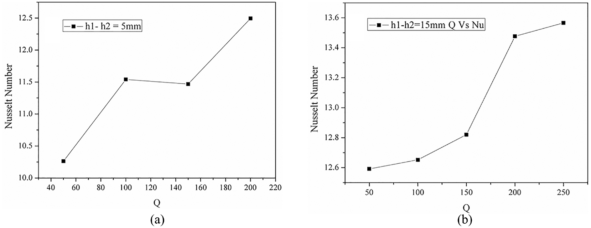
(a) Heat input versus Nu for
Flow visualization
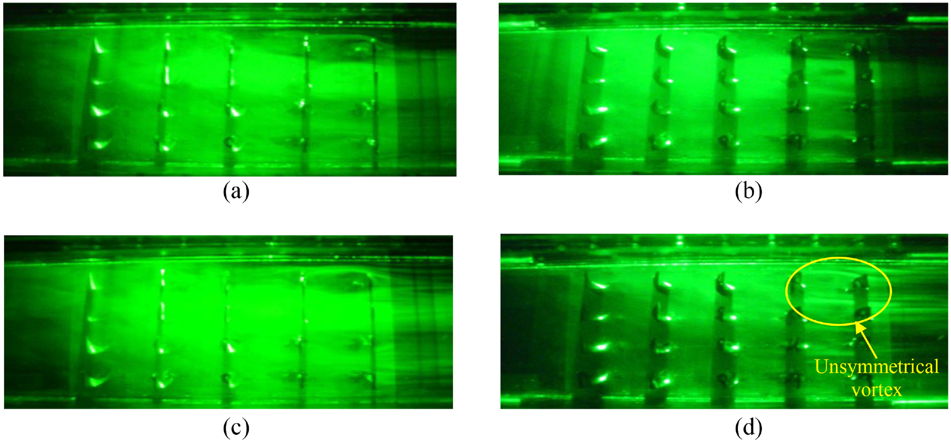
The flow was visualized by laser flow visualization method to understand the existence of twisted tapes on the transverse flow path. A green laser light source of 5-mW power was used to generate the laser sheet to cover the entire flow region. A SLR digital camera of 200 fps was used to acquire the video of the flow situation. By further processing, the video was converted into images and reported. Videos at different heights of the twisted tape were recorded to study the influence of twisted tape on the flow pattern. To enhance the visualization, smoke was generated and allowed to flow through the confined channel. Keen observations were made to ensure the flow of smoke and air having the same flow velocities. The flow patterns at 10-mm height of the twisted tape were recorded and reported as image in Figure 6(a). It was evident that the flow patterns were prominently disturbed by the twisted tapes. At this 10-m height from the bottom of the twisted tape, the flow pattern was observed as two unsymmetrical vortexes developed on the downstream side of the twisted tape which is marked in Figure 6(a); during this, the Reynolds number was maintained as Re = 2345. This can be viewed clearly with a camera of greater than 1000 fps. These unsymmetrical vortexes were formed due to the impingement of fluid on the twisted tape surface. At this stage, the twisted tape twist angle may be 35° transverse to the flow direction.
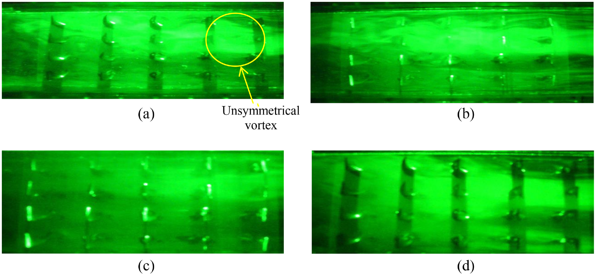
(a and b) Re = 2345 and Q = 100 W at 10-mm height of the twisted tapes. (c and d) Re = 3000 and Q = 100 W at 10-mm height of the twisted tapes.
From Figure 6(c) and (d), at Reynolds number Re = 3000, the flow patterns observed was at 10-mm height of the twisted tapes. Since the Reynolds number was high, visualizing the flow pattern required a camera with a higher frame rate. From these images, it was evident that the flow was highly influenced by the presence of the twisted tapes.
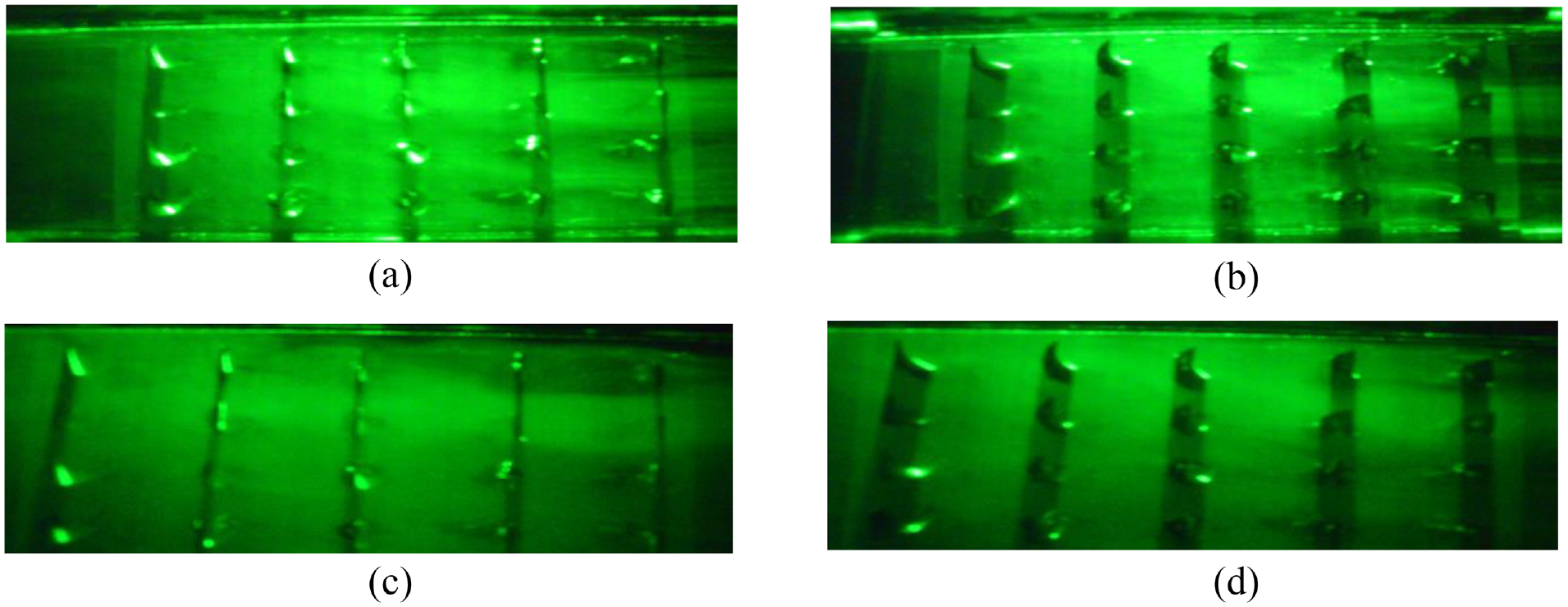
From Figure 7(a)–(d), it was observed that the flow was visualized at Reynolds numbers Re = 2637 and Re = 3338 for 100-W heat inputs. It was clearly visible that there was no such significant disturbance noticed on the flow patterns at 17.5-mm height of the twisted tapes. At this height, the twisted tape was parallel to the flow direction. At this section, the flow was not much disturbed by the twisted tape. The flow was separated into two by the presence of the twisted tape since the thickness considered for the study was 1 mm.
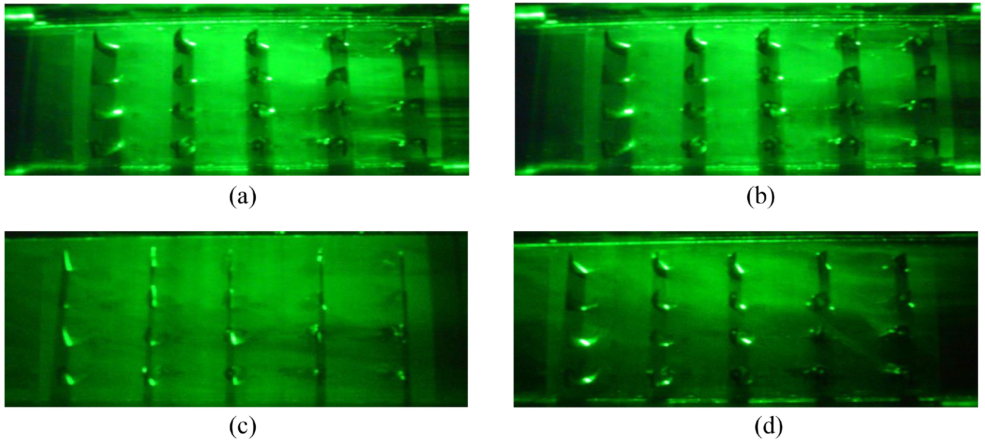
(a and b) Re = 2637 and Q = 100 W at 17.5-mm height of the twisted tapes. (c and d) Re = 3338 and Q = 100 W at 17.5-mm height of the twisted tapes.
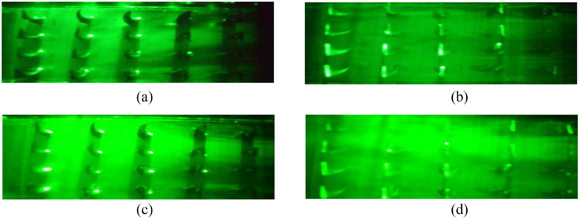
The flow visualizations at 25-mm height from the bottom of the twisted tape for Reynolds numbers Re = 2703 and Re = 2788 is shown in Figure 8(a)–(d), respectively. From these images, it was apparent that the flow patterns were still disturbed by the twisted tape provided on the flow path. The flow pattern observed was in reverse to the flow pattern obtained at 10-mm height of the twisted tape. Unsymmetrical vortexes were observed downstream side of the twisted tape. At higher Reynolds numbers, it was little difficult to observe the flow pattern unless otherwise a high-end frame rate camera was implemented.
(a and b) Re = 2703 and Q = 100 W at 25-mm height of the twisted tapes. (c and d) Re = 2788 and Q = 100 W at 25-mm height of the twisted tapes.
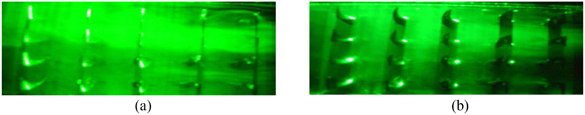
Figure 9(a)–(d) depicts the flow visualization at 10-mm distance of the twisted tape from bottom for Reynolds number Re = 2654 and Re = 3030 at for 200-W heat input. Alike trend was witnessed in these images when compared to the images taken at 10-mm height for 100-W heat inputs. There were no such significant changes obtained on flow pattern while changing the heat inputs. This was due to the constant distance between the arrays of twisted tapes fixed on the flow path in transverse direction of the flow.
(a and b) Re = 2654 and Q = 200 W at 10-mm height of the twisted tapes. (c and d) Re = 3030 and Q = 200 W at 10-mm height of the twisted tapes.
Figure 10(a)–(d) discloses the flow patterns observed at Q = 200 W and Reynolds number Re = 3100 at 25 mm from the bottom of the twisted tape. Here also, no such commendable flow patterns disturbance was recorded similar to the previous situation for 100-W heat input. Figure 11(a) and (b) shows the flow patterns visualized at the top of the twisted tape. To know the impact of the twisted tape at the free end, video was captured to record the fluctuations in flow patterns. Surprisingly, there was no great impact of the twisted tapes on the flow patterns above the top of the twisted tapes. It was expected that due to the downstream side effects of the twisted tapes, there might be a chance for influence of the flow pattern at the top. No such significant disturbances were recorded on the top surface of the twisted tape. A layer of laser sheet was visualized at Reynolds number Re = 3331 at a height of 40 mm from the bottom of the twisted tape.
Re = 3100 and Q = 200 W at 25-mm height of the twisted tapes.
Flow visualization at Re = 3331 and Q = 100 W at 40 mm from the bottom of the twisted tape.
Conclusion
Experimental analysis on heat transfer augmentation to report the influence of the twisted tape provided on the transverse direction of the flow in a confined channel was conducted, and the following conclusion was reported. Air was used as flowing medium for the entire study. The Reynolds number considered for the experiments ranged from 2300 to 3500 and heat inputs from 50 to 250 W for three different flow rates of the air.
From the experimentation, it was resolved that the availability of the twisted tape on the flow path in transverse direction of the flow was having a high impact on the flow patterns.
The growth in Nusselt number was predicted as 63% when compared to the low heat inputs.
Escalation in Re leads to the rise in the Nusselt number and shows a significant influence of the twisted tapes.
Flow visualizations were recorded and reported for various Reynolds numbers and heat inputs. The presence of the twisted tapes on the transverse direction of the flow seriously affects the flow pattern.
It also shows that the rate of heat transfer increases with increasing rate of flow and power input.
Footnotes
Declaration of conflicting interests
The author(s) declared no potential conflicts of interest with respect to the research, authorship, and/or publication of this article.
Funding
The author(s) received no financial support for the research, authorship, and/or publication of this article.