
Abstract
Traditionally, successive approximation method is applied to the vibration-level adjustment of vibration calibration system, which leads to a time-consuming work for low-frequency vibration calibration. In this paper, a novel control method for low-frequency vibration calibration system is proposed based on adaptive filter. First, the problem of the traditional vibration-level adjustment for low-frequency signals is depicted. Then, an adaptive control algorithm is presented, in which the control input is composed of two weighted sinusoidal signals with a phase difference of 90°. The weighted vector is updated in real time using a modified filtered-x least mean square algorithm. Unlike filtered-x least mean square algorithm, the proposed modified filtered-x least mean square algorithm does not require a pre-identification of the controlled system and has a reduced computational complexity. The convergence property of the proposed method is analyzed in detail. Finally, the proposed method is implemented on a low-frequency vibration calibration system. Experimental results show that the proposed modified filtered-x least mean square algorithm can significantly reduce the time of the vibration-level adjustment in low-frequency band.
Keywords
Introduction
Vibration calibration systems are of great importance for accurate measurement of vibration sensors. Nowadays, many vibration sensors are required to have a low-frequency range below 1 Hz in applications like the measurement of building, bridge and seismic activities and so on, which brings more attention to the development of low-frequency vibration calibration systems.1–3
In order to facilitate the calibration process for various sensors, the vibration generated by the shaker is required to track the desired level precisely. A successive approximation method (SAM) is traditionally widely used for vibration-level adjustment. 4 In this method, the external input voltage is continually corrected step by step based on the deviations between the desired level and measured level until the tolerance is satisfied. The measured vibration level is determined usually by the collected signals of a standard sensor with several periods. Thus, the vibration-level adjustment for low-frequency calibration is often a time-consuming process, 5 which is mainly caused by slow peak detection due to the long period of low-frequency signals.
Aiming at shortening the time for vibration calibration, He and collegues6,7 proposed a frequency-shift method, in which the vibration level is pre-adjusted to the desired level at a higher frequency and then the frequency of the input voltage is gradually decreased to the desired level. However, this method is based on the assumption that the closed-loop frequency response in the low-frequency part is constant, which can only be satisfied with pure displacement feedback control. The adjustment method is still essentially SAM. Another approach based on expert system was also applied in vibration-level adjustment, 8 which requires a measurement of output vibration level as well.
Actually, the primary drawback of SAM is the fact that the vibration-level measurement requires at least one period. Some other approaches like least square algorithm 9 and tracking filter method10–12 can realize accurate amplitude estimation with fewer sampling points. Unfortunately, these approaches will increase the computational efforts significantly. Worse still, they give rise to the possibility of instability since the accurate measurement of the instant amplitude is not likely to be obtained due to the updating of input voltage frame by frame.
Filtered-x least mean square (FxLMS) algorithms in both time and frequency domain have been widely used in active noise control (ANC) problems.13,14 A time-domain narrowband FxLMS algorithm can offer an efficient and precise vibration-level tracking in vibration calibration systems. The FxLMS algorithm is free of vibration-level measurement, in which the input voltage is being updated in each sampling point according to the current deviation between the measured time-domain signals and the desired signals. However, the drawback of the FxLMS algorithm mainly lies in that a pre-modeling of the controlled system must be available, which is called secondary path modeling in ANC systems. The modeling is commonly realized by finite impulse response (FIR) filter in offline identification, which is inconvenient and time-consuming especially when some changes occur in the controlled system. The modeling phase error must be within 90° for the sake of convergence. 15 Hence, the FIR filter for modeling is required to have sufficient length in order to get an accurate modeling, which increases computational efforts.
There have been many modifications of the FxLMS algorithms reported in recent decades. In FxLMS, a high-order filter will introduce delays in the error signal, which decrease the convergence. A modified form of the FxLMS algorithm was proposed by Bjarnason 16 to improve convergence speed. Simplified algorithms of modified FxLMS were also presented17,18 to save complexity, but they are still more complicated than FxLMS. More importantly, an accurate prior modeling must be provided like FxLMS.
Some other modified FxLMS algorithms have also been proposed for improvement in online identification in ANC systems.19,20 Unfortunately, an additive noise must be introduced for online identification, which will seriously affect control precision. Recently, several ANC methods without secondary path modeling have been presented.21–23 However, they have more computational complexity and slower convergence rate than FxLMS.
In this paper, a novel adaptive control method for vibration calibration system is proposed based on another newly modified filtered-x least mean square (MFxLMS) algorithm. In the MFxLMS algorithm, the high-order FIR filter used in modeling is reduced to two online identified parameters. The adaptive law is derived and convergence properties are analyzed in detail. Compared to the FxLMS algorithm, the MFxLMS algorithm has the merits of much lower computational complexity and elimination of the need for offline identification. In addition, this method can achieve a much faster adjustment in low-frequency control compared with the traditional SAM.
Problem formulation
The construction of the low-frequency vibration exciter with a permanent magnet we developed is shown in Figure 1. When an external input voltage acts on the moving coil, the vertical motion of the moving mass can be driven by Ampere force induced by the magnetic field. The maglev coil is connected with direct current in order to offset the weight of the moving components. A grating displacement transducer is used to measure the motion of the moving mass. The open-loop input–output relationship of the system can be described as a three-order transfer function. 7
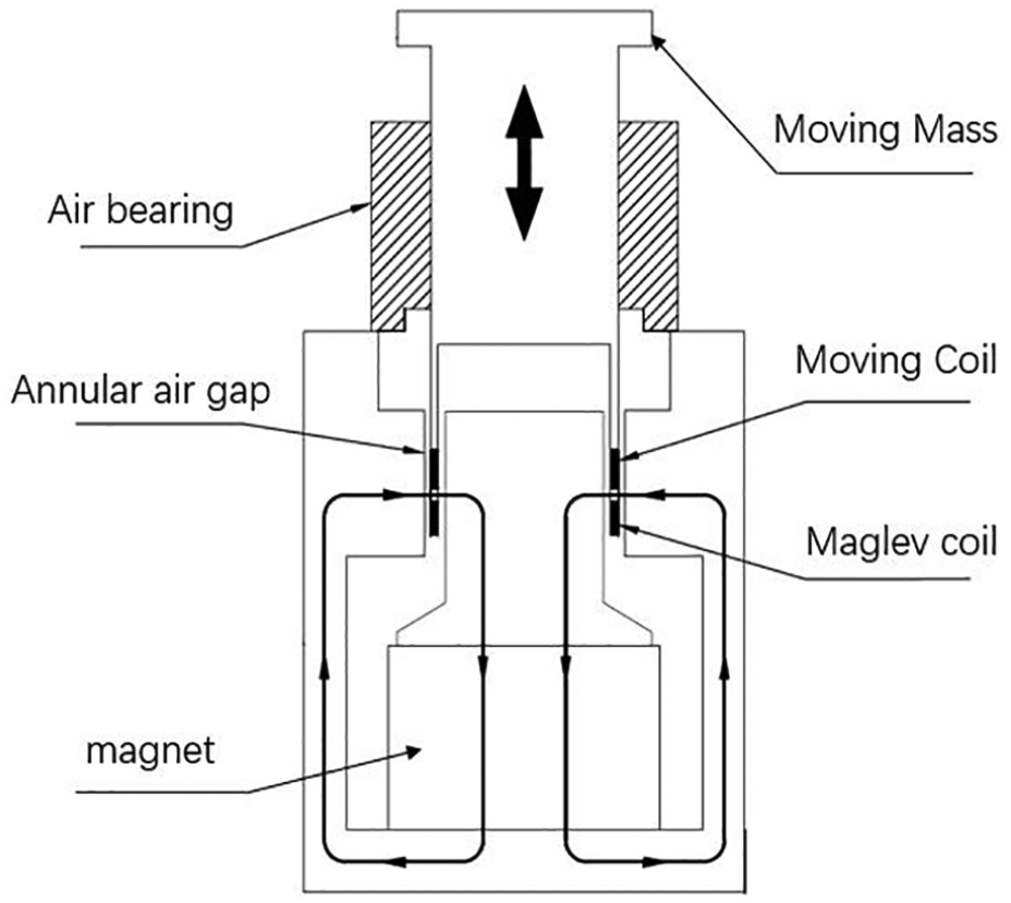
Construction of low-frequency vibration exciter.
In order to partly suppress distortion induced by nonlinear factors of the system, proportional–integral–derivative (PID) feedback controller is adopted. Thus, the whole transfer function in closed loop becomes more complex, which involves both the PID coefficients and the system parameters. Due to the unknown system parameters, the system frequency response depicting the relationship of the output vibration level and the input voltage amplitude cannot be predicted. Hence, in traditional SAM, the vibration level is adjusted according to the measured peak value of the output displacement. Assuming that
In the first measurement frame, the initial amplitude of input voltage is
in which the subscript k represents the kth frame.
The ideal incremental voltage is

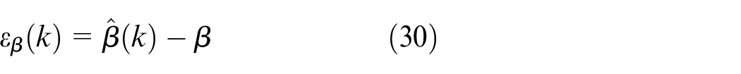
Considering the nonlinearity of the system, a correction factor

If the measurement frame is set as

in which
It is worth noting that the time-domain input voltage must be corrected continuously point by point within each frame in order to prevent a impact on the vibration exciter.
Adaptive control algorithm
The FxLMS algorithm
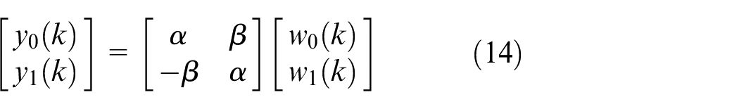
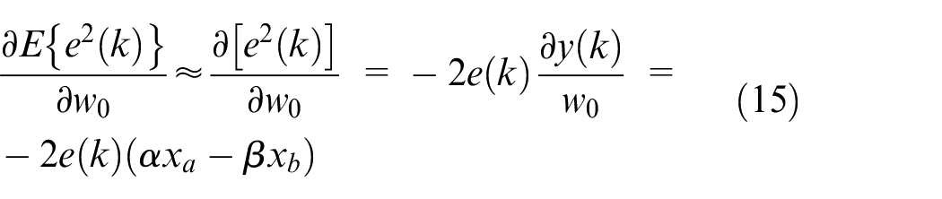
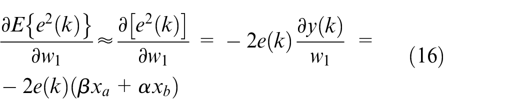
In the proposed adaptive control algorithm, the input voltage is composed of two weighed sinusoidal signals, which is given by


where
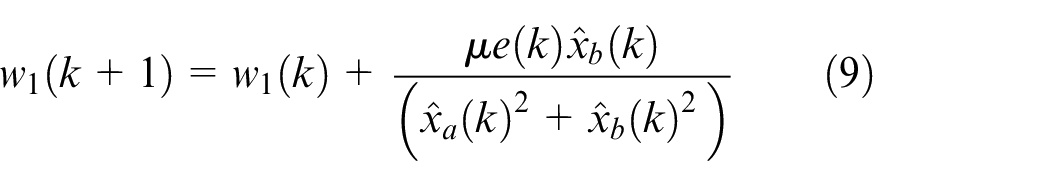
where

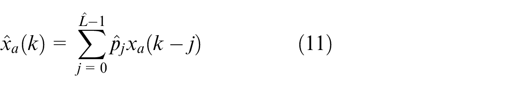
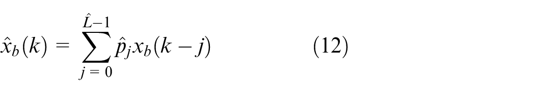
and
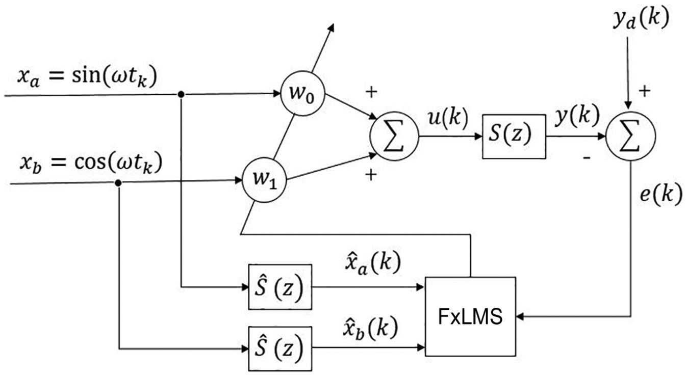
Block diagram of the FxLMS algorithm.
As formulae (11) and (12) imply, a prior knowledge of
Derivation of the MFxLMS algorithm
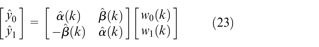
With the assumption of linear system, the output displacement can be given by

where
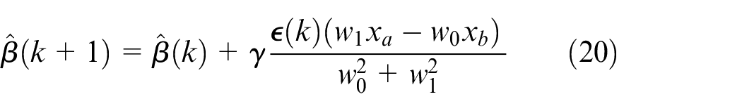
Suppose that one substitutes the least square error with the instantaneous error. Hence, using the gradient optimization method, a simpler updating algorithm for


where the step size
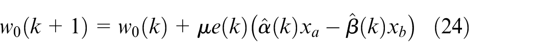
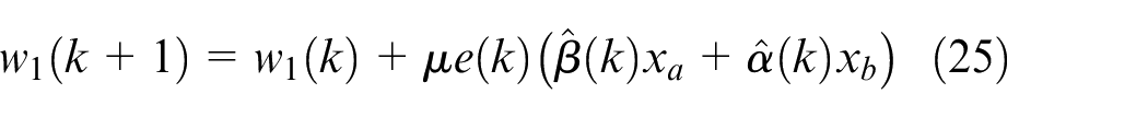
Now, the problem is to determine the values of parameters
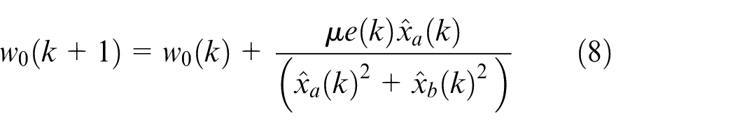
Using the normalized least mean square (NLMS) algorithm, 13 the online identification algorithm can be easily derived as follows
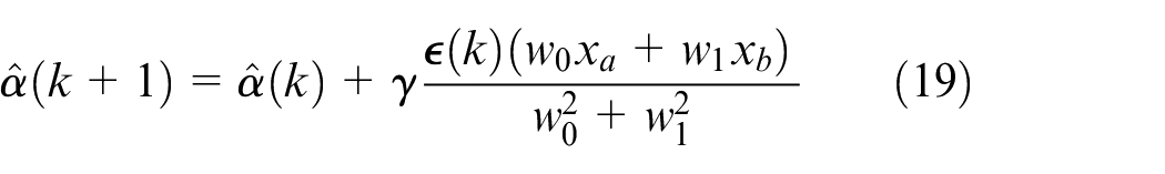


where
As a summary, the block diagram of the MFxLMS algorithm is shown in Figure 3.
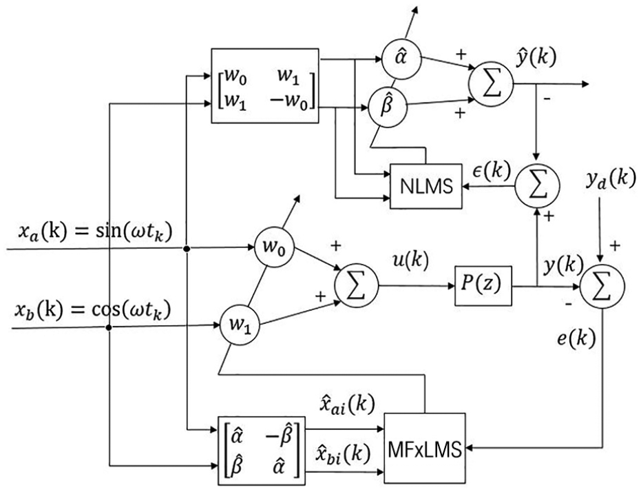
Block diagram of the MFxLMS algorithm.
Comparison of efficiency and computational cost
The comparison of computation cost in one time instant between FxLMS and MFxLMS algorithms is presented in Table 1. Due to the fact that the controlled plant
Comparison of computational cost between FxLMS and MFxLMS algorithms.
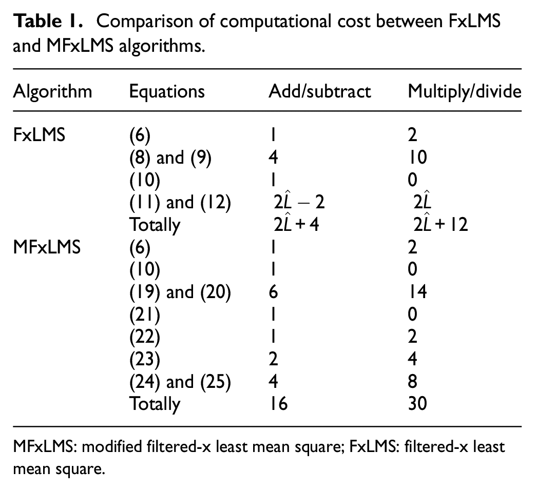
MFxLMS: modified filtered-x least mean square; FxLMS: filtered-x least mean square.
Convergence analysis
Widrow et al. 29 have investigated the convergence characteristics of the LMS algorithm, the conclusion of which can be readily extended for the convergence analysis of the FxLMS algorithm. 30 The stochastic properties of the broadband and narrowband FxLMS algorithm have also been analyzed in Bjarnason, 31 Tobias et al. 32 and Xiao et al. 33 However, the convergence of the modified algorithm proposed in this paper has not been studied yet. Here, the convergence performances of the proposed algorithm are discussed in the sense of ensemble average.
Convergence in mean sense
For a vibration calibration system, the desired reference signal is sinusoidal, which can be given by

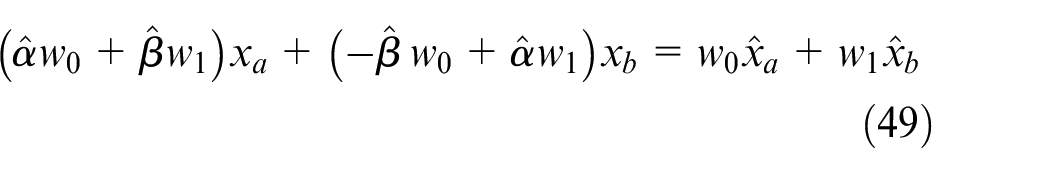
where
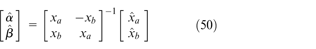
For minimizing
Define the parameter identification errors as

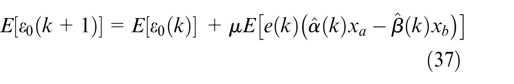
Then subtracting
where
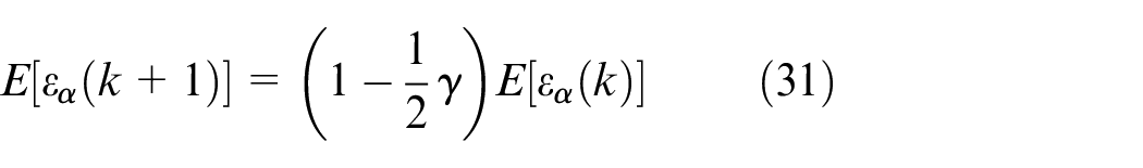
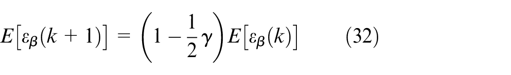
Now, from the difference equations (31) and (32), it can be concluded that the transient performance of

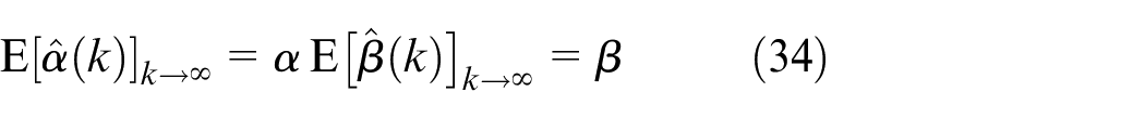
That is to say, the identified parameters will eventually converge to their true values
Define the weight errors as


Subtracting
It has been derived from equations (31) and (32) that
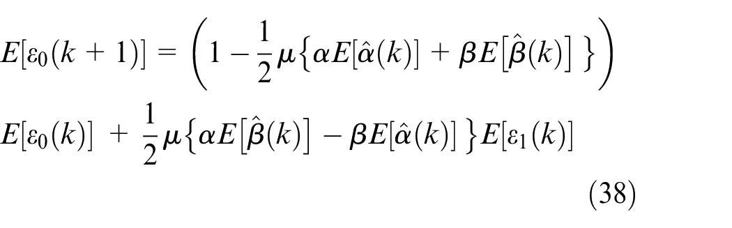
Similarly, subtracting
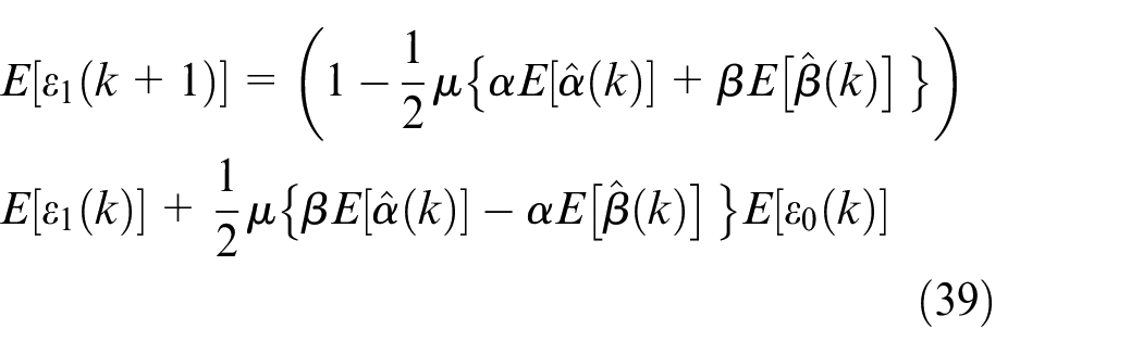
When the steady state is reached, using equation (34) in equations (38) and (39), the second terms on the right sides of equations (38) and (39) become zero. This indicates that the convergence process of
Stability bound in mean sense
Regarding the transient performance of the proposed algorithm, the difference equations (38) and (39) are multivariable coupled linear equations for
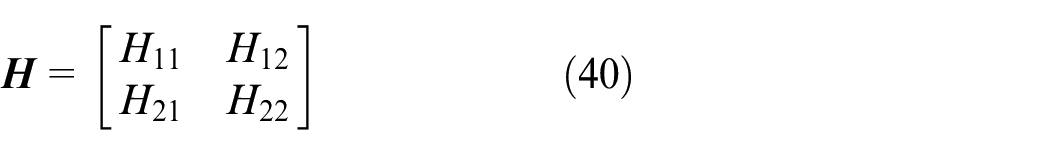
where
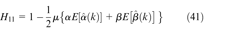
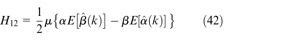
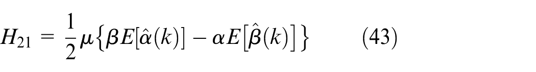
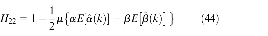
The convergence condition can be obtained as

where
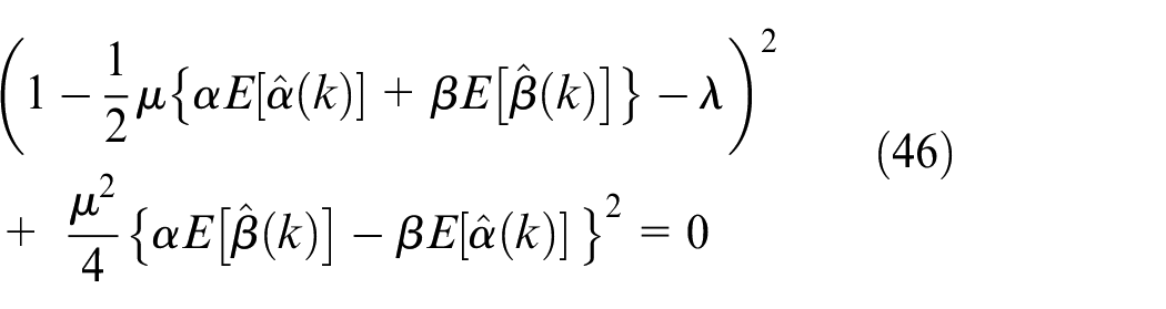
Obviously, the two eigenvalues
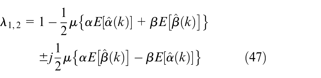
where
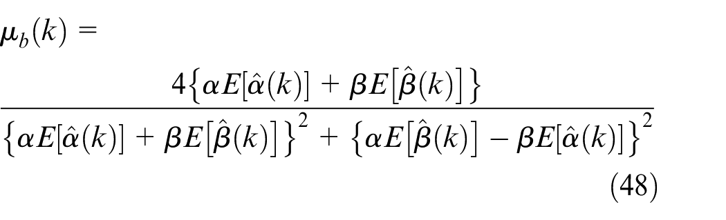
It should be noted that equation (48) just gives the convergence condition in mean sense, which cannot guarantee convergence in mean square. The mean square properties can be described as a set of complex nonlinear equations, the convergence condition of which cannot be readily obtained. On the contrary, the assumption of equation (14) may not be satisfied perfectly when the step size is large enough, which also gives rise to the possibility of divergence. Hence, in practical use, the bound of step size in equation (48) is indeed insufficient for convergence. Nevertheless, it can appear as a reference for adjusting the step size. It can also be concluded that the step size should be relatively small for the sake of convergence when estimated
Experimental results
In order to show the efficacy of the MFxLMS algorithm, experiments based on a low-frequency vibration calibration system have been conducted using the algorithm presented in section “Adaptive control algorithm.” The experimental system is set up as shown in Figure 4. In the system, a displacement sensor is mounted on the moving parts of the shaker. The displacement data are acquired by the input channel of the digital signal processing–based (DSP-based) controller. The output of the controller is connected to a power amplifier which drives the moving parts to move. The PID control technique is adopted to form a closed control loop for reducing the harmonic distortion. The sampling period
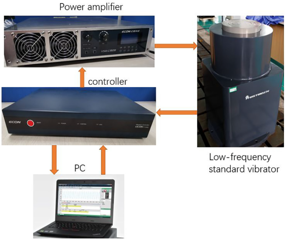
Experimental setup of the low-frequency vibration calibration system.
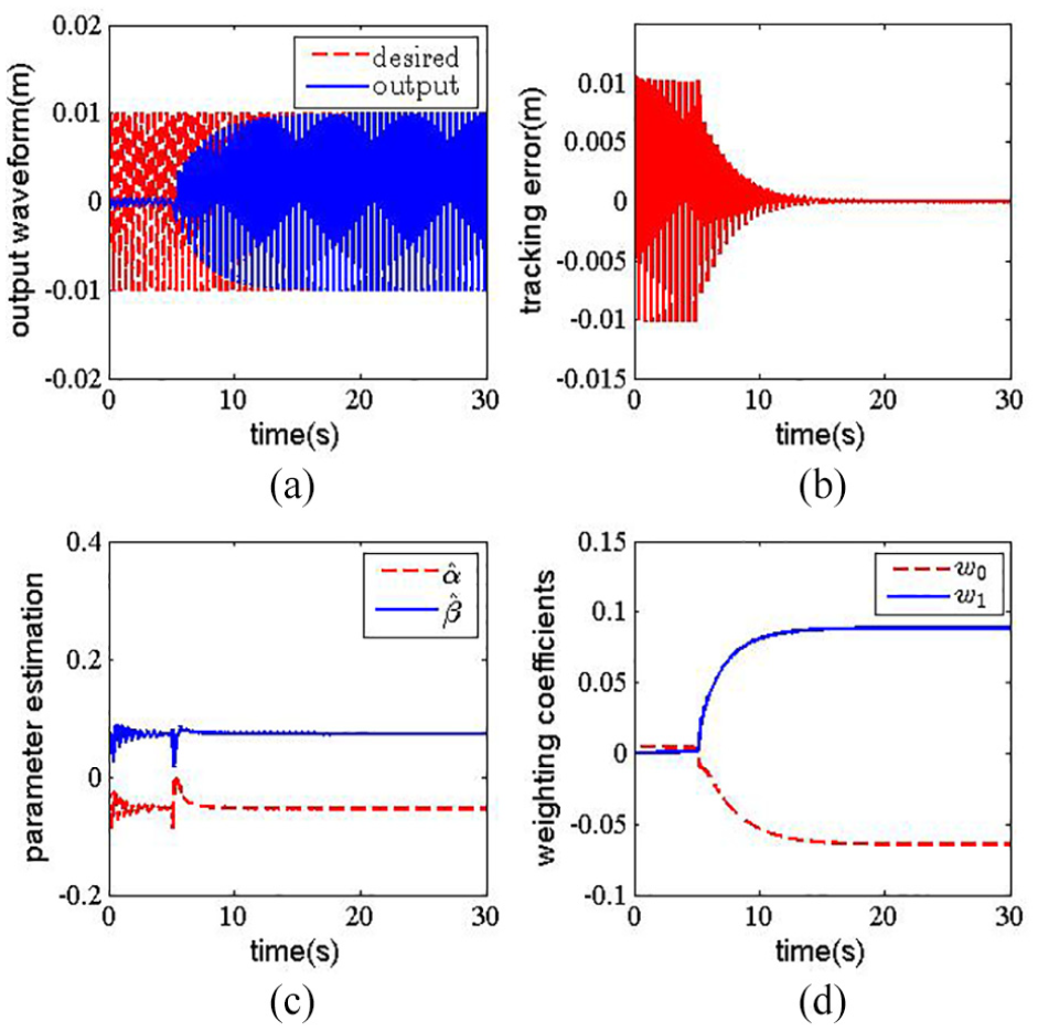
Regarding the PID control as the inner loop, the MFxLMS algorithm is implemented on a DSP-based controller. Several typical frequencies 0.05, 0.1, 0.5, 1 and 2 Hz are selected to validate the performance of the two methods. The experimental results of the five frequencies are presented in Figures 5–9, respectively. In all the experiments, the initial parameters are set as
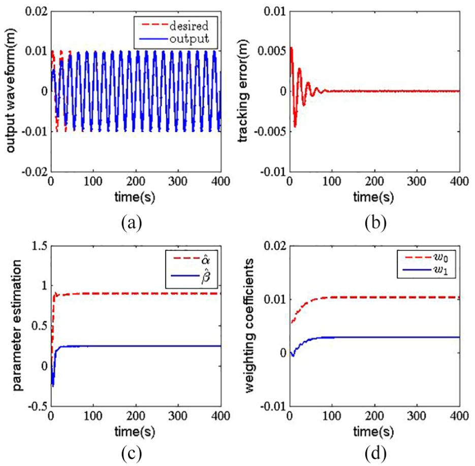
Experimental results at 0.05 Hz on a low-frequency vibration calibration system: (a) output waveform profile
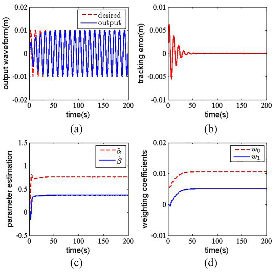
Experimental results at 0.1 Hz on a low-frequency vibration calibration system: (a) output waveform profile
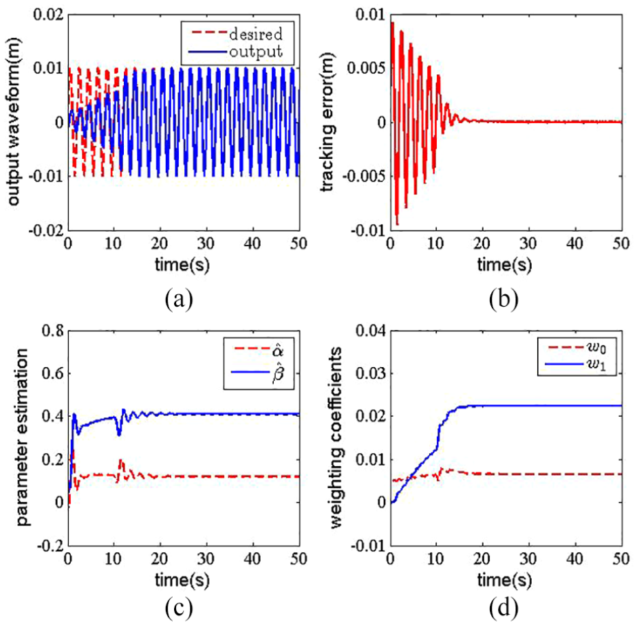
Experimental results at 0.5 Hz on a low-frequency vibration calibration system: (a) output waveform profile
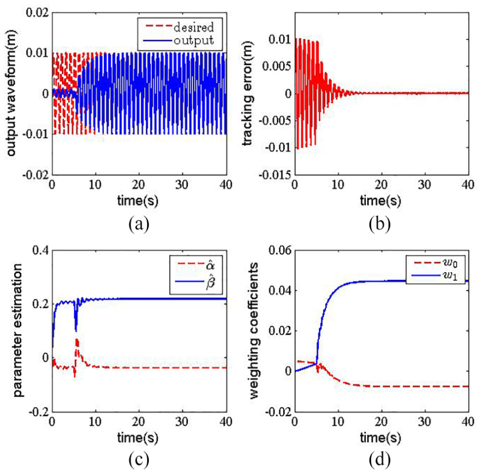
Experimental results at 1 Hz on a low-frequency vibration calibration system: (a) output waveform profile
Experimental results at 2 Hz on a low-frequency vibration calibration system: (a) output waveform profile
It can be seen from Figure 5 that at a frequency of 0.05 Hz, the parameter estimation and the weighting coefficients converge to their respective values eventually. The tracking error converges to zero eventually. The output waveform has tracked the desired waveform perfectly within five periods. It can also be seen in Figures 6–9 that the output waveform tracks the desired waveform and all the parameters converge eventually at frequencies of 0.1, 0.5, 1 and 2 Hz. However, when the frequency increases, it needs more period to adjust to the desired level.
Table 2 presents the comparative results of adjustment time at these different frequencies using MFxLMS, FxLMS and SAM. The code of the proposed MFxLMS has been uploaded in https://github.com/chaodongZJU/LF. It can be seen in Table 2 that the convergence of the FxLMS algorithm is slightly faster than MFxLMS. The main reason is that the FxLMS algorithm has a pre-identified modeling, which is unknown in MFxLMS. In the frequency band less than 1, the adjustment time by the MFxLMS algorithm is much less than that of SAM. However, when the frequency increases, it seems to have no obvious advantage of the MFxLMS algorithm compared with SAM. The MFxLMS algorithm behaves even worse than SAM at 2 Hz. It can be further concluded that in the low-frequency band, the MFxLMS algorithm behaves significantly better in adjustment speed than SAM. However, when the frequency is over 1 Hz, it is better to employ the traditional SAM. The improvement in adjustment speed by the proposed MFxLMS algorithm is extraordinarily meaningful, since the adjustment time is exceedingly longer in the low-frequency band.
Comparative results of vibration-level adjustment time.
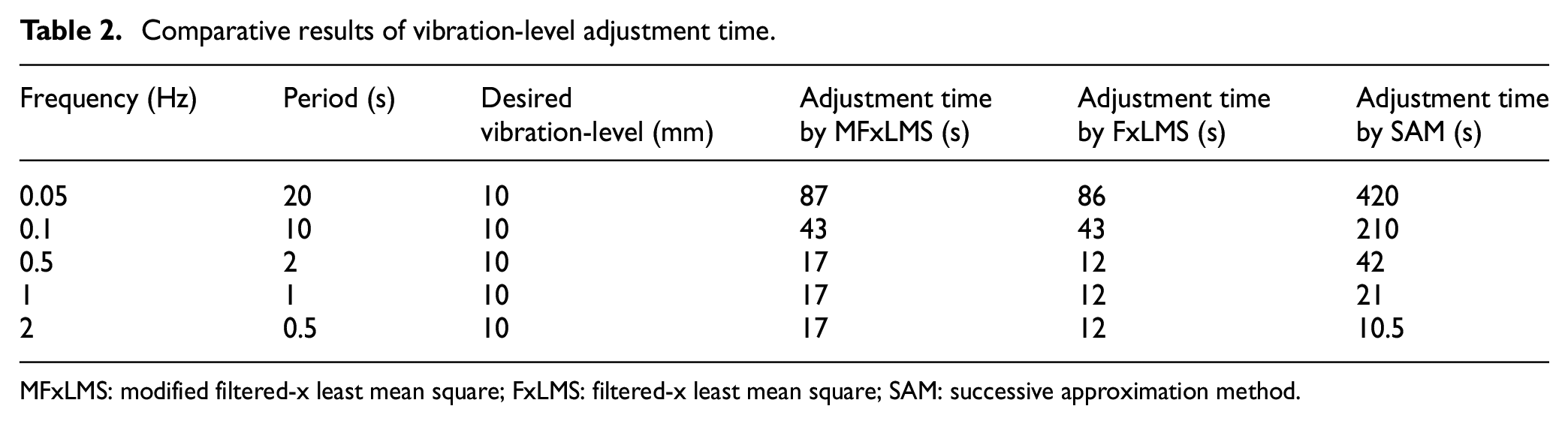
MFxLMS: modified filtered-x least mean square; FxLMS: filtered-x least mean square; SAM: successive approximation method.
In SAM, n is set as 3 in order to obtain a steady measurement. If the error tolerance
where
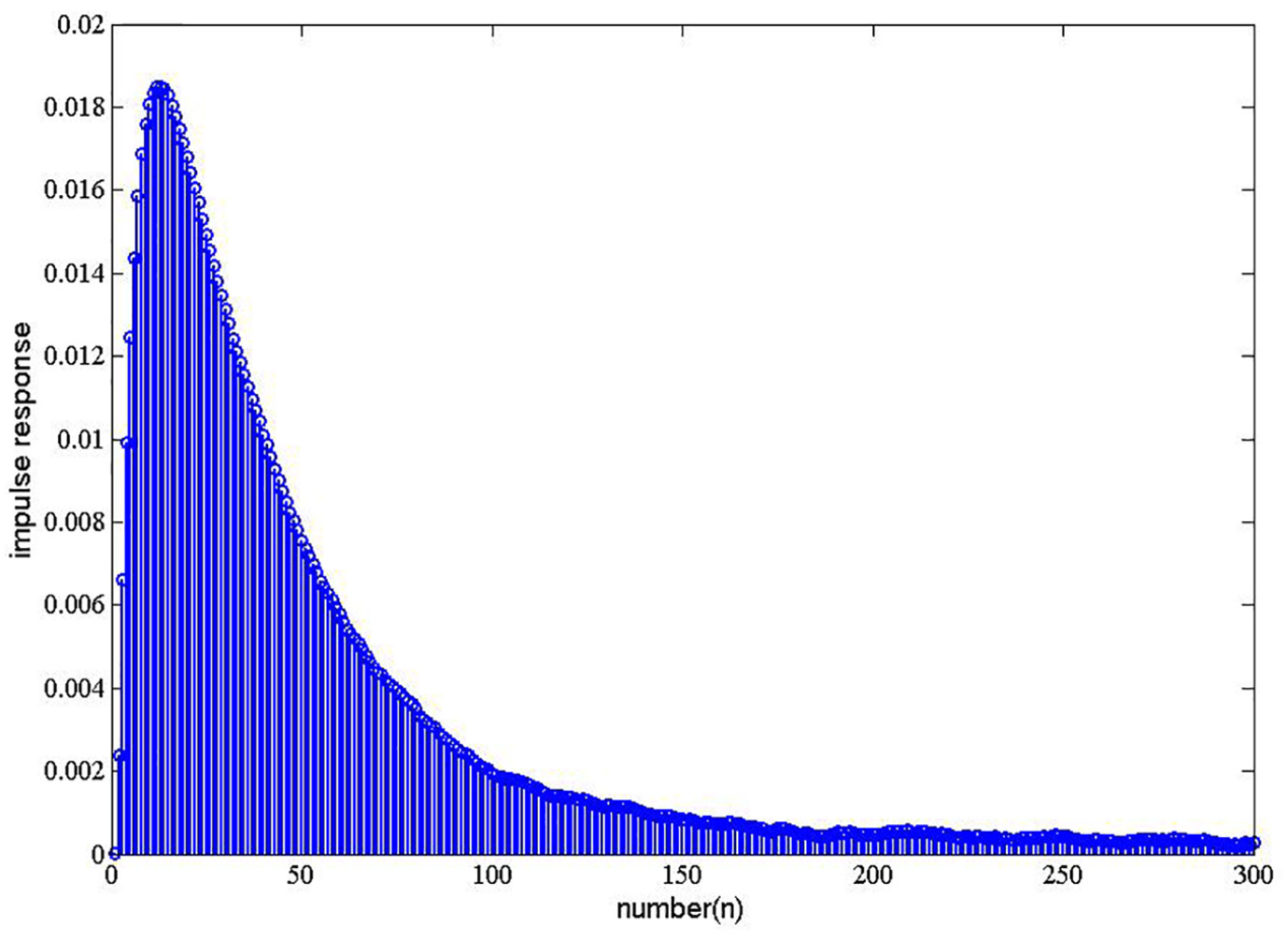
The coefficients of the identified FIR filter for the modeling of the controlled system.
The calculated results of
Comparative results of parameter estimation between FxLMS and MFxLMS algorithms.
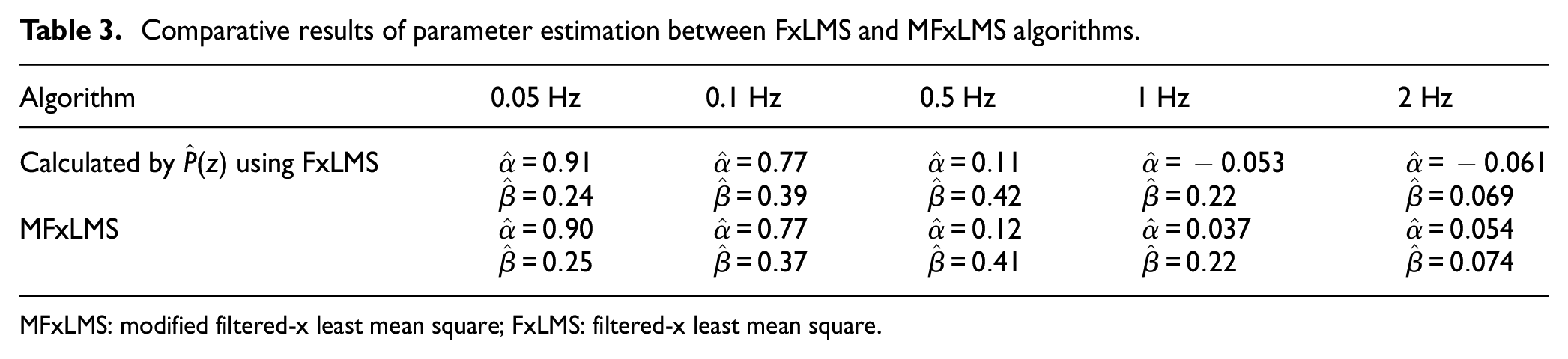
MFxLMS: modified filtered-x least mean square; FxLMS: filtered-x least mean square.
Comparative convergence process of the tracking error for 0.5 Hz is presented in Figure 11 using FxLMS, MFxLMS and MFxLMS2 algorithms. In the MFxLMS2 algorithm, the only difference from the MFxLMS algorithm is that equations (19)–(23) are not included. The values of parameters
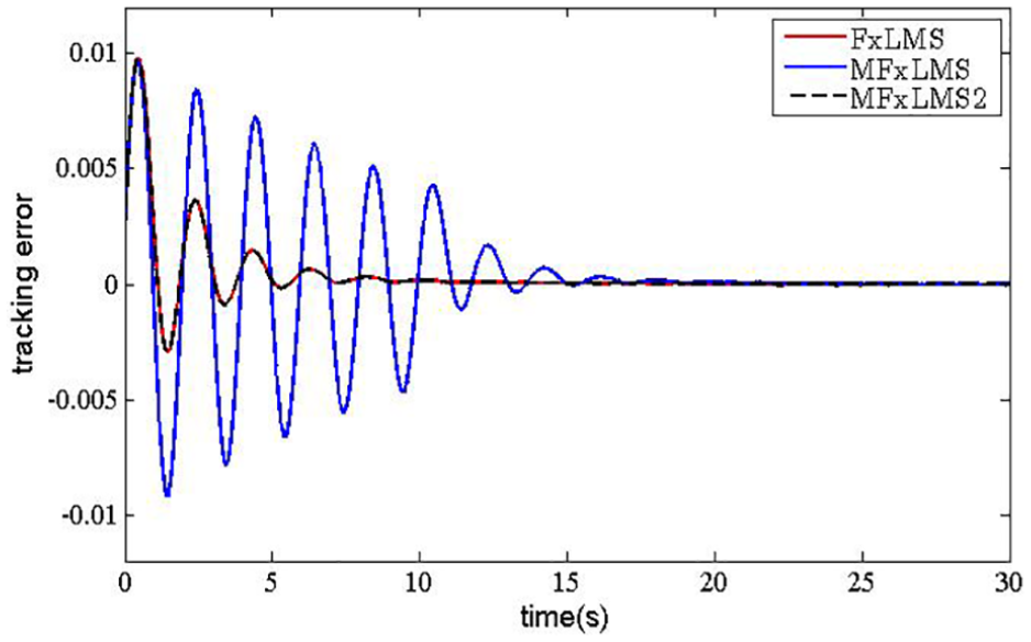
Tracking error convergence of FxLMS, MFxLMS and MFxLMS2 algorithms at a frequency of 0.5 Hz.
To show the improvement in the proposed MFxLMS algorithm more clearly, an overall comparison with FxLMS in the experiments is listed in Table 4. It can be concluded from Table 4 that the apparent advantage of the proposed MFxLMS algorithm over FxLMS is the dramatically reduced computational complexity. Another improvement is that offline identification is not required in MFxLMS. Although the MFxLMS algorithm seems to have slower convergence than FxLMS, fast convergence like FxLMS can be achieved if a prior identification is provided.
Overall comparative results between FxLMS and MFxLMS algorithms.
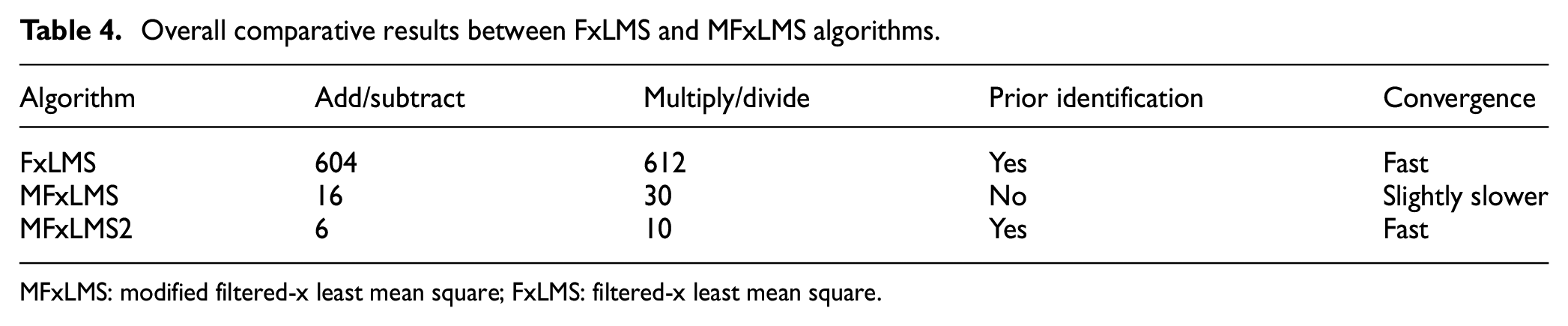
MFxLMS: modified filtered-x least mean square; FxLMS: filtered-x least mean square.
The MFxLMS algorithm proposed in this paper is based on linear assumption of the controlled system. Although excellent tracking performances (maximum error of approximately 0.5%) have been carried out in all the experiments, the nonlinearities of the vibration calibration system should be considered if one wants to further improve the tracking accuracy. The nonlinearities lead to harmonic distortion in vibration calibration system. Instead of nonlinear adaptive algorithms, the harmonic distortion can be more efficiently canceled by the multi-frequency narrowband FxLMS algorithm. However, it increases the computation burden significantly. The MFxLMS algorithm with low computational complexity extending for harmonic reduction will be a topic of our future research.
Conclusion
This paper proposes a novel adaptive vibration-level adjustment algorithm for low-frequency calibration system based on MFxLMS. The MFxLMS algorithm is free of pre-identification and reduces computational complexity significantly compared with the FxLMS algorithm. Convergence analysis of the MFxLMS algorithm is presented in mean sense and the upper stability bound of step size is derived. Experimental results based on a low-frequency calibration system show that the proposed MFxLMS algorithm has excellent tracking performances and requires much less adjustment time in low-frequency band compared with the traditional SAM. The proposed algorithm can be also extended for harmonic reduction, which will be a topic in our further exploration.
Footnotes
Acknowledgements
The authors acknowledge Econ Technologies Co., Ltd. for providing the experimental instruments.
Declaration of conflicting interests
The author(s) declared no potential conflicts of interest with respect to the research, authorship and/or publication of this article.
Funding
The author(s) received no financial support for the research, authorship and/or publication of this article.