
Abstract
Blade tip clearance is one of the important parameters affecting the performance, safety and stability of a gas turbine engine. However, it is difficult to measure the tip clearance in real time and accurately during the development and test process of an engine. In order to promote the development of tip clearance–measuring technology and the optimal design of the gas turbine engine, some typical measuring methods of tip clearance and a novel measuring method based on AC discharge are introduced. In this article, the significance for measuring tip clearance of an engine is illustrated first. Then, operating principles, characteristics and developments of those typical measurement approaches are introduced. After that, these methods are analyzed, and the particular characteristic of each measuring approach is summarized.
Keywords
Introduction
Recently, new types of aircrafts have put forward higher performance and stability requirements for an engine, which has brought great challenges to the development of engines. As an important parameter that affects the efficiency, stability and safety of the gas turbine engine, blade tip clearance, which is the radial distance between a rotor blade tip and the engine casing, has become the focus of researchers. A schematic diagram of the blade–casing clearance is presented in Figure 1. With the rapid development of aero-engine research, the significance of tip clearance on the engine has been shown by the results of a large number of experiments.
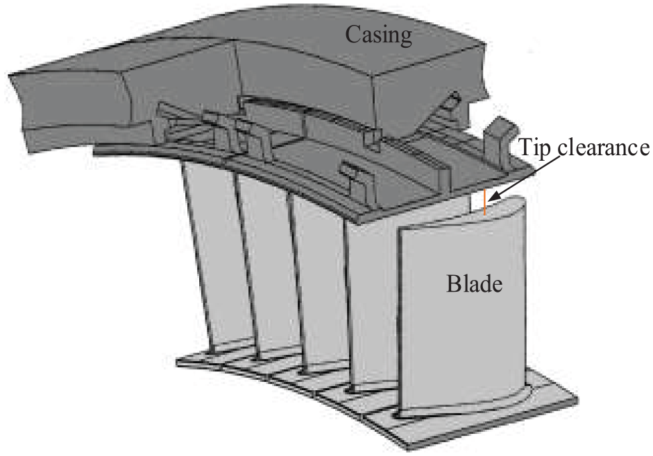
The schematic diagram of blade–casing clearance.
For example, researchers have found that an increase in tip clearance directly results in a decrease in turbine efficiency. 1 That is because as a rotating component, the power that a turbine/compressor can provide/consume depends on the airflow flow through the area where the blade is located. But the presence of the tip clearance causes a portion for the airflow to flow away without work and will damage the flow path, thereby, affecting the efficiency the turbine. With further studies, researchers explored the relationship between the tip clearance and the engine efficiency through experiments. Here, some representative results are listed. And it should be noticed that when all the results are obtained under different experimental conditions, the quantitative indicators are not applicable to all engines, but they all reflect a trend that the larger the tip the lower the efficiency. Researchers found that when the tip clearance is doubled, the efficiency of a low-speed compressor decreases by 1.5%. 2 And when the blade tip clearance of a modern gas turbine compressor increases by 0.125 mm, the efficiency reduces by 0.5%. 3 In addition, the experiments carried out by Australian researchers showed that when the tip clearance of the first stage increases by about 10% of the blade’s length, and due to most of the energy is transferred through the first turbine stage, the output power will reduce by about 11%, dynamic pressure ratio will decline by 4.4%, and static pressure ratio will decrease by 8.46%. Meanwhile, a slight surge of blades will occur, which will affect the engine’s stability. 4 A simulation result showed that compared with configuration 1, which has a small tip clearance of multistage high-pressure compressor, configuration 2, which has a large tip clearance of multistage high-pressure compressor, causes the stable operating range to be reduced by 40%, and the efficiency and pressure ratio are also decreased by 1.5% and 2%, respectively. 5
In addition, the blade tip-clearance changes have a great impact on the rate of fuel consumption. Studies made by the researchers of the British RR company on the modern gas turbine engine showed that with the length of the blade tip clearance increasing by 1%, the efficiency of engine is reduced by about 1.5% and the fuel consumption rate increases by about 3%. 6 And with further researches, a relationship was discovered by researchers that the decrease of the tip clearance reduces the fuel consumption of the engine at a given working point, as well as the working temperature. 7
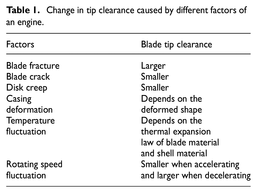
Furthermore, if the tip clearance is too big, it will not only decrease the efficiency of the engine but also consume more fuel and even cause a surge. 8 On the contrary, the decrease in tip clearance can reduce the working medium leakage and the loss of the end wall, so as to improve the engine performance. 9 However, since the tip clearance is small10–12 and the gas turbine engine is working in environments of high temperature, high pressure and large vibration, 13 the factors that cause the changes in tip clearance during the flight are complicated. Among them, temperature and rotating speed are the main factors. In addition, the friction between the fouling caused by corrosion and foreign objects, the change of the operating load of the turbine and the friction between the tip and the sealing strip caused by transition state of the gas turbine will also lead to the changes in the tip clearance. In order to make a clear introduction of the factors that affect the tip clearance, Table 1 is used to sum up some of those factors.
Change in tip clearance caused by different factors of an engine.
Based on the aforementioned factors, tip clearance is hard to be accurately estimated just by theoretical simulation; some simulation results of the blade tip clearance are obtained under simplified conditions, and the accuracy is relatively insufficient.14,15 So far, only the change situation of the tip clearance can be obtained by real-time measurements. Therefore, in order to improve the engine performance and ensure flight safety, it is crucial to research and improve the advanced tip-clearance measurement methods. In the following part of this paper, several representative tip-clearance measurement methods were introduced and compared.
Blade tip-clearance measurement methods
From 1930s, more and more institutes began to dedicate to the researches on blade tip-clearance measurement of the gas turbine engine, the research results obtained by measuring the tip clearance are widely applied in the development of the engine, and some of the institutes have implemented the active tip-clearance control. At present, many researchers and relevant institutes have developed several tip clearance–measuring methods of the gas turbine engine, which mainly include tip-timing method, inductive method, eddy current method, capacitive method, microwave method, optical fiber method, probe method and so on. In the following paragraphs, detailed introduction and analysis of each theory are presented. And the narrative structure adopted in this paper is that, first, the principle of each method is introduced, followed by the characteristics, and, finally, the development history of each method is presented.
Tip-timing method
Specific introduction
As a method of non-destructive testing and evaluation, tip-timing method has many advantages. This method is developed on the basis of pulse modulation method and is the research hot spot of blade vibration–detection direction. 16 In addition, as a measurement method, it can be combined with many non-contact probe technologies. In order to explain its main principles, the tip-timing method, with optical probes, is chosen to be the example and is being introduced here. This method uses two timing sensors to launch two beams of self-collimated light, and the sensors receive the signals when the blade passes through the measurement area. Meanwhile, a rotor speed synchronization sensor is used to monitor rotor speed in real time. With the measured information, the value of tip clearance can be obtained. The specific system diagram is shown in Figure 2. The system includes two timing sensors: a rotor speed synchronization sensor and a signal recorder and monitor. When the experimental data are being collected by the signal-processing module, mean and standard deviation of the measured values of blade tip clearance can be obtained by a computer.
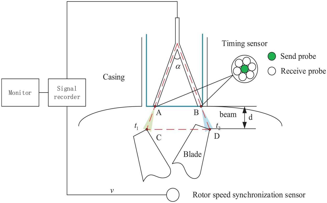
The diagram of tip clearance–measuring system based on tip-timing method.
With this method, there exists an equation 17 as follows
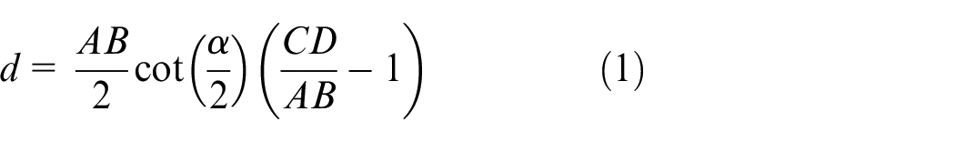
where
With this method, two timing sensors that have a certain angle between each other are being used as a single sensor that can reduce the size of the system, thereby reducing the impact of the measuring system on the rotating machine. The signals collected by the high-speed acquisition model can be considered as digital signals; therefore, the measurement system has a strong anti-interference ability, which means the system can overcome the influence of different scattering characteristics, the influence of the different rotor speed and so on. In addition, this measurement method has no limit on the rotational speed, and it can cover the full range from low speed to high speed in theory with high measurement accuracy. Although this method has lots of advantages, it still does not overcome the disadvantages brought by the probes, such as the optical probes used in the example method, which are easily affected by contamination and are expensive than other probes, and because of the increase in the number of the sensors, the reliability of the system will decrease.
Development history
As a theoretical approach, tip-timing method is always combined with the other measurement methods. With the consideration to keep the complete structure of this paper, the specific development of tip-timing method is divided into different parts.
Inductive method
Specific introduction
The principle of inductive method is to measure the tip clearance by measuring the inductance change in planar spiral coils. 16 There exists a law that the smaller the tip the higher the inductance drops. 18 According to the principle of electromagnetic induction, when a metal passes the magnetic field, an eddy current will occur. This will increase the induction current flow, so the load of the oscillation circuit increases. The sensor can measure the changes, and with the numerical relationship, the tip clearance can be calculated. Schematics of an inductive sensor for tip-clearance measurement are shown in Figure 3. In this system, the rotating blade with magnetic property can generate a high-frequency magnetic. So the sensor can work in the way discussed previously. When the system is working, the coil is electrically connected in parallel with an external capacitor to form a parallel inductor–capacitor (LC) resonant circuit that has a unique resonant frequency. With the purpose of introducing the system completely, a typical data-processing method is discussed here. 18 A digitizer is used to measure and record the data at a 100-MHz sampling rate. Next, the fast Fourier transform (FFT) was conducted to the data to find out the peak values. Then three layers of one-dimensional (1D) stationary wavelet transform (SWT) was performed to improve the signal-to-noise ratio of the peak value signals. Finally, the processed signal can be used by the program to calculate the tip clearance.
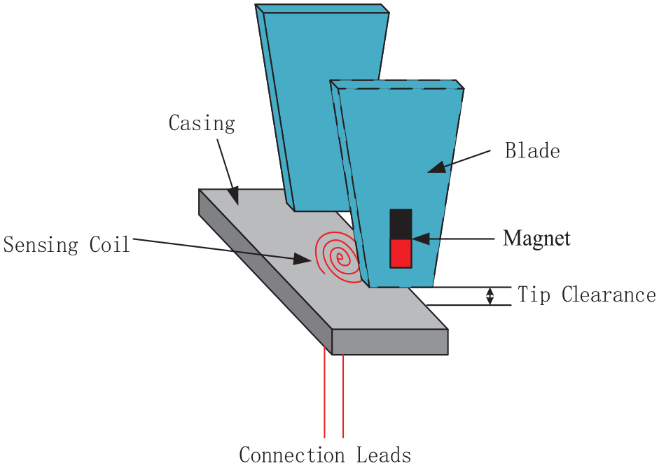
Schematics of an inductive sensor for tip-clearance measurement.
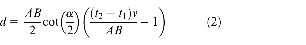
According to Faraday’s law, an equation can be given as follows
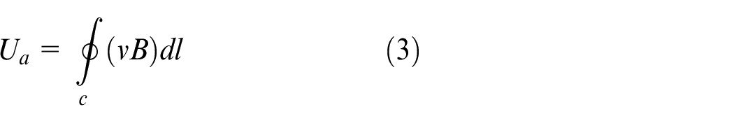
where
The system designed by this method has the advantages of long life, simple construction, high reliability, pollution resistance, low cost and easy installation. In addition, it does not need a through hole penetrating the casing, which is a big advantage. However, when it has so many advantages listed, its disadvantages limit its applications, for example, because of high temperature the magnetic force of the permanent magnet will become weak. Without any additional measures, these sensors cannot operate at high temperatures. The usual temperature is below 400 K, and the sensors may not be useful if the casings are made of ferrous material because a ferrous casing significantly reduces the penetrating magnetic field, and inturn the output signal. 19 In addition, there is another main disadvantage, that is, the sensor needs precise calibration effort, which means the sensors can only detect one tip clearance at a specific location at the blade tip. Based on the aforementioned advantages and disadvantages, a conclusion can be drawn out that in low-temperature environment, such as the compressor stages, they have broad application prospects. When it comes to the high-temperature environment, such as the turbine stages, though some researches had been done,20,21 some works still needs to be carried out.
Development history
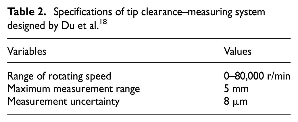
As a method of non-contact measurement, the inductive sensor, known as speed pickup or variable reluctance (VR) sensor has been used for blade tip timing in compressors and steam turbines since the late 1940s. 20 This method does not require a through hole, and it arouses a great interest among researchers. A non-intrusive inductive tip-clearance sensor, made up of a three-dimensional (3D) solenoid wound around a magnetic core, has been developed. 19 With the purpose of minimizing the effects of external electromagnetic interference caused by the input impedance approaching 0, a new sensor was designed by researchers, which uses a low-impedance coil with a limited number of turns. The current flowing in the coil circuit can describe the motion of the blade tip. 22 In 2015, researchers have developed a high-sensitivity inductive sensor for measuring clearance of a rotating blade tip, which includes one or more sensing coils. It can identify the distance between the coil and the tip of the rotating blade, which can be obtained using predetermined calibration curve values. 23 In order to overcome the disadvantage that the installed sensor can only detect one tip clearance at a specific location, multiple sensing coils are used by researchers. With this step, the tip-clearance sensor can simultaneously detect the blade tip clearances at various positions. 18 A dynamic experiment using a bench-top test rig demonstrated that the sensor is capable of measuring tip clearances ranging from 0 to 5 mm with a resolution of 10 μm. The system specifications are shown in Table 2. As for the limitation of the operating temperature, researchers have tried a lot to overcome it. For example, using the bypass air to cool the sensors, the system can be operated in an environment with a gas temperature of 1373 K. 20 Researchers have found that using ceramic materials to insulate the sensing coil can protect the coil from being oxidized at high-temperature environments effectively. With this measure, the operating temperature can be increased to 1300 K, while the sensor still has a high accuracy. 21 But it should be noticed that the measurement signal of an inductive sensor is inevitably affected by temperature variations due to its working principle and unavoidable temperature drift problems, though there are some researchers working on this problem. For example, using temperature-compensation circuit to eliminate temperature drift of inductive sensor from 293 to 773 K was proposed by Lv and Zhu. 24 This problem still needs more reasonable solutions.
Specifications of tip clearance–measuring system designed by Du et al. 18
Eddy current method
Specific introduction
American, British and Russian researchers are devoted to developing eddy current method, which is a common method for measuring tip clearance today. As a branch of inductive method, this method applies a magnetic field variation produced when metal passes the magnetic field lines to measure tip clearance, and the measurement device mainly consists of a probe, a detector, an oscillator, which is composed of detection circuit, and so on. First, the coil is placed on the engine casing at a certain distance. When the alternating current is turned on, the coil generates a magnetic flux, and the metal blade is induced by the magnetic beam to generate a ring current. This current produces a reverse magnetic flux on the coil that ultimately changes the reactance of the coil. This amount of change is detected by the bridge circuit, amplified, rectified and put it out. With this principle, measurement of tip clearance can be achieved. The principle diagram of eddy current method is shown in Figure 4.
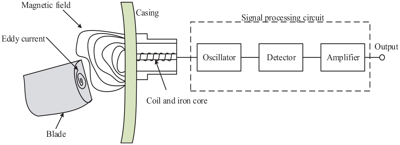
The principle diagram of eddy current method.
The equivalent impedance of the coil can be expressed as follows

where
With the purpose of explaining the relationship between Z and
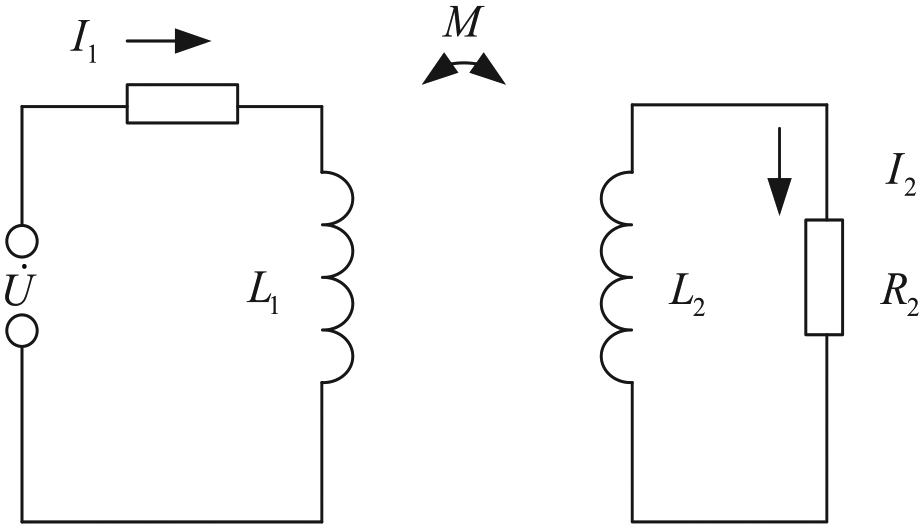
The simplified equivalent circuit of eddy current method.
With the Figure 5, the following equation 25 is obtained

where
With equation (5), the equivalent impedance can be calculated as follows
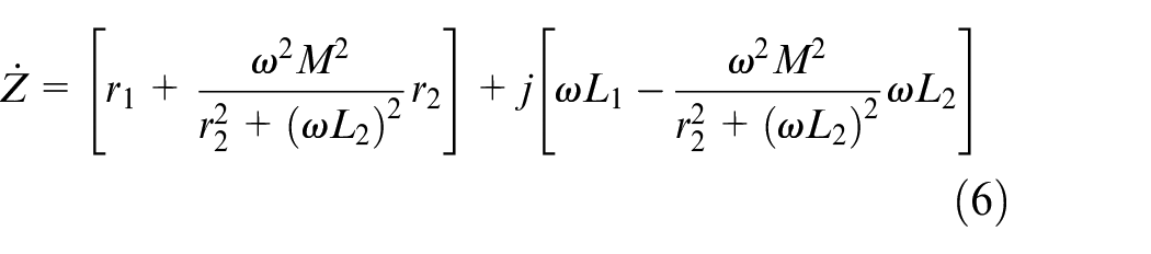
So the equivalent impedance of the sensors is related to the distance between coil and measured conductor, which can be the basis of eddy current inductance measurement.
In other words, the main idea is that, by keeping the other parameters unchanged except the distance between the coil and the measured conductor, the equivalent impedance of coil is only affected by the value of
With Figure 4, an eddy current sensor placed outside of the casing is introduced, which can be named with “no hole” scheme because it does not need a through hole on the casing. But it should be noticed here that it is not the only scheme of this method. This is because though this method is a non-contact measurement that can measure the tip clearance while maintaining the casing integrity so as to attenuate the impact of the measurement system on the engine, its working principle requires the casing material do not drastically change the magnetic field lines of the sensor. That means the sensors are not suitable for the case where the casing are made of ferrous shielding materials. So with the purpose to expand its using scope, researcher will choose to open a through hole on the casing sometimes, and in this way, the sensor is being placed in the inner surface of the casing, this scheme can be named with “with hole” scheme. Although this scheme destroys the integrity of the engine casing, it avoids some disadvantages of “no hole” scheme. For example, unlike the “no hole” scheme, the sensors using “with hole” scheme are more insensitive to relative vibration between the case and the sensor and the weakening effect of the casing on the signal is eliminated. In practical applications, researchers will make a flexible choice according to specific requirements.
In order to distinguish the difference between the two schemes, in the following development history section, “no hole” and “with hole” will be used.
The method has advantages of simple structure, small size, light weight, high sensitivity, wide measurement range, strong anti-interference ability and without complex adjustments. However, this method is affected by the blade material and with a small bandwidth that is usually between 10 and 100 KHz. In order to produce a sufficiently obvious signal, the blade tip is required to have a certain thickness that is generally required to be greater than 5 mm for an industrial eddy current sensor under 100 KHz. As the sensor output is related to the shape of the tip, installation state and temperature, it is necessary to be calibrated in advance to make it suitable for the application environment. The output of the sensors may be affected by the environment factors. The relationship between the input and the output will be nonlinear, which challenges the processing of the signal. In order to reduce the effect, a typical way is to add a nonlinear correction module in the system so that the signal received by the sensor can be compensated. Researchers usually use least squares method to fit the curve 26 so that the linear relationship between the input displacement and the output voltage can be achieved.
Development history
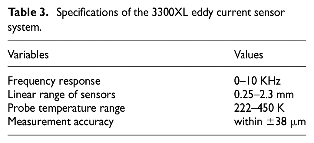
The eddy current method for distance measurement was first proposed by researchers in 1977, the method validity was confirmed by experiments. 27 Soon, this approach was utilized to measure blade tip clearance; Sutcliffe made a great contribution to the application of the method in tip-clearance measurement. Researchers of Hood Technology Corporation designed an eddy current sensor made of a magnet and an iron return path wrapped with a coil. Researchers found that with a shielding material in front of the sensing face, the signal was not adversely affected. Based on this phenomenon, they studied the “no hold” scheme. The sensor they developed could withstand the operating temperature above 810.9 K and do not need to penetrate the engine casing. The heat resistance of the sensor has been increased obviously, which made its applications wider. 19 However, it still does not meet the requirements for the tip clearance measurement of high temperature components. With the purpose of improving the heat resistance of sensor, an eddy current sensor for tip-clearance measurement was designed by researchers, which could work at a high temperature of 1075 K. The sensor had been employed for active tip-clearance control and made good results.28,29 These sensors belong to the “with hole” scheme. In 2008, a tip-timing sensor using eddy current sensors was developed for the measurement of rotor blade and engine testing. 30 After that, new sensors are constantly evolving. For example, researchers developed a sensor with coil wound on a rectangular former, and this can improve the resolution of the device when used for sensing the passage of objects of elongate section. 31 An eddy current sensor based on a pulse-trigger technology was developed in 2016, which improved the accuracy of eddy current probes in the insufficient sampling condition caused by the limit of narrow-band, and the system accuracy could reach 0.06 mm; 32 this method is of “with hole” scheme. An eddy current sensor based on piezo-cantilever sensing principle for both blade-timing and tip-clearance measurements was designed; the system had the advantages of non-contact, low power consumption, insensitivity to contaminants, the validity of the system had also been demonstrated by tests for the purpose of further application. 33 Currently, due to its small size, small weight and high precision, the eddy current method has been widely used. 34 There are some mature products of eddy current displacement sensors on the market, and they are widely used around the world due to its stability and reliability, for example, the 3300XL eddy current sensor system produced by Bentley, USA. The specific system parameters are shown in Table 3. With the continuous efforts of the researchers, some sensors that can perform at extreme environments without losing accuracy are being developed.29,35 The eddy current method is verified in a laboratory with 3000 r/min revolution and 1300 K temperature. 21 They all belong to the “with hole” scheme.
Specifications of the 3300XL eddy current sensor system.
Capacitive method
Specific introduction
As one of the most effective methods for measuring tip the working principle of capacitive method is to measure tip clearance by acquiring the variable capacitance formed between sensors probe and blade tip. The blade tip-clearance changes would lead to the changes of capacitive, and then the change values are being converted into voltage/current signal, so that the change value can be easily detected and analyzed through the detection circuit and processing circuit. Therefore, tip clearance can be obtained by measuring the output electrical signal. The system diagram of a capacitive method is presented in Figure 6.
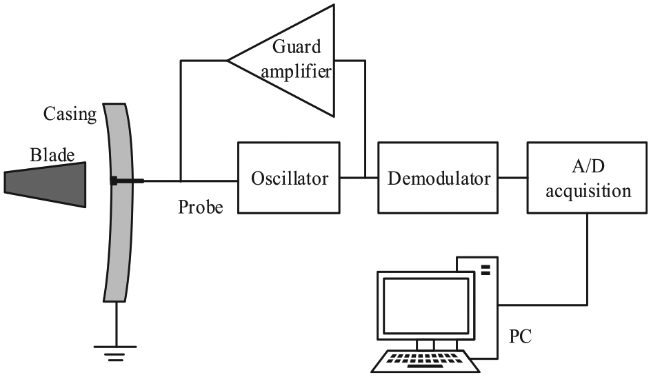
The system diagram of a capacitive method.
As a variable parameter, the capacitive value can be calculated by the following equation 16
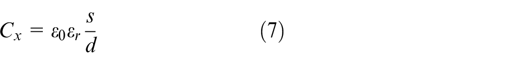
where
When the measurement device is working, apart from the changing tip clearance, other parameters remain unchanged. So according to the equation (7), the measured capacitive value
As a non-electricity measurement method, in order to establish the relationship between the measured non-electricity values and the sensor output, the characteristic curve of the sensor should be obtained first. And the usual ways to get the curve are lookup table method, least squares method, Lagrange polynomial interpolation method and cubic spline interpolation method. With the requirements of precision and real time, the typical way researchers choose to use in the measurement of tip clearance is Lagrange polynomial interpolation method. 36
The advantages of the system include the following aspects. First, the measurement system structure is simple, and each blade tip clearance can be obtained no matter the blade thickness changes or not. Second, capacitive sensors have the advantages of high sensitivity, high natural frequency, wide band, small power, high impedance, good dynamic response performance, and it can work under high frequency. Third, both the tip clearance and blade vibration can be measured and detected simultaneously by this method. However, the system needs to be accurately calibrated and installed, which limits its application. In addition, the system accuracy is easily affected by many factors such as the change of medium dielectric constant, environmental disturbances (magnetic field and electric spark), probe and casing thermal deformation and calibration error. Meanwhile, when the material performance is not good, the insulation resistance will change with the temperature and humidity, which can lead to the zero drift of the sensor.
Development history
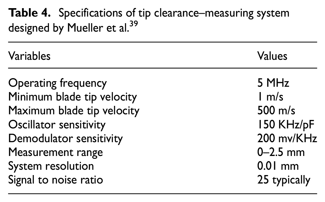
Measurement scheme based on capacitive frequency modulation was first proposed by researchers in 1987, and it was applied to measure tip clearance in testing machine, the experiments’ results verified the feasibility of the scheme.3,37 The reason why the frequency-modulated (FM) system rather than the DC (direct current) capacitance probe system is chosen is that the FM system can eliminate the DC error, which is the major influencing factor of measuring accuracy. Researchers applied two types of inputs (ramp and DC) and a dual-amplifier circuit for measuring the blade tip clearance in the turbine engines; by this way, the measurement system can tolerate variations of the probe and cable parameters induced by the environment.38,39 As high-frequency carrier was not employed in the system, the system’s structure was more simple and economical. A sensor system based on capacitive method that used the probe made by glazed alumina material was developed by researchers. 40 The special material used in this system improved the system’s heat resistance, which caused the system could work in the harsh environment of the turbine. Its measurement accuracy reached 15 μm. In order to measure the tip clearance in the compressor and turbine of a BR700 gas turbine, people developed a system based on frequency modulation capacitive probe, its resolution can reach 10 μm; the system specifications are shown in Table 4. 39 In 2005, researchers look at the potential for a dual-use capacitance probe sensor to measure both tip timing and tip clearance. The system designed by them has the ability to detect blade vibration across resonance. 41 A capacitive method sensor-based ratio-metric measurement principle with synchronous detector was developed to measure the tip clearance of a microturbine; the system accuracy is about 0.8 μm in the range of 100 μm. 42 Then the research group developed a simple active tip-clearance control system based on a synchronous detection technology of a phase-modulated signal in the micro gas turbine, which made the applications of the sensor more extensive. 43 In their research, periodic autocalibration was used to reduce the effects of temperature drift on the sensor output. The main idea is to match the parasitic board capacitances arranged in parallel with the reference and the probe capacitors carefully. In order to remove the influence of the distributed capacitance introduced into the system by the cable, researchers proposed two different methods: one is to ground both plates of the capacitor, but it is unsuitable for the measurement of tip clearance while the blades are as one plate of the capacitor. The other one is to make the potential of the cable’s inner shield to track the potential of the sensor capacitor plate point to point. 44 In recent years, researchers studied different configurations for capacitive gauges and found that wide bandwidth is required for accurate measurement of the turbine engines’ tip clearance. According to their experimental results, as the bandwidth of the gage is reduced, the pulse amplitude is reduced and the pulse is delayed, which will lead to the increase of the measurement error of the tip clearance and the error of the blade’s apparent position. So with the purpose of accurate measurement, a bigger bandwidth is the direction of technological development. 45 Nowadays, because of its high heat resistance, small size and light weight, the capacitive method has been one of the most effective methods for measuring tip clearance, and it is used worldwide. Many companies have developed the capacitive displacement-measurement systems. For example, Micro-Epsilon’s CS series capacitive displacement-measurement sensors have good precision; the AS-5000 sensor developed by Milliren Technologies, Inc., America. (MTI) has a high precision, which can reach 0.0025 μm.
Specifications of tip clearance–measuring system designed by Mueller et al. 39
Microwave method
Microwave method can be divided into two different methods according to the working principle. One is the microwave method based on phase ranging, while the other is the microwave method based on resonant frequency. Between them, the microwave method based on phase ranging is the mature and traditional working principle, and both are very promising measurement methods.
Microwave method based on phase ranging
Specific introduction
Microwave tip clearance–measuring system based on phase ranging includes four main parts: microwave generator, signal-adjusting circuit, phase detector and microwave probe. The working principle of the system is that the sensor emits a continuous microwave signal, and when the signal reaches the blade tip, it will reflect. The phase of the microwave signal reflected by the tip will be different than the internal reference signal. Thus with the change value of the phase, the value of the tip clearance can be obtained. The system diagram of a microwave method based on phase ranging is presented in Figure 7.
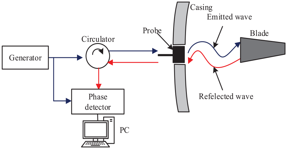
The system diagram of a microwave method based on phase ranging.
With this method, there exists the following equation 46

where
Due to the effect of spatial filtering effect, signal leakage and so on, the precision of the sensor will decrease. So the measure signal should be corrected. The typical way to get the correction coefficients is to put two test signals with stable frequency difference into the mixer and use the spectrum analyzer to analyze the output intermediate-frequency signal. 47
The advantages of this method include that, first, the sensor has the internal self-calibration function, which means that the sensor can work properly regardless of the temperature and wear of the rotating blades. Second, the sensors are not affected by vibration and length of the cable. But, as the radiation spot of the microwave system is relatively large, there must be an inevitable spatial filter in the measurement system, which will limit the accuracy of the system. When the tip clearance is lower than 2 mm, the measurement is less sensitive due to the near-field effect of the microwave sensors. 48
Development history
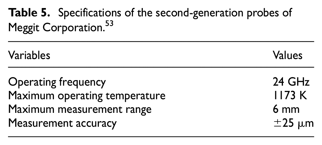
The first application of this method on a 65-MW gas turbine was reported in 1998. 49 Further researches ware made in the following years, researchers designed a microwave tip-clearance measurement system that could operate at a high temperature of 1900 K, and the measurement accuracy of the system reached 0.05 mm. The experimental results confirmed the possibility of the microwave system to be simultaneously applied to measure the tip clearance, rotor axial displacement and blades extension.50,51 In 2013, an optical-electromagnetic model based on microwave blade tip sensor was developed; this model could make precise phase measurement for relatively small blades, and it could calculate and analyze remotely without practical tests that are expensive and time-consuming, which greatly saved time and labor. 52 A new 24-GHz microwave sensor system for real-time tip-clearance monitoring of small-size turbines was developed by researchers; the system was verified by software simulations and prototype experiments. 53 The measurement results were similar to the simulation results, and the system was finally used in an actual engine. The measurement accuracy of the system reached 25 μm. They used the second-generation probes of Meggit Corporation in the experiments, whose specific system parameters are shown in Table 5. In 2015, a microwave-sensing system based on short-range radar principle was developed by researchers; with the use of microwave method, the system could withstand high-temperature and high-pressure environments. 54 In 2017, researchers designed a microwave sensor–based blade tip-timing measurement system that used a 24-GHz microwave sensor with an outer diameter of 8 mm. With the results that they obtained, the system was considered feasible for use in applications with a polluted medium. 55
Specifications of the second-generation probes of Meggit Corporation. 53
Microwave method based on resonant frequency
Specific introduction
Different from the aforementioned method, the work principle of this method is that the resonant frequency of the microwave resonator would be affected when the blade approaches or leaves the microwave probe, so the tip-clearance value can be obtained by calculating the resonance frequency difference of resonator under different conditions. The main differences of the measure system guided by this method to the measure system guided by microwave method based on phase ranging are the structure of the sensor and the types of detector. The system guided by this method needs probes with resonator and a detector to monitor the resonant frequency rather than the phase. The phase detector should be replaced by a frequency detector. Except that, the remaining parts are the same as Figure 7. With the purpose of distinguishing them, the probe diagram with a resonator is presented in Figure 8.
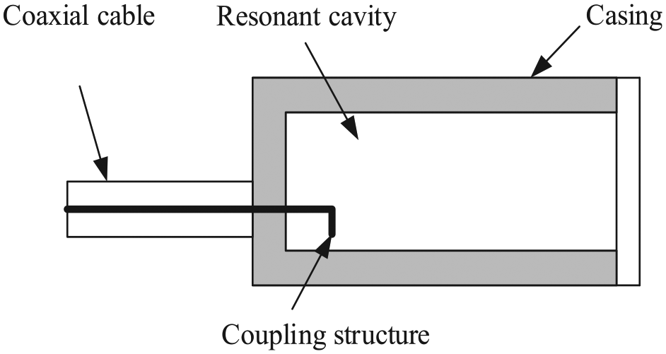
Probe with a resonator.
As the microwave technology is based on the principle of resonance frequency measurement, the impact of fuel and other pollution can be ignored, and sensors can work at temperature of 1173 K. 56 However, this kind of sensor requires extremely high resonant frequency; otherwise, it is difficult to meet measurement demand.
Development history
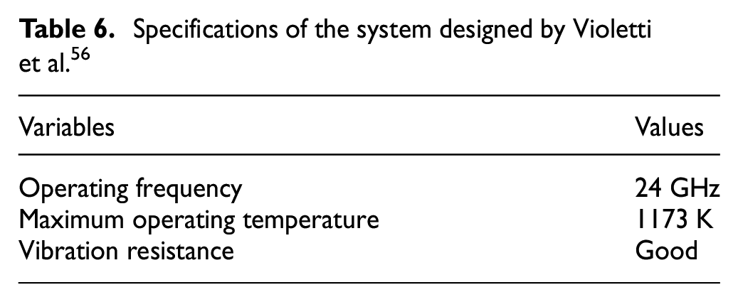
In 1996, researchers in the United Technologies Research Center (UTRC) designed a tip-clearance measurement system with the microwave method based on a resonator structure; the system can be simultaneously used for tip-clearance measurement and active tip-clearance control of gas turbine engine, and results of the experiments were satisfactory. 57 In recent years, researchers developed a novel 24-GHz microwave system for real-time blade tip-clearance monitoring. The system employed high-temperature-resistant circular waveguide resonator probes, and the suitability of the system for real-time blade tip measurement was tested on a DM80 engine; 56 the specific parameters of the system are shown in Table 6. Chinese researchers designed an open resonator structure sensor based on the microwave method. The sensor model operated at 24 GHz, and through the simulation calculation, the measurement range is between 0 and 6 mm. 58 At present, because the sensors using microwave method can work in harsh environments of the engine, it has become a promising method for measuring the tip clearance; however, the high realization costs will be the key problem for researchers to solve.
Specifications of the system designed by Violetti et al. 56
Optical fiber method
The optical fiber method is generally divided into the reflection-type optical fiber method, the optical probe measurement method and the laser Doppler position method. Among them, the laser Doppler position method is a new developing direction of the optical tip clearance–measuring technology. Limited by the working environment, they do not perform well in high-temperature component gap measurement in high-brightness environments.
As for the measures to guarantee the measurement reliability and accuracy, introducing reference fiber compensation, high-precision amplification circuit and filter into the measurement system are the typical ways.
Reflection-type optical fiber method
Specific introduction
The working principle of this method is that when the light emitted by the light source passes through the optical fiber to the blade, the reflected light is received by the receiving optical fiber, and then the photosensitive device receives the light output from receiving optical fiber. The output light intensity depends on the distance between the reflector and optical fiber probe, so that tip clearance can be obtained by detecting light intensity. The system diagram of the reflection-type optical fiber method is presented in Figure 9.
The system diagram of the reflection-type optical fiber method.
The system has several advantages of high sensitivity, high resolution, anti-electromagnetic interference, stable performance, design flexibility, the ability to work in harsh environments and the potential to be applied for static and dynamic real-time detection. However, the system structure is complex, and if the blade surface is ablated by high temperature or is contaminated by some factors, the reflection coefficient of the blade will decrease, so the system sensitivity is reduced. Assuming the reflector and the fiber is perpendicular, if the reflector surface is slightly oblique, it will have a great effect on sensitivity. These shortcomings limit its application.
Development history
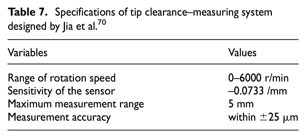
Dhadwal first developed an optical scanning system for experimental engine researches. The system incorporated the technologies of fiber optics and semiconductor laser sources for monitoring blade tip deflections, vibrational modes and changes in blade tip clearances in the compressor stage of rotating turbomachinery. The system resolution can reach 50 μm. 59 In 1998, in order to reduce the light spot and improve system efficiency, researchers added self-collimation optical fiber into the measuring system. They used two sensors to measure the time difference between the blades, so that the tip-timing signal can be used to estimate the tip clearance. 60 By this way, the measuring system was insensitive to most environmental factors, which greatly improves the reliability and measurement accuracy of the system. With further researches, researchers designed an optical fiber sensor based on reflected light-intensity modulation for tip clearance and vibration of the blade, and the experiments were being carried out on Motoren-und Turbinen-Union (MTU). The results showed that the system resolution can reach 15 μm. 61 In 2009, a novel method based on optical low-coherence reflectometry for monitoring the tip clearance was presented by researchers. The measuring probe was robust, inherently self-calibrating and insensitive to environmental variations, and its accuracy is better than 10 μm, which reaches 4 μm. 62 Researchers designed a reflective intensity-modulated optical fiber sensor in 2013, which could simultaneously do tip-timing and tip-clearance measurements. Then they made some improvements to the optical sensor and studied four different configurations of the sensor; the research results were very helpful to develop applications related to structural health monitoring system or active clearance control systems.63–65 Based on past results, they applied the reflected intensity-modulated optical fiber sensor for the health monitoring of engine by measuring real-time tip-timing and tip-clearance measurements, and the tip-clearance measurement for the first stage of an aircraft engine’s compressor was carried out using the optical fiber sensor; its main component was a tetra-furcated bundle of optical fibers, with which the resulting precision of the experimental measurements could reach 12 μm.66–68 Recently, they carried out experimental researches on the vibrational behavior of a rotating disk by three optical fiber sensors, which demonstrated the suitability of this innovative optical system to characterize rotating disks in simulated working environments of the engine. Using this sensor, not only the amplitude and frequency of the vibration but also the number of nodal diameters of the disk and its variations during the tests can be identified. 69 In recent years, the study on this field is still a hot spot. Researchers developed a tip clearance–measuring system composed of the reflective intensity-modulated optical fiber bundle, main signal-processing unit, high-speed data acquisition card and a computer. 70 The good response characteristics of the system could provide a wide prospect for its use in engine-health monitoring or fast-action tip-clearance control; its accuracy could reach 25 μm, and the system specifications are shown in Table 7.
Specifications of tip clearance–measuring system designed by Jia et al. 70
Optical probe measurement method
Specific introduction
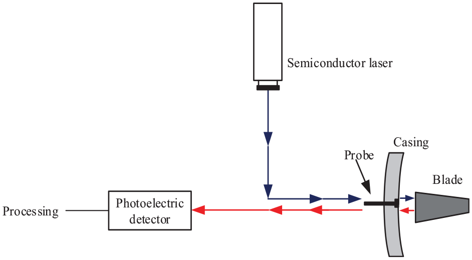
The method principle can be introduced as follows. First, a laser beam emitted from the probe is projected onto the measured object, and then when the gap changes, like from position A to position B, the position of the light spot on the photoelectric receiver changes with different return path of reflected light which is distinguished by virtual line and solid line. Then the clearance can be obtained by calculating the change quantity. The system diagram of the optical probe measurement method is shown in Figure 10. The system includes a laser generator, a probe, an optical fiber, a photoelectric conversion device, a signal recorder and a monitor.
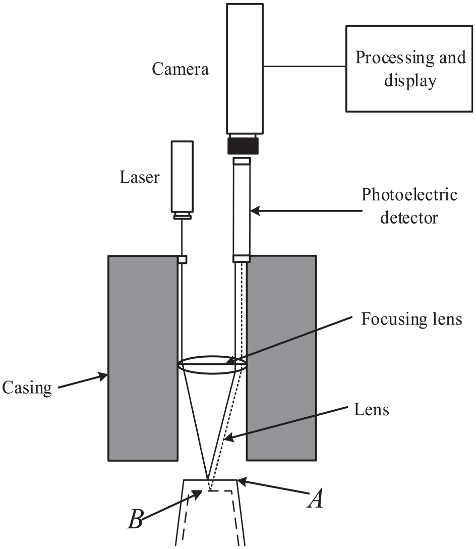
The system diagram of the optical probe measurement method.
The system characteristics include that no limitation to the measured object material, high measurement accuracy, fast frequency response, small fiber probe size and easy to install, it can work in high rotating speed environments and suitable for static and dynamic real-time detection. However, the system is hard to realize, and the working environment is high temperature, high pressure and large vibration; therefore, the system should be protected to avoid pollution and equipment damage.
Development history
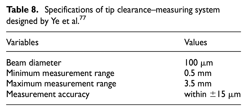
In the middle of 1980s, an optical triangulation technology was developed, which was applied to the gas turbine engine and realized the online measurement. Many researchers had studied this kind of measurement technology, and some research results had already obtained the practical application.71–75 Researcher of Tianjin University designed a multi-mode optical fiber coupled laser ranging system. Multi-mode optical fiber was utilized for optical transmission, which ensured that the system probe could receive enough light power. 76 The resolution of the system is about 0.02 mm under the range of 9 mm. Furthermore, they proposed a rotating blade tip clearance–measuring technique using blade-tip timing and dual-frequency laser phase ranging, 17 and they verified its effectiveness with experiments. Some researchers designed the multi-beam sensors with a triangular cone layout, and they developed a blade tip clearance–detecting technique based on the multi-beam tip timing. After that, they put it into the measurement of blade tip clearance. 77 The system specifications are shown in Table 8. In 2015, researchers designed a distributed fiber-optic sensing system that is unaffected by temperature, and the system can be used on the measurement of gas turbine. 78 In addition, researchers still pay attention to the tip-timing method; they compared different analysis methods for tip-timing data. 79 And after that in 2016, researchers studied the method to improve the blade-tip timing accuracy of the fiber bundle sensor. They used both software and hardware to reduce the errors caused by the tip-clearance change, and the effectiveness of the proposed method was proved by experiments. 80 And the uncertainties of blade-tip timing were also studied by researchers.81,82
Specifications of tip clearance–measuring system designed by Ye et al. 77
Laser Doppler position method
Specific introduction
Using the laser Doppler position method to measure tip clearance is a new developing direction of the optical clearance-measurement technology. First, the frequency of reflected light (or scattered light) is related to the velocity of the blade and the spacing of the interference fringes when the blade passes through an interference fringe area at a certain speed. If the interference fringe spacing along the radial direction of the blade is monotonously increasing (or decreasing), it indicates that the tip clearance and the speed of the blade are changing. Wavelength division multiplexing is used to generate two sectorized interference fringe systems with opposite fringe spacing gradients within the same measurement volume. With this, not only the velocity but also the position of moved objects can be determined. The position of moving objects (e.g. turbine blades) can be determined via the monotonic quotient function of the two measured Doppler frequencies. The structure diagram of the laser Doppler position system is presented in Figure 11.
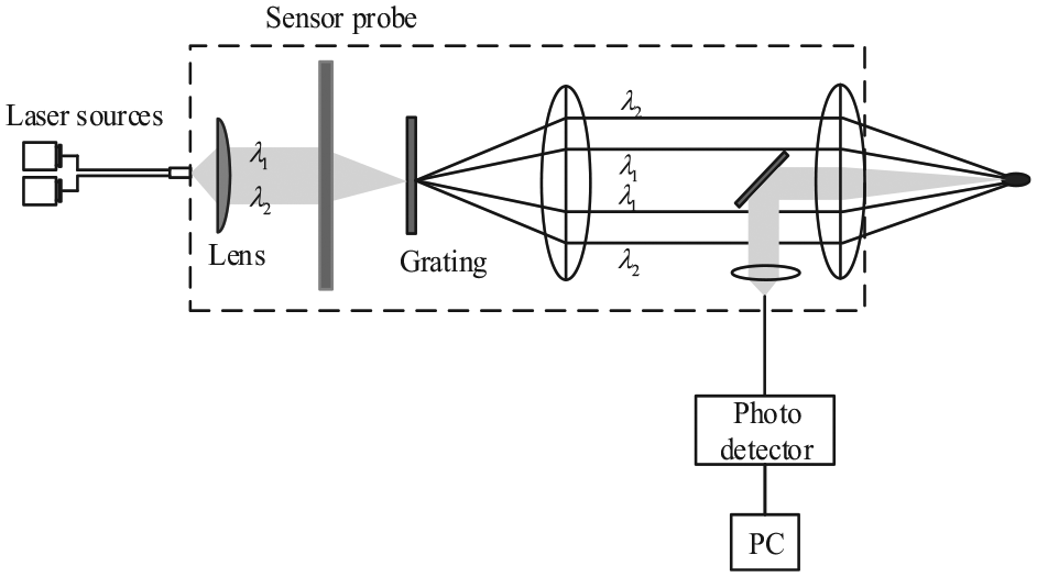
The structure diagram of laser Doppler position system.
The system advantages include high measurement accuracy and insensitive to the blade speed. However, how to miniaturize the probe so that it can be used on the operating engine is still a challenge. In addition, with the aim to operate in real time, the system raises high requirements for signal-processing units.
Development history
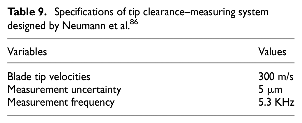
Using the laser Doppler position method by combing laser technology and optical fiber technology to measure single blade clearance and vibration in a turbine engine was first presented in 2006, and the system had high temporal resolution and high position resolution.83,84 Using fiber probes made the system more flexible and not affected by temperature and electromagnetic disturbance. The system’s measurement accuracy is 20 μm. Then researchers applied the technology for vibration monitoring and tip-clearance measurement on a working compressor at speeds of up to 50,000 r/min and 586 m/s blade tip velocity, which was superior to many conventional tip-clearance measurement methods. 85 A new laser Doppler position sensor was introduced in 2015, which could be applied to simultaneously measure the tip clearance, blade vibration and the velocities of the blades; the sensor is insensitive to electromagnetic disturbances and has no limitation to the material of the blades. Its spatial resolution is 5 μm. 86 The system specifications are shown in Table 9. Since the laser Doppler position method can simultaneously measure the tip clearance, blade vibration and the velocities of the blades, the applicable prospect of the method is very extensive.
Specifications of tip clearance–measuring system designed by Neumann et al. 86
Probe method
Specific introduction
Probe method is the tip clearance–measuring method based on spark discharge principle. Its specific working process can be described as follows. First, the probe with DC (direct current) voltage is moved along the radial direction by a stepping motor, and then, when gas discharge occurs between blade tip and probe, the probe stops moving; the tip clearance could be obtained by measuring the moving distance of the probe from the casing. The diagram of tip clearance–measuring system based on probe method is presented in Figure 12. The system mainly consists of a probe, an actuator, a controller and a computer.
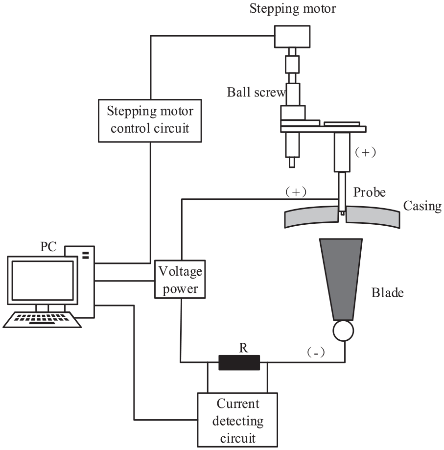
The diagram of tip clearance–measuring system based on probe method.
The characteristics of probe method are that its principle is relatively simple. As long as the blade is a conductive material, no matter how the blade tip shape is, the tip clearance can be measured stably and reliably by probe method under high-temperature and high-pressure environments. However, the original method can only measure the minimum tip clearance of the engine rotor. The fluctuations of applied voltage, temperature and the working fluid’s pressure, and the end face deface of the probe and blade would all change the discharge starting distance, and then to produce measurement deviation. The structure of mechanical actuator applied for probe motion is complex, and manipulation of the device is also required to be skilled. The risk of collision between the probe and the blade limits the maximum operating rotating speed. Meanwhile, the probe is not suitable as a fixed equipment in a shaping engine. It is more suitable for the experimental study, and it can measure the gap between the longest blade and casing under stable state, which also can be a reference for other tip clearance–measuring methods.
Development history
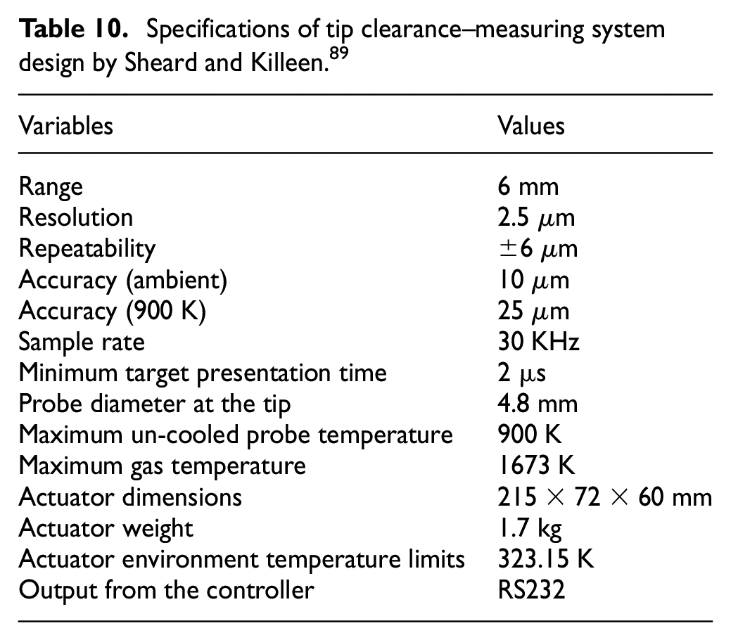
The discharge probe sensor to measure the distance between the blade and the casing was first designed in 1983, and the method was applied successfully for the minimum tip-clearance measurement in the following years. 87 After that, people developed the second-generation tip-clearance measuring system based on discharge probe method, which can only measure the tip clearance of the longest blade, and the system resolution was 2.5 μm under the measurement range of 6 mm. 88 Then a new tip clearance–measuring system based on spark discharge was designed. The system probe was composed of an electrode and frequency-modulated capacitive method. Meanwhile, researchers built a cooling system that helped the measuring system to work in high–temperature environments. The new system could measure each blade tip clearance and not be limited to the minimum tip the precision of the system is about 2.5 μm, and the specific parameters of the measuring system are shown in Table 10. 89 However, the structure of the system which uses both the probe method and the capacitive method is complex, and it is unsuitable for the measurement of real engine’s tip clearance. In America, discharge probe method was applied in the experiments of the project named with high-temperature turbine developing unit (HTTDU), the turbine inlet temperature was up to 1673 K, the system accuracy is about ±0.025 mm, and the test results were satisfying. 90 Japanese researchers made deeper researches to the probe method and improved the probe-moving defect of the traditional method.91–94 Ultraviolet rays were applied to irradiate tip clearance, which led to the linear relationship between the spark discharge voltage and the tip clearance. Therefore, tip clearance can be obtained under the condition of the fixed electrode, and the system measurement accuracy is 0.05 mm. In addition, researchers pay attention to the safety of the measuring device. They designed a tip-clearance probe with anti-rotation feature within the probe housing, so that the sensor component will not rotate when the tip-clearance probe fails due to extraordinary wear and tear. 95 However, high realization costs caused by the system applications were still limited to experimental tests. There are several sensors in the market, for example, the small-probe displacement sensor made by HBM. However, characteristics of their product do not meet the real-time measurement requirements of the engine tip clearance. Till now, due to the disadvantages of the complex structure, high costs and limitations to the material of the blade, the probe method has been gradually substituted by other methods.
Specifications of tip clearance–measuring system design by Sheard and Killeen. 89
Probe method based on AC discharge
Recently, a novel tip clearance–measuring method based on AC discharge is proposed by researchers from Nanjing University of Aeronautics and Astronautics. The method applies the breakdown voltage with the fixed probe to measure the tip The specific principle can be described as follows: under certain conditions, the voltage required to break through the air gap of a certain distance is determined. Using the relationship between the breakdown voltage and the air gap, the measurement of the tip clearance can be realized.
The main job is to obtain the relationship between the breakdown voltage and the blade tip clearance. Therefore, in order to explore the regular relationship, the research team did a lot of experiments. First, Townsend discharge method was used to obtain the numerical relationship between the tip clearance and the breakdown voltage. The equation can be described as follows
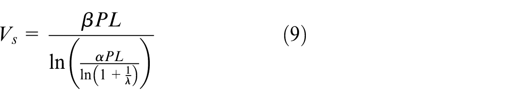
When the gas type, gas pressure and electrode material are determined,
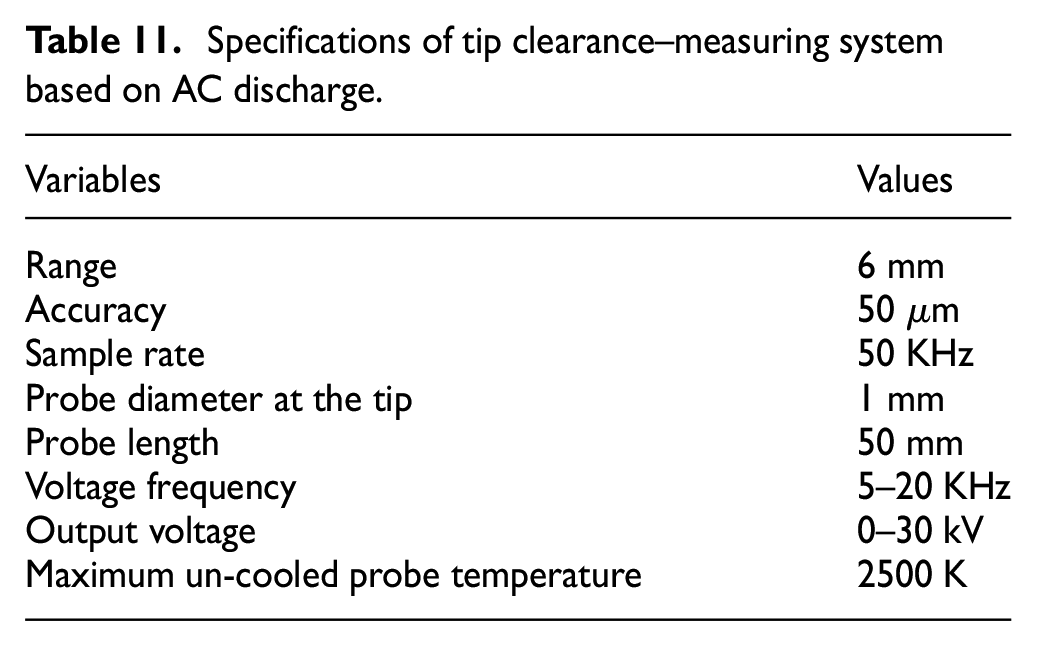
With the guide of this relationship, a measuring system based on AC discharge was developed. The diagram of the measuring system is shown in Figure 13. The measuring system is mainly composed of the power module, metal probe, blade model, voltage-measurement module and data-processing module. The power module adopts an AC voltage source, and its output voltage and frequency can be adjusted continuously. The metal probe is made using materials with good conductivity and heat resistance. The metal probe connected with high-voltage terminal of the power supply device is the anode, and the blade model connected with low-voltage terminal of the power supply device is the cathode. The gas discharge will happen between the probe and blade tip when the output voltage reaches breakdown voltage. The voltage measurement module is applied for measuring breakdown voltage, and all the data are analyzed and processed by the data-processing module. Specifications of the tip clearance–measuring system based on AC discharge are presented in Table 11.
Specifications of tip clearance–measuring system based on AC discharge.
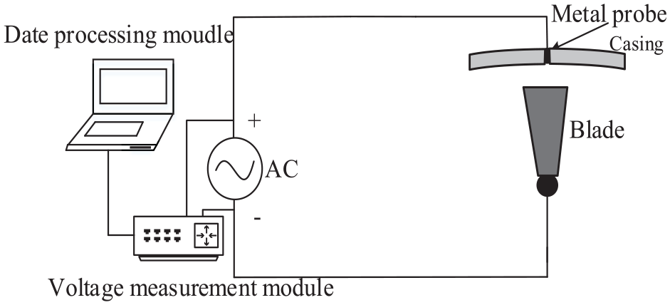
The diagram of the tip clearance–measuring system based on AC discharge.
At present, some preliminary achievements are obtained. First, theoretical analysis and the experiment of gas discharge are made to prove the feasibility of the measuring method. The relationship curve between the breakdown voltage and the blade tip clearance under standard atmospheric pressure air is presented in Figure 14. The system calibration and tip-clearance measurement are carried out on the test platform. With the characteristics of high heat resistance, low power consumption and high stability, the tungsten copper probe with planar structure is more suitable for measuring the tip clearance. Exploring through experiments, small fluctuations of temperature and humidity under normal temperature and atmospheric pressure environment have little effect on the experimental system that is shown in Figure 15. When the tip clearance is between 0 and 6 mm, the designed system has a high measurement accuracy, and its measurement error is within ±50 μm. Compared with the traditional probe method, the measuring method based on AC discharge not only effectively avoids the inconvenience of installation and operating difficulties which mechanical actuator brings but also improves the safety of the measurement system and eliminates dangers of collision and friction generated by the probe movement. In addition, it has the potential to be applied to high rotating speed situations. With the deeper study of this method, it can contribute to engine optimization design and safety control, meanwhile improve the efficiency and stability of the engine.
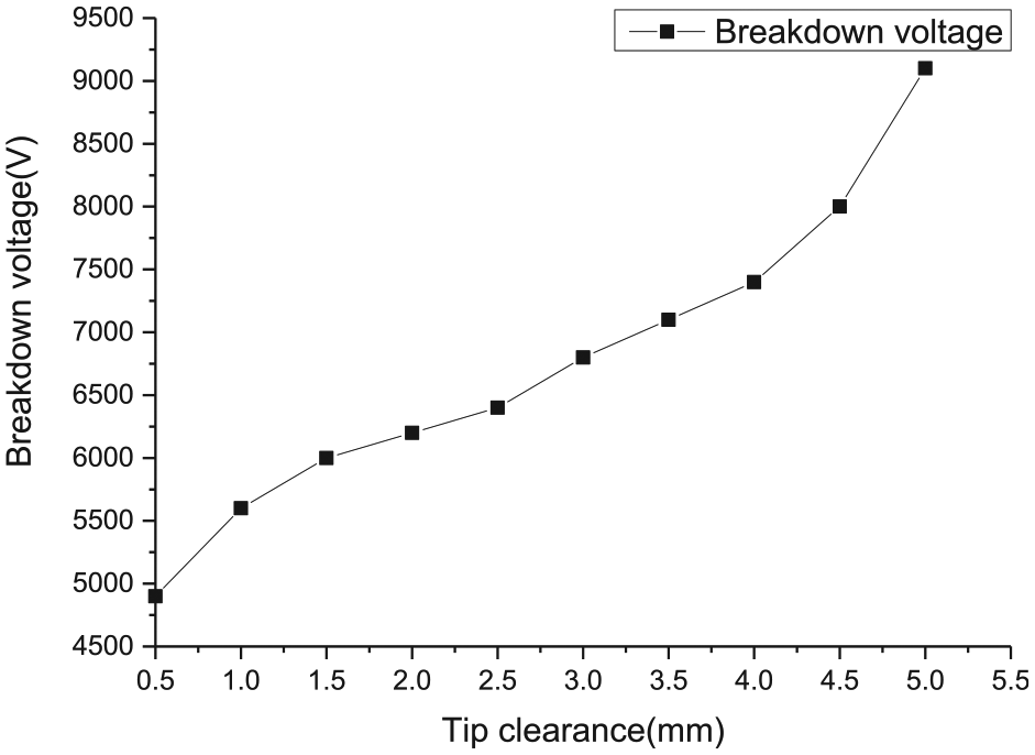
The relationship curve between the breakdown voltage and the tip clearance.
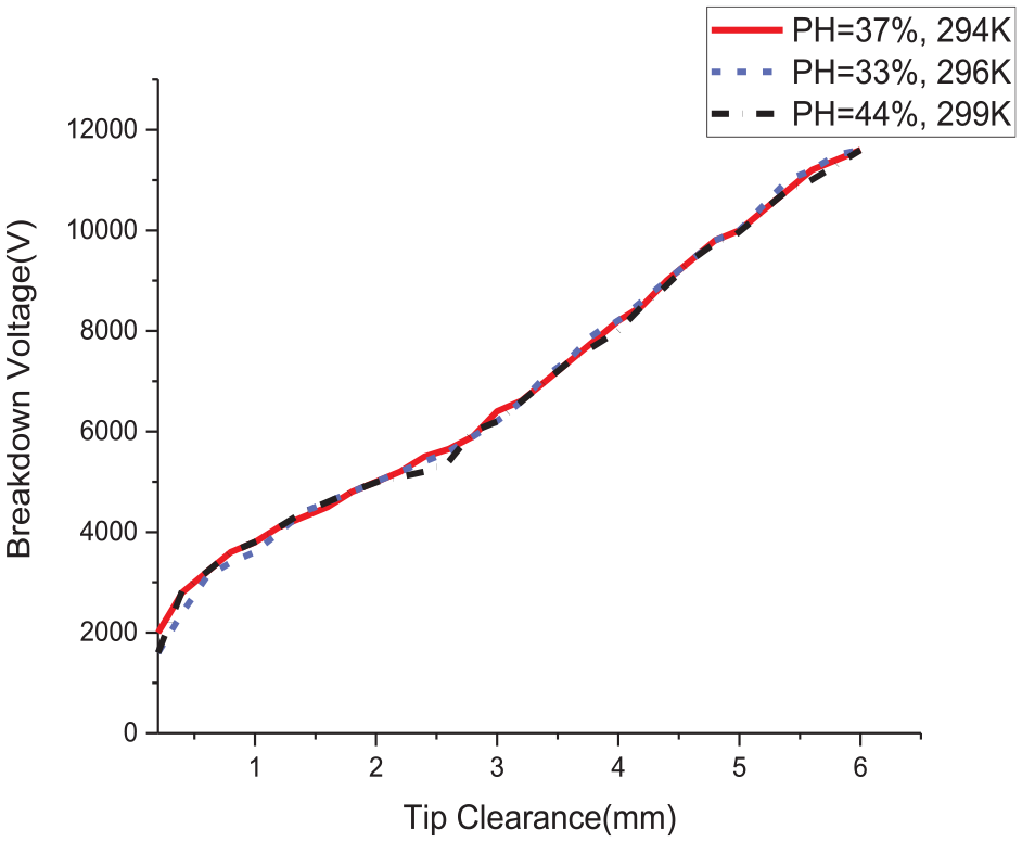
Experimental results with small fluctuations in temperature and humidity.
Conclusion
With the aforementioned analysis, a conclusion can be achieved that the blade tip clearance is an important parameter which may affect the efficiency, stability and safety of the gas turbine engine. Considering the significance of the blade tip clearance of an engine, several types of measuring methods are developed by researchers, and each method has its own characteristics. With the purpose of having a more intuitive look at the characteristics of each method, based on the information collected earlier, the optimal parameters of these research papers are shown in Table 12.
Specifications of different tip clearance–measuring methods.
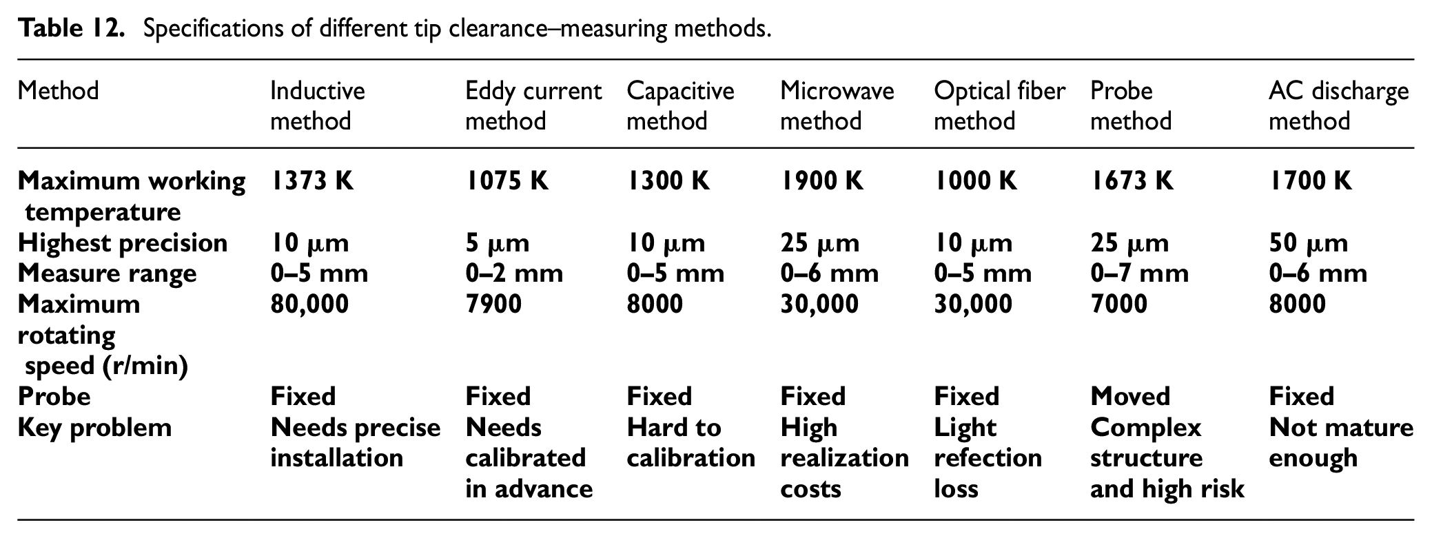
In the following paragraphs, some analyses and comments on the advantages and disadvantages of each theory are given.
The advantages of tip-timing method are that it overcomes some influencing factors in principle, such as the different rotor speeds and the changes of electrical signal amplitude. As for the disadvantages of this method, it depends on the probes used in the system. In addition, using this method will add a rotor speed synchronization sensor to the system which will reduce the system reliability.
With the advantages of long life, simple construction, high reliability and so on, inductive method is widely used in the measurement field of vibration and displacement. However, the low operating temperature and the need of precise installation greatly limit its application. But with the development of science and technology, there are some solutions proposed by researchers. For example, the working temperature of the sensors can be increased by using cooling air to cool the sensors while operating or by wrap the probe with high-temperature-resistant material. But these research works are in the laboratory testing phase, it is still a challenge to improve its heat resistance. In addition, by using multiple coils, the tip-clearance sensor can simultaneously detect the blade tip clearances at various positions which can increase its scope of application. A benefit from its working principle is that it can be used in a wide range of rotating speeds. This will facilitate its application to the measurement work of high-speed engines such as micro turbojet engines.
Due to the advantages of small size, low weight and high precision of the eddy current system, it has become a common measurement method in recent years. However, this method can only measure metallic materials, and the blade tip is required to have a certain thickness and its bandwidth cannot support the high-frequency sampling requirements of the engine’s tip-clearance measurement. As the output of the sensor varies with the blade tip shape, mounting state and environmental temperature, it needs to be calibrated in advance. With the decrease in coil size, the parasitic resistance increases, causing the sensitivity of the sensor to decrease. The effective solution to solve the disturbances and how to increase the bandwidth of the sensors will be the key research problem in the future.
The capacitive method has good heat resistance and has the advantages of simplicity, low cost and robustness. Its working temperature can be up to 1300 K. Currently, it is one of the most effective methods to measure the tip clearance of the gas turbine engine and has been widely applied by many industrial companies/institutions, such as RR, GE, PW, BMW-RR, ABB and NASA. However, low spatial resolution, short measurement range, unsuitable for high rotating speed situations and calibration requirements constrain the wide application of the capacitive sensors.
Microwave method can be applied in harsh environments of the engine, and microwave sensors are very robust and insensitive to contamination and the rotating speed. However, the wavelength of the microwave would change with the blade thickness, which would affect the measuring accuracy. Currently, the hollow waveguides at the sub-millimeter wavelengths is almost impossible to achieve, and the realization cost for higher accuracy is very expensive. But predictably with the technology development and the cost reduction, the approach may be a promising measurement method in the future.
The advantages of optical fiber method are stable performance, strong resistance to electromagnetic interference ability, high measuring accuracy and non-contact measurements; the method has become the focus of development in recent years. However, compared to other tip clearance–measuring sensors, the sensors have expensive realization cost, contain elements that are sensitive to calibration and are easily affected by contamination. With the effect of oil stains on the blade tip surface, which would cause the light reflection loss, thereby decrease the sensor accuracy. Therefore, in order to improve its performance, the light reflection loss is a major problem to solve.
The probe method is employed for the clearance measurement of the gas turbine engine in the early stage; sensors based on the probe method have a simple working principle, and they can work in harsh environment of the engine. However, unsuitable for high rotating speed situations, complex structure, high risk caused by probe moving and slow response time are the main defects of the probe method. Although the probe method has been replaced gradually by new technology, for its relatively high measurement accuracy, it can still serve as a reference for other methods.
The original tip clearance–measuring method based on AC discharge not only has the same advantages with the traditional probe method but also overcomes many defects of the spark discharge method. The measuring system designed preliminarily has good measurement accuracy and has the potential to be applied to high rotating speed situations; with the deeper research on this method, it will have a broader application prospect in the future.
These typical methods all have some limitations, which restrict their applications. But with the technology development and the further researches on the tip clearance–measuring method, the practicability and applicability of these methods will be improved greatly. Some methods which are more suitable and more reliable will be developed for the optimal design of the engine. These can contribute to enhance the performance, efficiency and safety of the gas turbine engine.
Footnotes
Declaration of conflicting interests
The author(s) declared no potential conflicts of interest with respect to the research, authorship and/or publication of this article.
Funding
The author(s) disclosed receipt of the following financial support for the research, authorship and/or publication of this article: This work is supported by the Natural Science Foundation of China (grant no. 51406083), and the Fundamental Research Funds for the Central Universities (grant no. NS2018017).