
Abstract
In this paper, a tuning procedure of the parameters of fractional order proportional integral controller is presented for time delay system with arbitrary order. On the basis of obtaining stable solution space by utilizing some stability-domain boundaries which include real-root boundary and σ-stability boundary, the optimal solution can be achieved by applying specific frequency-domain specifications which include gain crossing frequency, phase margin, and robustness constraint. Using the same synthesis by traversing phase angle and phase margin in a given interval, the complete solution space of gain crossing frequency can be obtained and visualized, which is equivalent to demonstrate the complete solution space of optimal parameters of fractional order proportional integral controllers. As a comparison, the tuning procedure of the parameters of integral order proportional integral derivative controller is also discussed. At last, the proposed algorithm is validated by numerical simulation and experimental illustrations. The results show the robustness and advantage of the proposed fractional order proportional integral controller over other controllers.
Introduction
Due to the merits of fractional calculus in the area of modeling and controlling complex dynamical processes, it gradually replaces integer order calculus as one of the research focus in the control field. 1 However, compared to integer order controller, the introduction of fractional calculus operators increases the design difficulty of fractional order controller, which affects its promotion in the practical application. To overcome this problem, the tuning method of the parameters of fractional order controller has attracted lots of attention in recent years.
For simplifying the complexity of a control system, a simple methodology for the tuning of integral order proportional integral derivative (IOPID) controllers was first introduced by Barbosa et al.; 2 the problem of configuring proportional integral derivative (PID) parameters is transformed into determining the order and gain crossing frequency of ideal open-loop transfer function, which can be realized by some frequency-domain or time-domain specifications. Based on this, the application of this method is further extended to fractional order PID (FOPID) controller, in which the fractional orders can be taken as two degrees of freedom (2-DOF) to enlarge the limitation of such method.3–5 Moreover, some advanced technologies are further considered, such as the idea of 2-DOF PID controller is introduced to ensure disturbance rejection, 6 or Smith predictor is introduced to overcome the influence of longtime delay in the system. 7 However, regardless of how advanced the chosen method is, system performance will only be determined by the parameters of the ideal transfer function, which loses flexibility of the method. From another point of view, to achieve the robustness of the system, some studies that focused on the flat phase method are first introduced 8 to obtain optimal parameters of fractional order controller with several frequency-domain specifications. However, this method only considers the characteristics in the medium frequency band of Bode diagram, which neglects the requirement for the interference suppression capability in high-frequency band and low-frequency band. In order to overcome this problem, two more specifications are added based on sensitivity and complementary sensitivity analysis methods. 9 Based on this method, a generalized iso-damping approach is proposed to define the invariance of the phase margin with respect to the free parameter variations, 10 which supplies a more comprehensive analysis for the controller to suppress uncertainties. Although such methods provide an exact resolution process for finding the parameters of an FOPID controller, some of the predefined parameters in the algorithm are difficult to select, such as phase margin and gain crossing frequency. With this in mind, the selection of feasible or even optimal predefined parameters has received widespread attention recently. For example, differential evolution algorithm 11 or dynamic programming method12, 13 is adopted to get a desired solution in a specific area, and the original equality constraint is modified to an inequality constraint to increase the searching probability of the feasible solution. However, the determination of initial search point and search space is a difficult topic. Therefore, the main task at present is, “How to determine an appropriate search space of controller parameters?”
For solving the problem presented above, some researchers focused on applying Pontryagin and Hermite–Biehler theorems to derive theoretical bounds on controller parameters; the collection of the parameters restricted by these bounds can form an appropriate search space. 14 Moreover, an extension of Hermite–Biehler theorem has been found with a combination of the generalized Kharitonov theorem to determine the entire set of stabilizing proportional integral (PI) parameters and obtain robustly stabilizing controller. 15 However, the procedure of finding the optimal solution from a given search space is not discussed. Subsequently, some frequency-domain specifications and stability-domain boundaries in complex plane 16 are both considered to determine the appropriate search space, in which the optimal solution can be found. 17 Moreover, such methods are popularized and applied in the system with other controllers, such as FOPD controller 18 or FO[PI] and FO[PD] controller,12, 13 which also validate the effectiveness of the method. However, there still remain two questions. First, these methods only consider the assignment of closed-loop poles on the imaginary axis, and then find the parameters of fractional order controllers to satisfy specific frequency-domain specifications with desired poles in the closed-loop system. Remarkably, on one hand, the solution space obtained in these methods is incomplete, because the desired closed-loop poles on left half plane (LHP) are not considered. On the other hand, the systems with desired frequency-domain characteristics may not contain the closed-loop poles on imaginary axis, which means the frequency-domain specifications and stability-domain boundaries cannot be satisfied simultaneously, namely, these methods have certain limitations. Second, these methods are only applied to a few plants, so it is necessary to extend them to more general areas and enhance their applicability.
In order to address and overcome the challenges presented above, this paper provides its main contributions as follows:
A method is proposed to determine the complete solution space of the parameters of FOPI controller for arbitrary integer order plus time delay system.
The proposed method, as an extension of the work 17 by extending the stability-domain boundaries from imaginary axis to the whole LHP, ensures that the optimal solution of the parameters of FOPI controller can be found for arbitrary integer or fractional order plus time delay system to satisfy desired frequency-domain specifications and stability-domain boundaries simultaneously, while the previous one can only be suitable for parts of such system. For the same reason, the proposed method has a greater probability of obtaining the global optimal solution than the previous one.
Gain crossing frequency is an important parameter in the application of frequency-domain specifications, which can be determined by automatic calculation in the proposed method other than by area searching in the traditional method. It turns out that the proposed method is more convenient than the former.
Numerical simulation and experimental results are presented to validate the advantage of the proposed method.
The content of this paper is organized as follows. The structure of the control system is presented in the next section, then the stability-domain boundaries are applied to determine the stable solution space for the parameters of FOPI controller, based on which the frequency-domain specifications are applied to determine the optimal solution. After that, the complete solution space of gain crossing frequency is collected, which is equivalent to demonstrate the complete solution space of parameters of the FOPI controller. In the “Generalization of the method with an example” section, an example is demonstrated to generalize the proposed algorithm both for FOPI controller and IOPID controller. In the “Simulations” and “Experimental validation” sections, numerical simulations and experiments have been validated in a variety of systems; the results all show the advantages of the proposed method.
Procedure analysis
The structure of the system
Considering a closed-loop system shown in Figure 1,
where
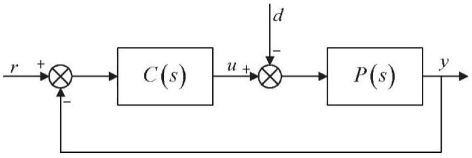
Structure of the system.
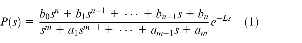
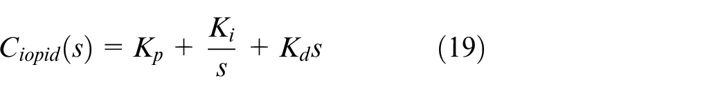
In this paper, the proposed controller

where
Combining equations (1) and (2), the transfer function of closed-loop system can be obtained
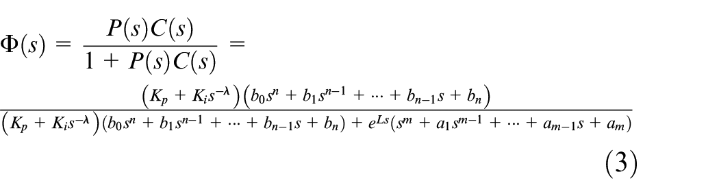
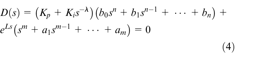
According to equation (3), the characteristic equation
Determine stable solution space by stability-domain boundaries
As we know, the design target of the controller is to achieve the best performance while ensuring the stability of the system. The composition of all feasible controller parameters which meets the requirements mentioned above can be called a stable solution space. For the previous researches, real-root boundary (RRB) and complex-root boundary (CRB) are applied as the stability-domain boundaries to acquire the stable solution space of the controller. However, the closed-loop poles can only be assigned on the origin or imaginary axis in this case. Therefore, the stable solution space should be obtained by assigning the poles on the whole LHP, which can be shown in Figure 2.
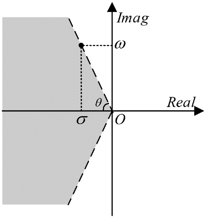
Stable region determined by RRB and σ-stability boundary.
In Figure 2, the gray filled part represents the stable region; the dashed line represents the boundary of stable region;

where
According to Figure 2, the stability-domain boundaries are described as follows:
RRB: The closed-loop poles configured on positive real axis will undoubtedly result in the instability of the system; thus, we can denote the origin for RRB, which can be described as
σ-stability boundary: The closed-loop poles assigned on LHP can be expressed by
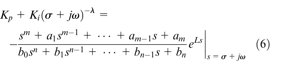
where
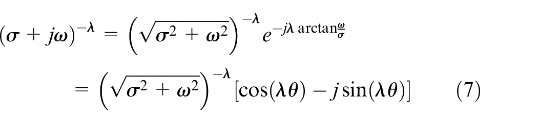
Taking the real part and the imaginary part of equation (6), equation (8) can be obtained
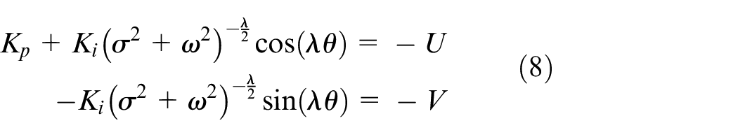
where
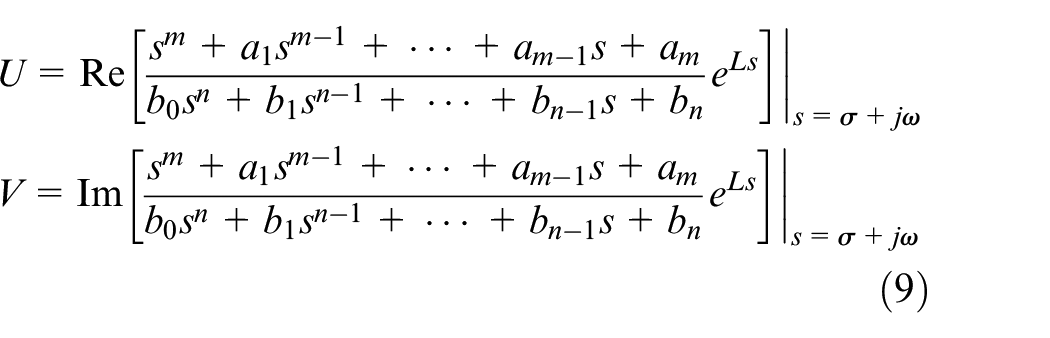
From equations (8) and (9), equations (10) and (11) are obtained
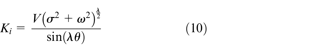

By setting
Determine optimal solution by frequency-domain specifications
On the basis of the former section, the scope of feasible solution space should be narrowed to find the optimal solution of FOPI controller, then the best performance of the system will be acquired. In order to accomplish this target, specific frequency-domain specifications will be described in this section. Considering the open-loop transfer function
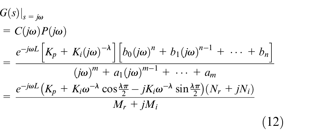
where
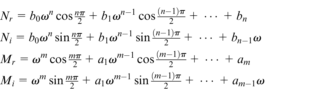
Then, by following two specifications, gain crossing frequency and phase margin, equations (13) and (14) can be described
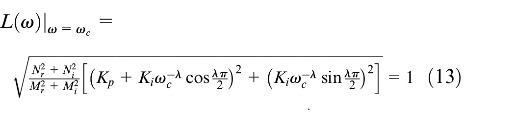
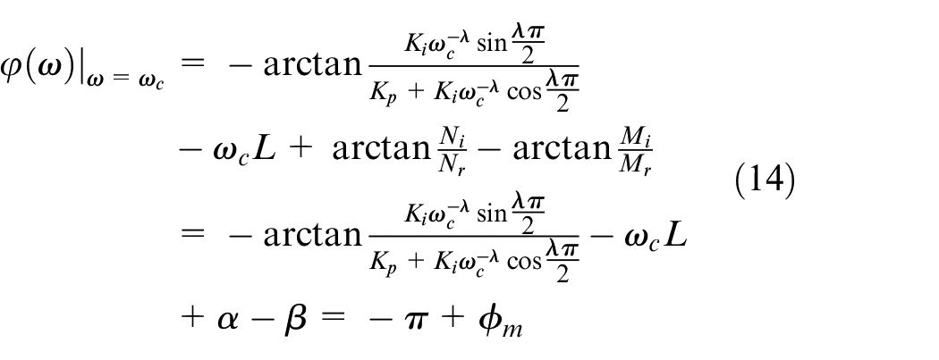
where
According to equation (14), with fixed

where
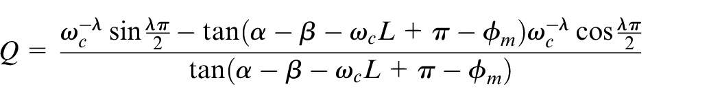
Substituting equation (15) into equation (13) to eliminate
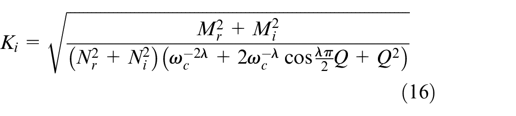
By setting
Among the above discussion, to acquire the optimal solution of FOPI controller,
In addition, fractional order
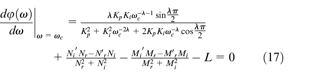
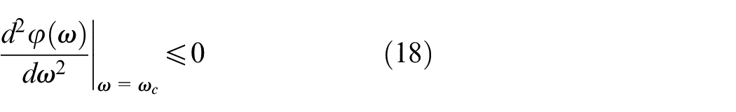
Substituting all the intersections on the sub-optimal stability curve into equations (17) and (18), the point
Complete solution space of gain crossing frequency
As can be seen from the above discussion, with a fixed phase margin
To confirm the advantage of the proposed algorithm by comparison, an FOPI controller mentioned in Chen et al.
17
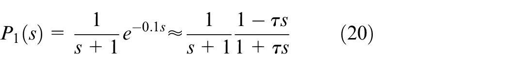
is discussed; besides, the IOPID controller is also discussed by following the same synthesis in this paper. As the control plant subject to such controllers,
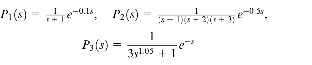
Here,
Both the parameters of FOPI and IOPID controller have the characteristics of three degrees of freedom (3-DOF), so the derivative gain
Analogous to
where
According to
where
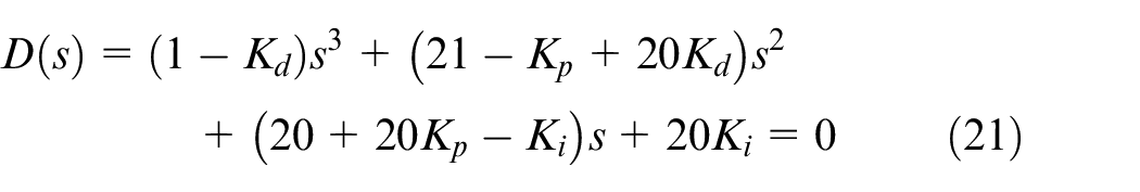
According to equation (21), Table 1 can be listed by the Routh–Hurwitz stability criterion.
Routh–Hurwitz criterion.
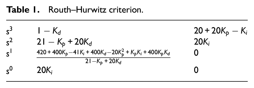
Considering the necessary condition of the Routh–Hurwitz stability criterion—namely, the coefficient of equation (21) needs to be all positive—equation (22) can be obtained as follows
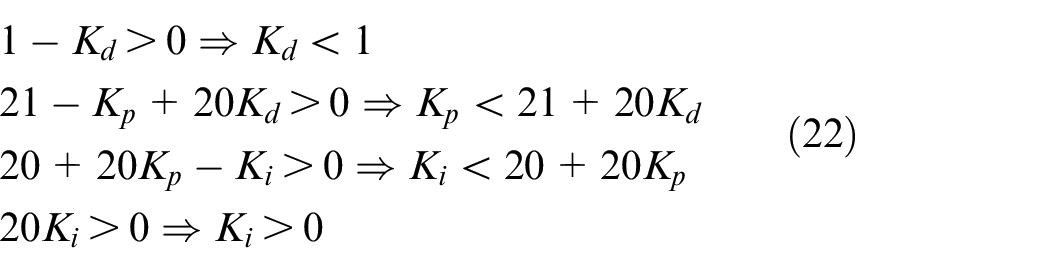
Then considering the sufficient condition of the Routh–Hurwitz stability criterion—namely, all elements in first line of Table 1 should be positive—one can conclude that
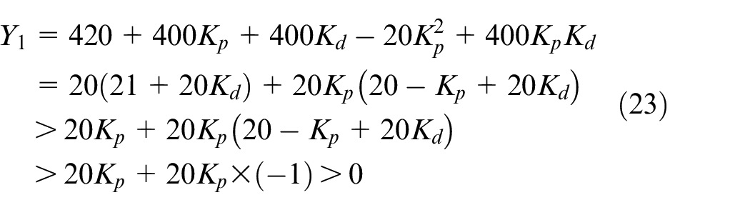

Obviously, to ensure that
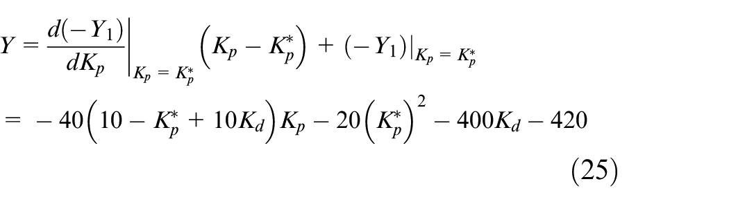
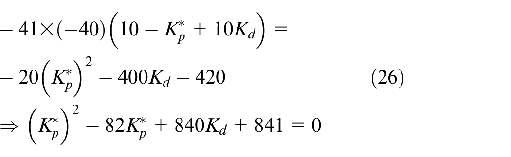
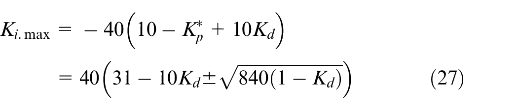
where
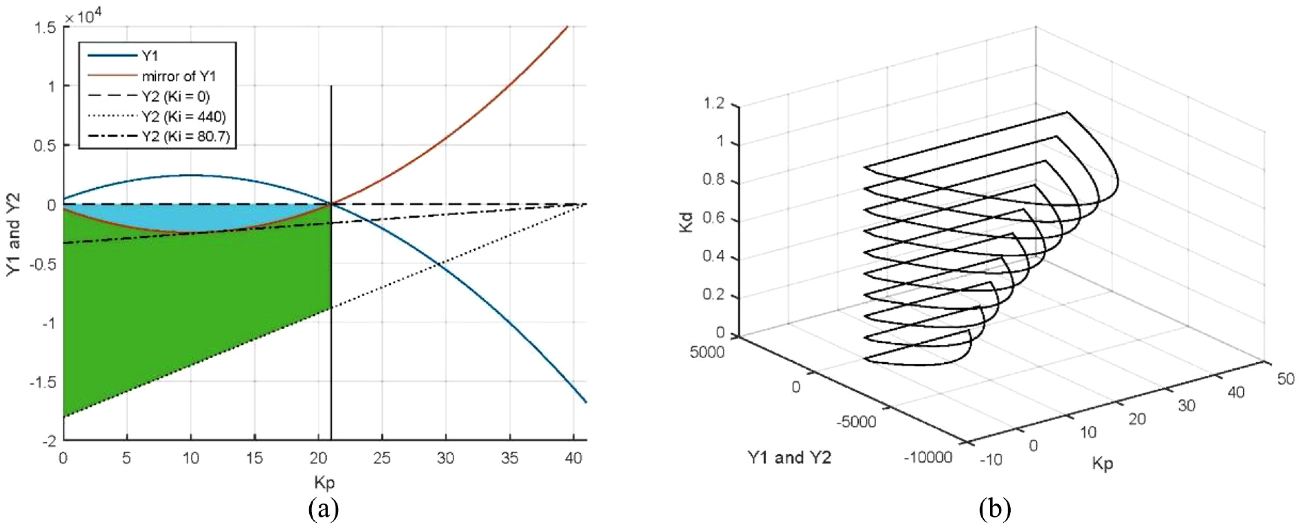
Stable region of Kp, Ki, Kd in IOPID controller: (a) stable region while Kd = 0 and (b) stable regions while
Obviously, only one solution of equation (27) is acceptable for the reason that
Generalization of the method with an example
In this section, the proposed method is generalized with an example; the corresponding flowchart is shown in Figure 4.
Step 1. Select first order plus time delay system
Step 2. According to equations (15) and (16) in the “Procedure analysis” section, with the range of gain crossing frequency
Step 3. Take
Step 4. The point on the sub-optimal stability curve which satisfies the robustness constraints has been presented as the red dot in Figure 7(b). It is the robustness point. The corresponding parameters
Step 5. With the range of
Step 6. Replace
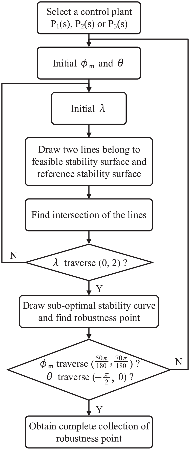
Flowchart of the control algorithm.
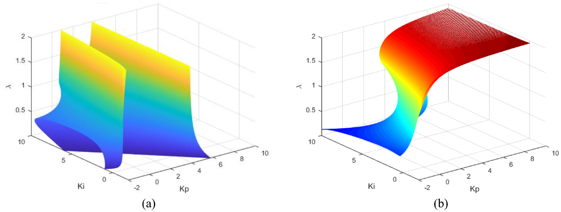
(a) Feasible stability surface and (b) reference stability surface.
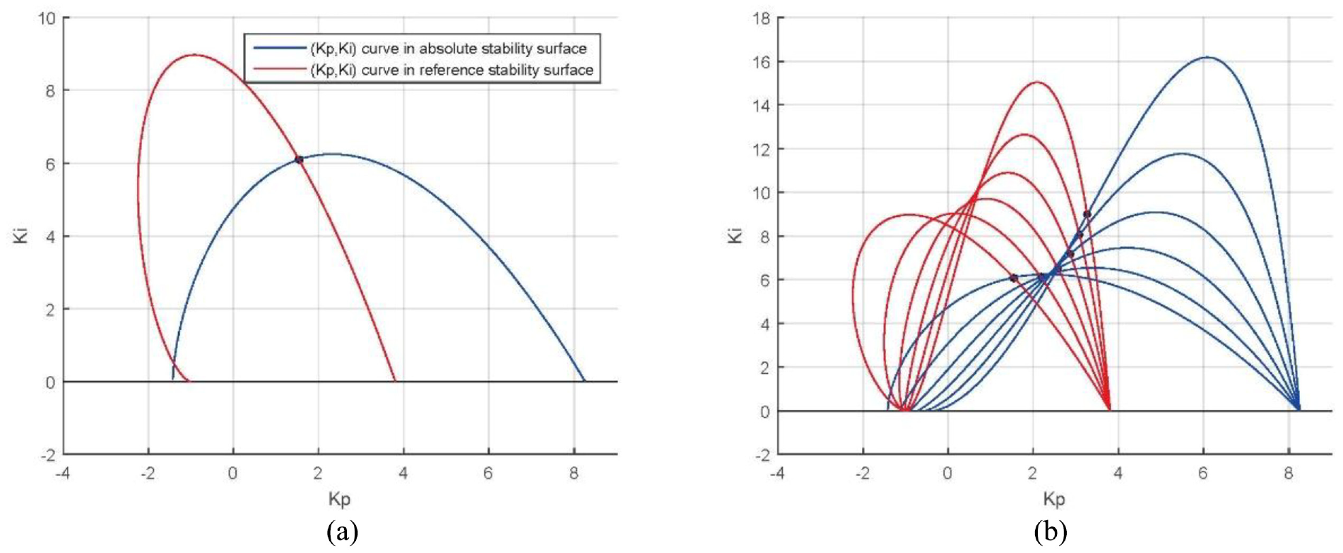
Intersection point of (Kp, Ki) with (a) λ = 0.5 and (b)
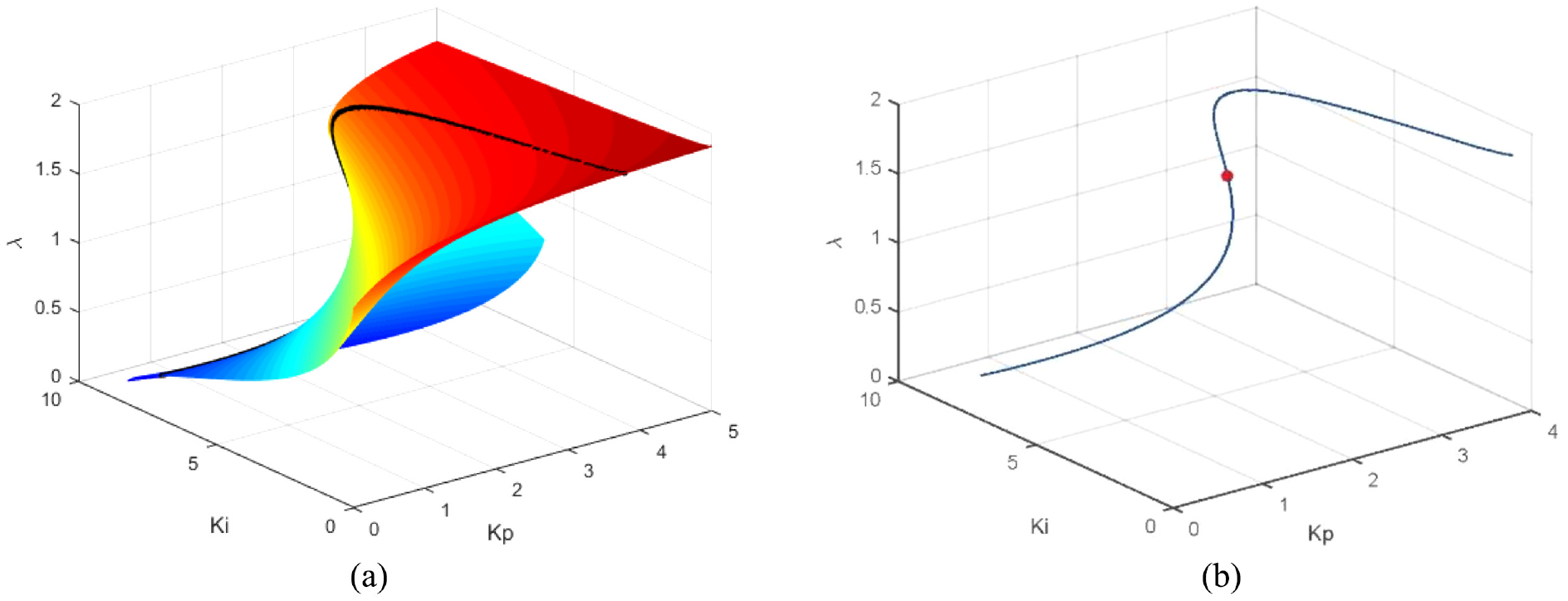
(a) Sub-optimal stability curve and (b) robustness point.
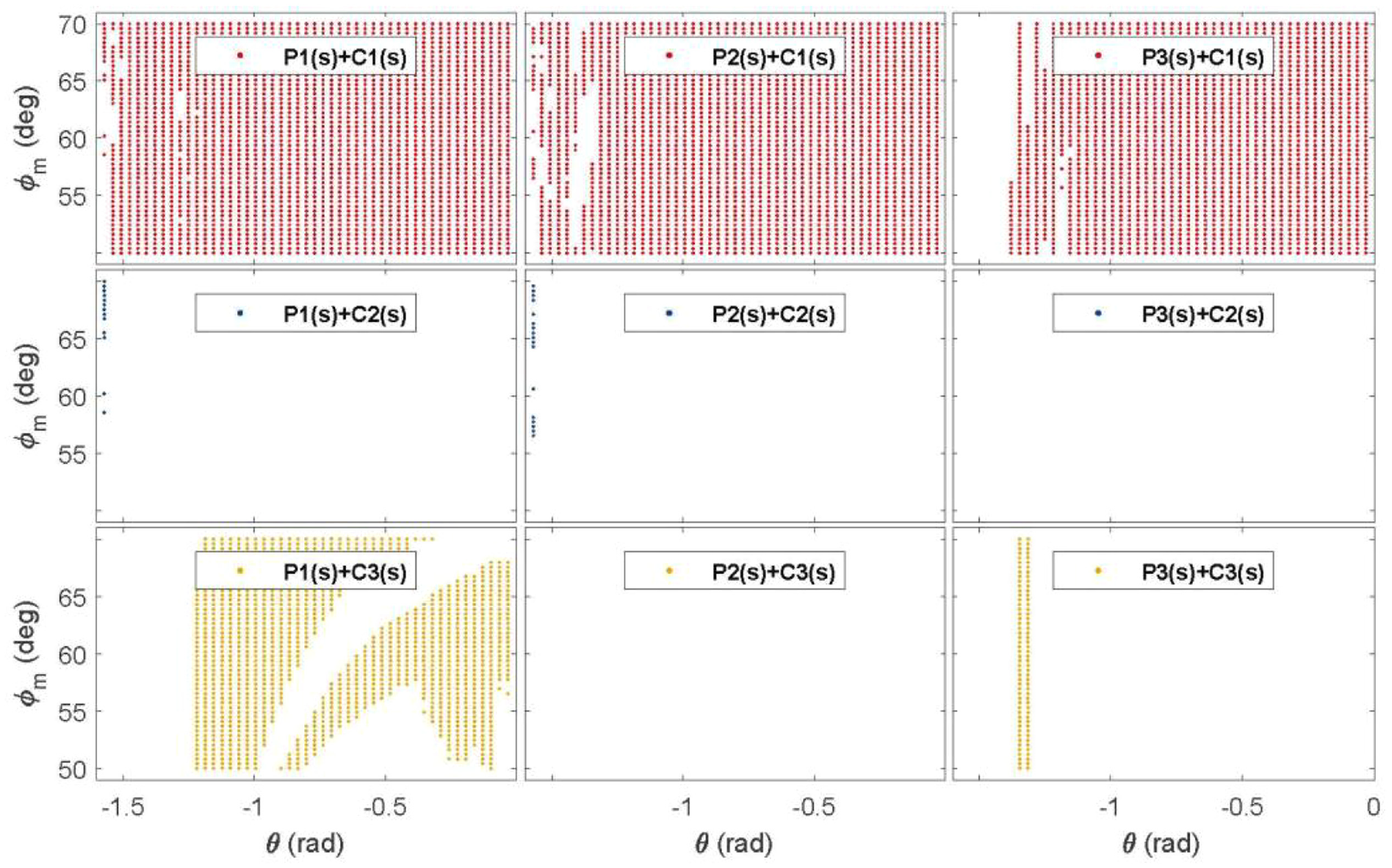
Complete solution space of
As can be seen from Figure 8, the complete collection of robustness point in the first line shows the proposed algorithm greatly enlarges the range of the desired parameters by comparison. The second and the third lines show that the robustness point cannot be found in all control systems with different plants
Simulations
In this section, the designed FOPI controller is validated with different control plants by numerical simulation illustrations.
In this case, phase margin
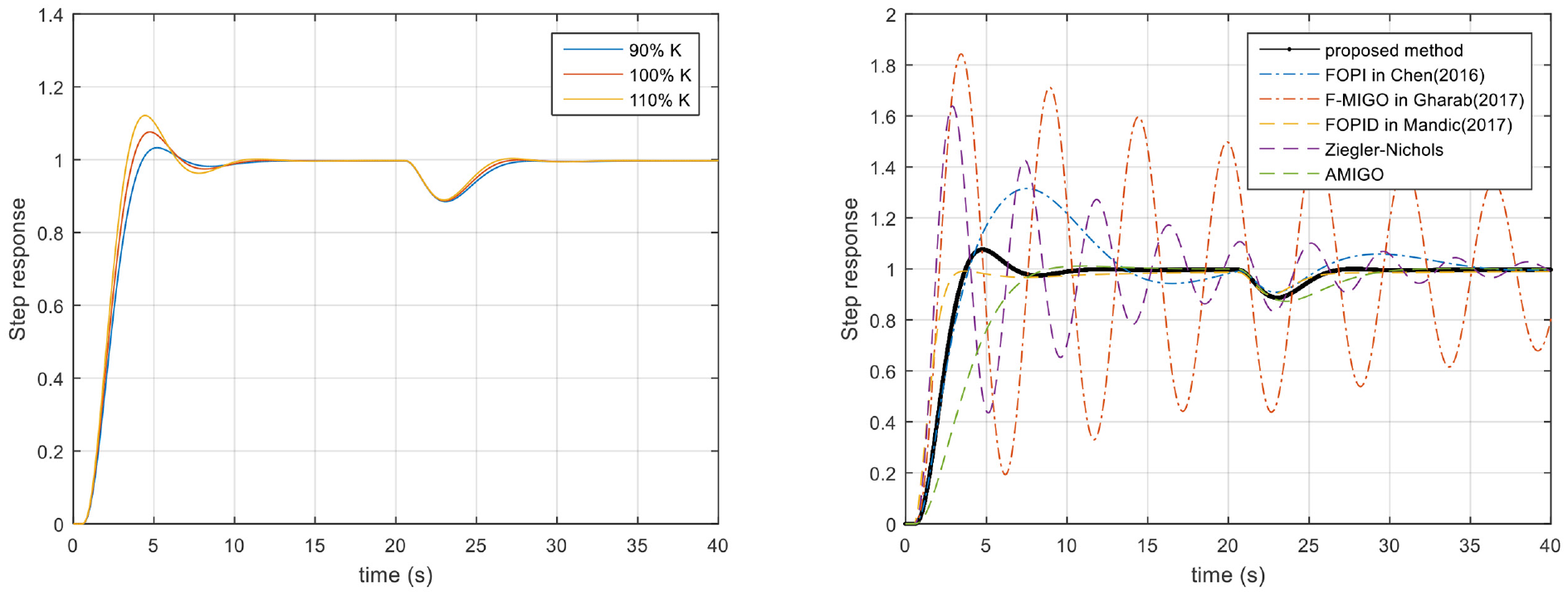
The open-loop Bode diagram of the proposed algorithm is presented in Figure 9(a); the step responses and disturbance (magnitude 1 step) rejection responses are presented in Figure 9(b), and the robustness performances are illustrated with
where
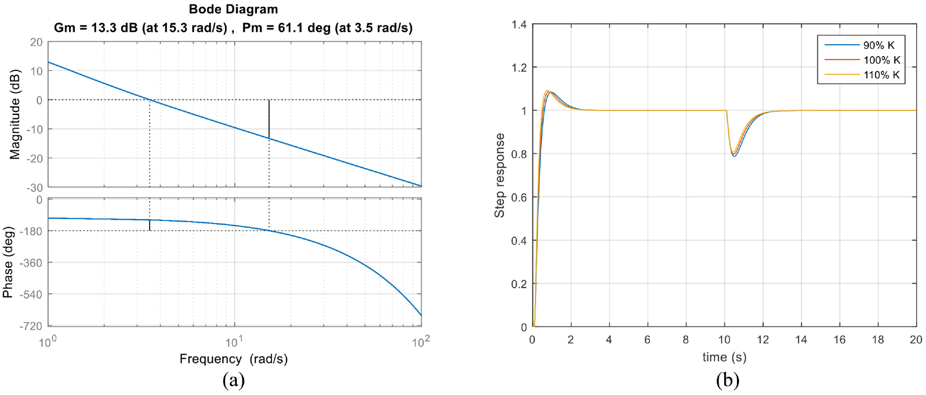
Bode diagram and step response with loop gain variations: (a) open-loop Bode diagram and (b) step response.
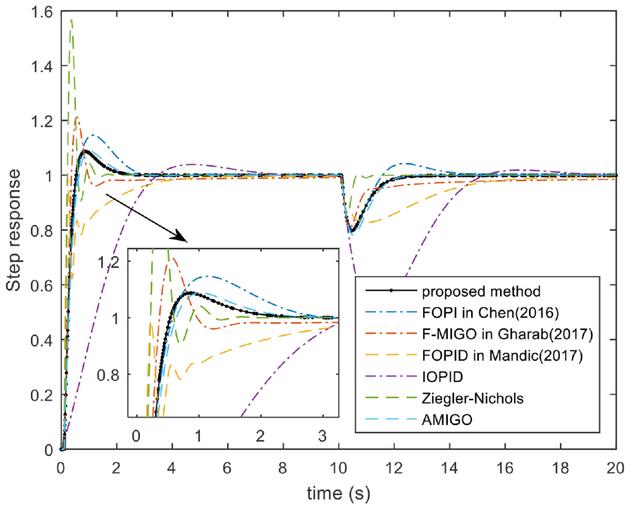
Contrast simulations of different controllers with
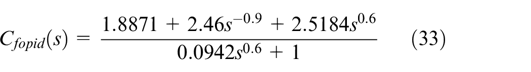
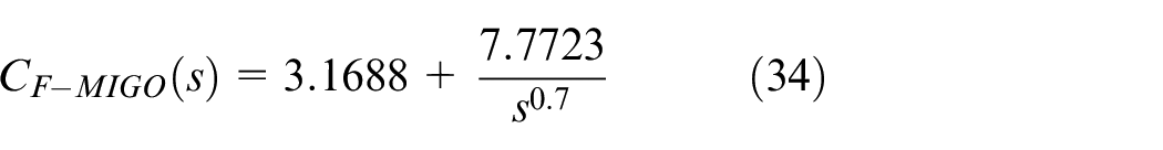
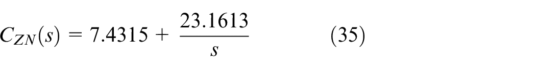
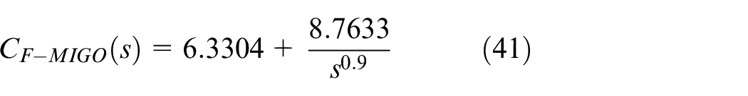
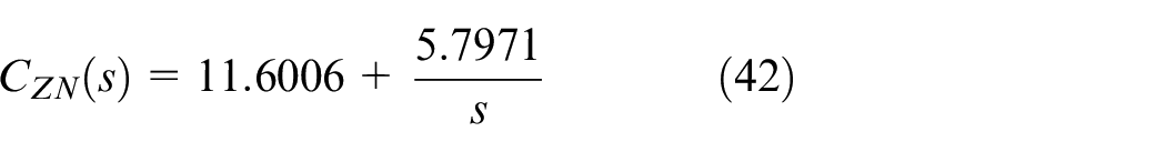
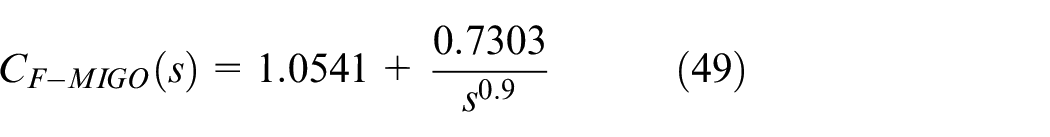
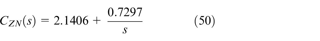
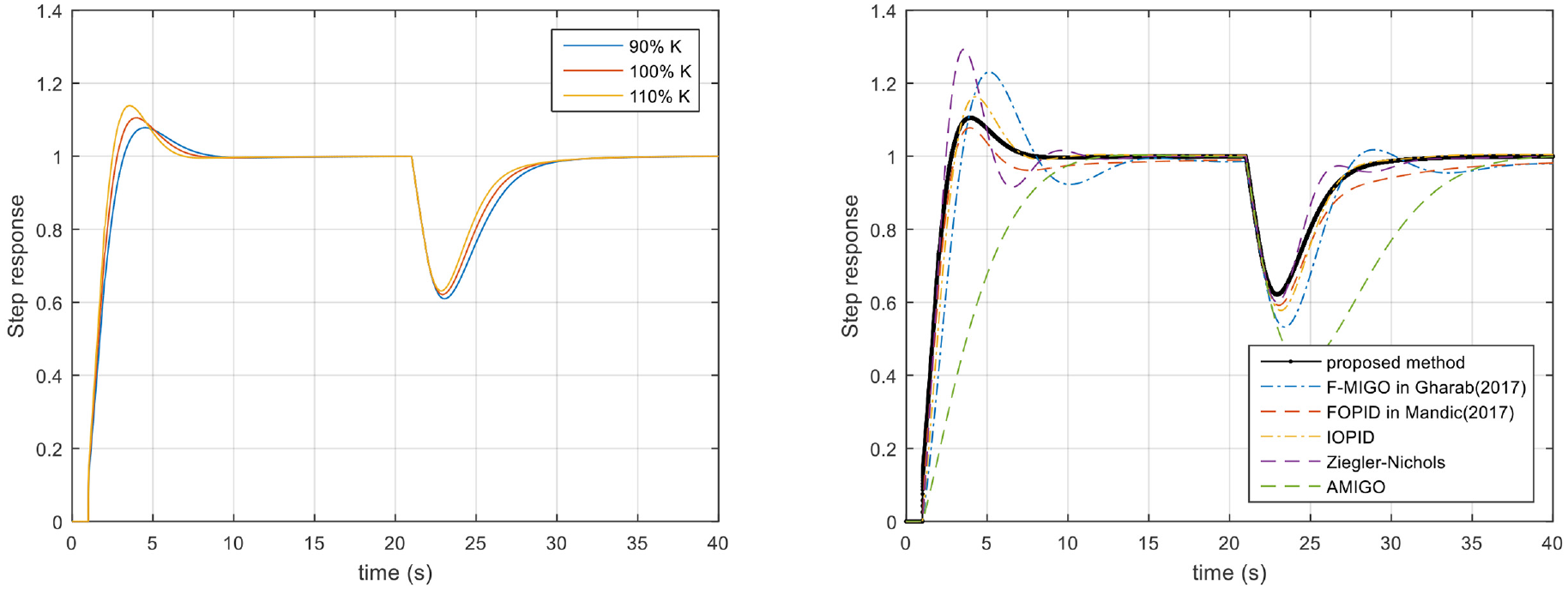
The controllers designed by F-MIGO, AMIGO, Ziegler–Nichols methods, and the FOPID controller discussed in Mandić et al. 20 are shown in equations (33) to (36)

In this case, the IOPID controller cannot be obtained because no robustness point exists on the second line and third row of Figure 8. The FOPI controller proposed in this paper and Chen 17 can be designed as equations (37) and (38) by selecting a robustness point on the first and second rows of second line in Figure 8
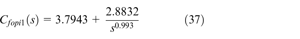
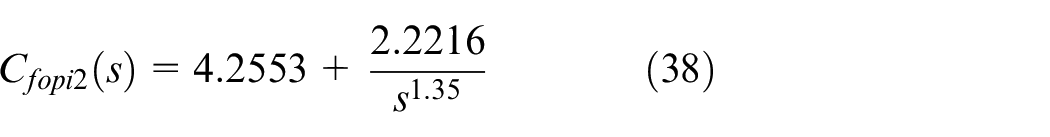
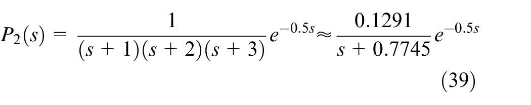
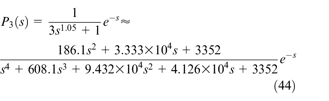
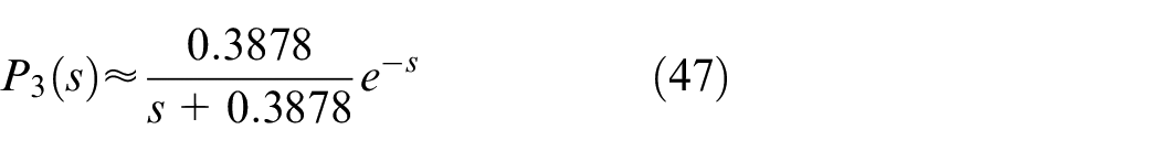
Considering that equations (31) and (32) are applicable for first order plus time delay system,

Step response with loop gain variations and contrast simulations of different controllers with
In this case,
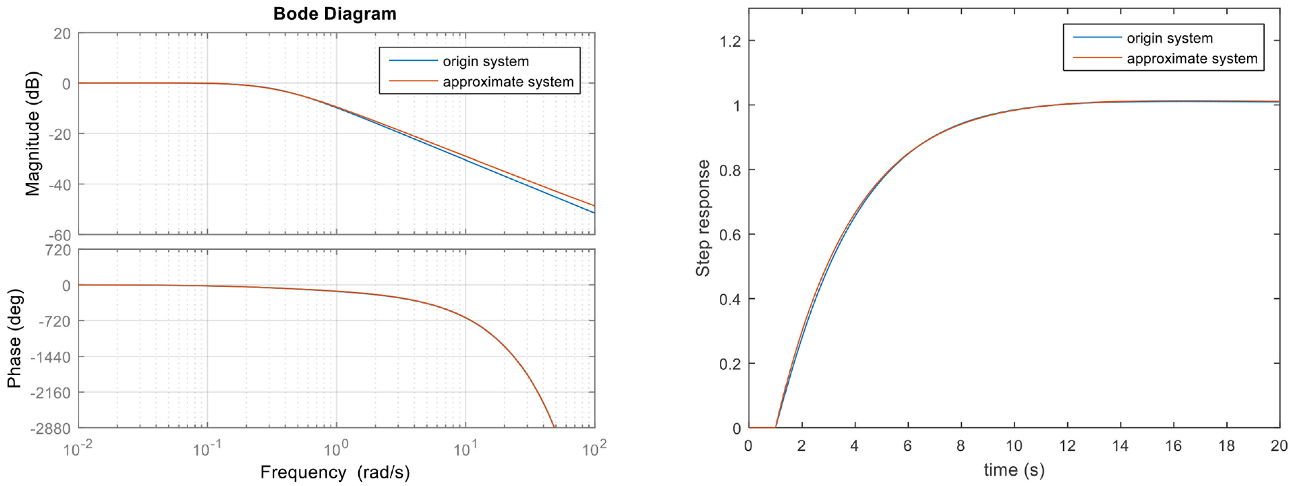
Comparison of
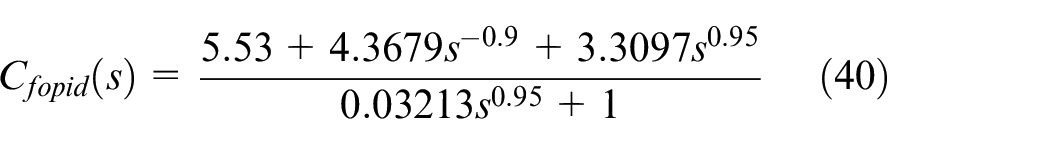
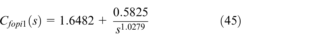
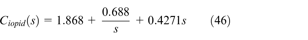
As can be seen from Figure 8, the FOPI controller discussed in Chen et al. 17 cannot be obtained because no robustness point exists on the third line and the second row. Then the FOPI controller proposed in the paper and IOPID controller can be designed as equations (45) and (46) by selecting a robustness point on the first and third rows of the third line of Figure 8
Considering that equations (31) and (32) are applicable for first order plus time delay system,
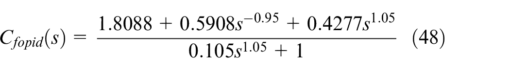

Step response with loop gain variations and contrast simulations of different controllers with
For evaluating the advantage of the proposed algorithm compared with other methods, the integrated time absolute error (ITAE) index and the overshoot of step response
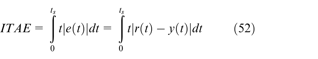
where
Comparisons of different methods.
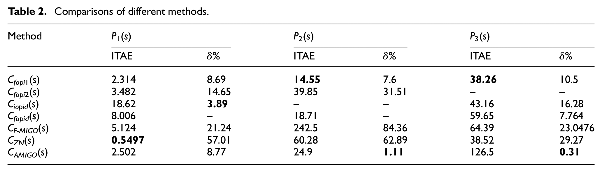
As can be seen from Table 2, the best ITAE and overshoot for each systems are shown in bold, which represent for they can not reach optimal result at the same time. Therefore, a compromise must be sought. For the first order plus time delay system
Experimental validation
Hardware-in-the-loop simulation platform introduction
In this section, the proposed algorithm is validated in permanent magnet synchronous motor (PMSM) servo control system. Figure 14 shows the hardware-in-the-loop simulation platform. The MATLAB/Simulink software in personal computer is used to edit the proposed algorithm, and cSPACE module is used to download the edited algorithm to the control board. The main function of the control board is to drive the PMSM; its specific model is TMS320F28335. Parameters of PMSM are presented in Table 3. A coaxial DC motor is used as the load.
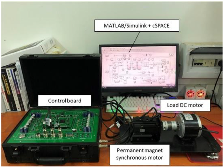
Hardware-in-the-loop simulation platform.
Parameters of PMSM.
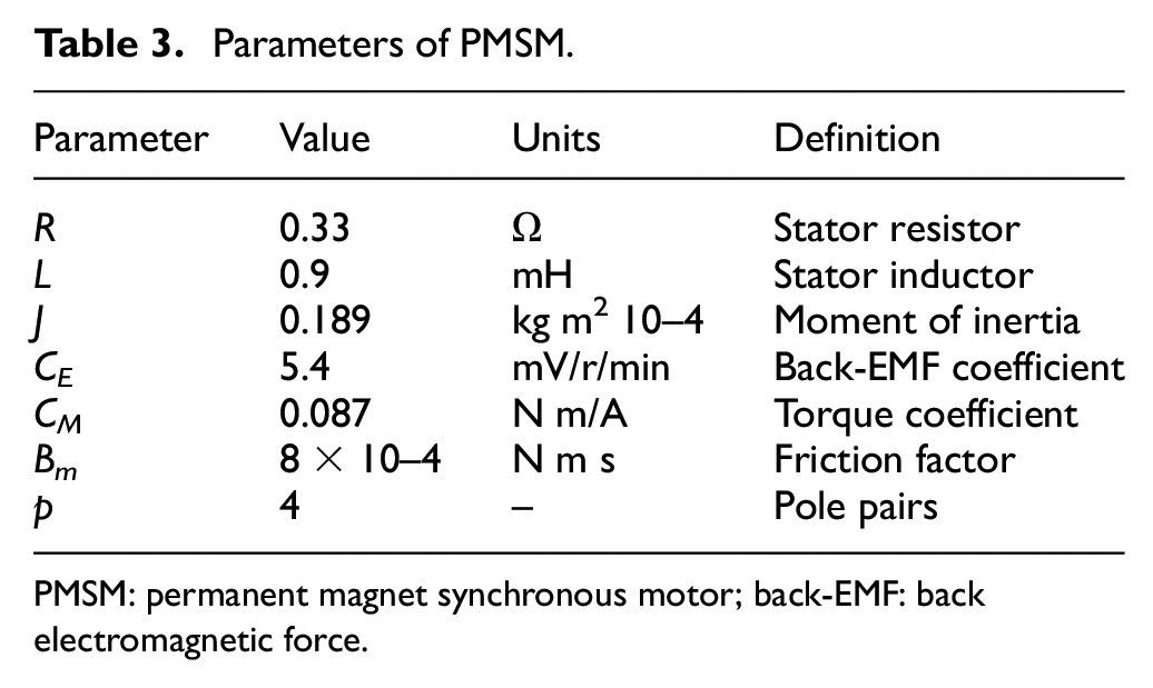
PMSM: permanent magnet synchronous motor; back-EMF: back electromagnetic force.
Experimental results
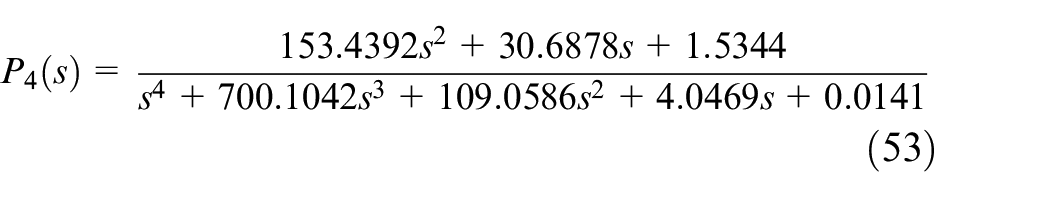
According to Table 3, the object model of the system can be obtained as follows
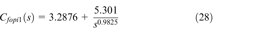
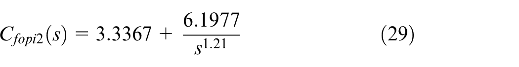
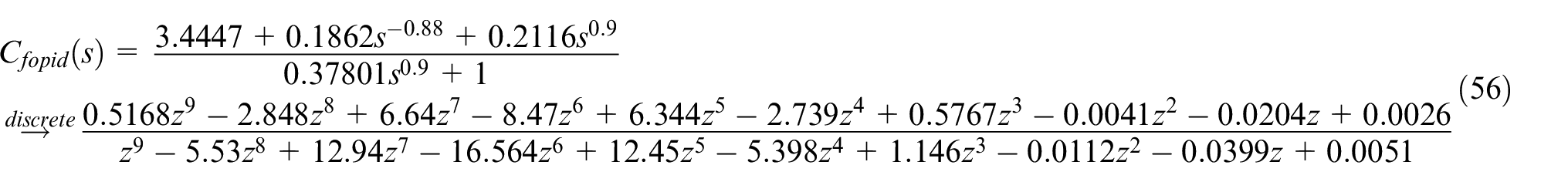
In order to satisfy the experimental conditions, the fractional operator in fractional order controller is discretized by impulse-invariant discretization method. 21 Based on equation (53), four fractional order controllers are designed by the algorithms proposed in this paper;17,19,20 then setting sampling period to 0.000625 s, the discrete transfer function of those controllers can be described as follows


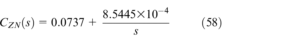
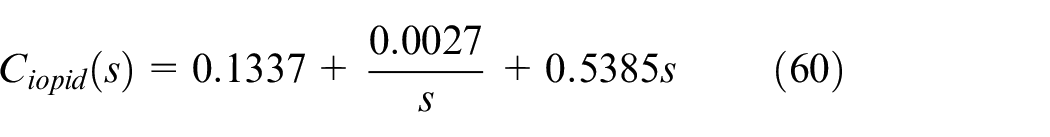
Besides, other three integer order controllers based on Ziegler–Nichols, AMIGO, and the proposed method are designed as follows

Using the proposed FOPI controller, the open-loop Bode diagram can be shown in Figure 15(a). The gain crossing frequency and phase margin are 0.00601 rad/s and 50°, respectively. The step responses are presented in Figure 15(b), and the robustness performances are illustrated with
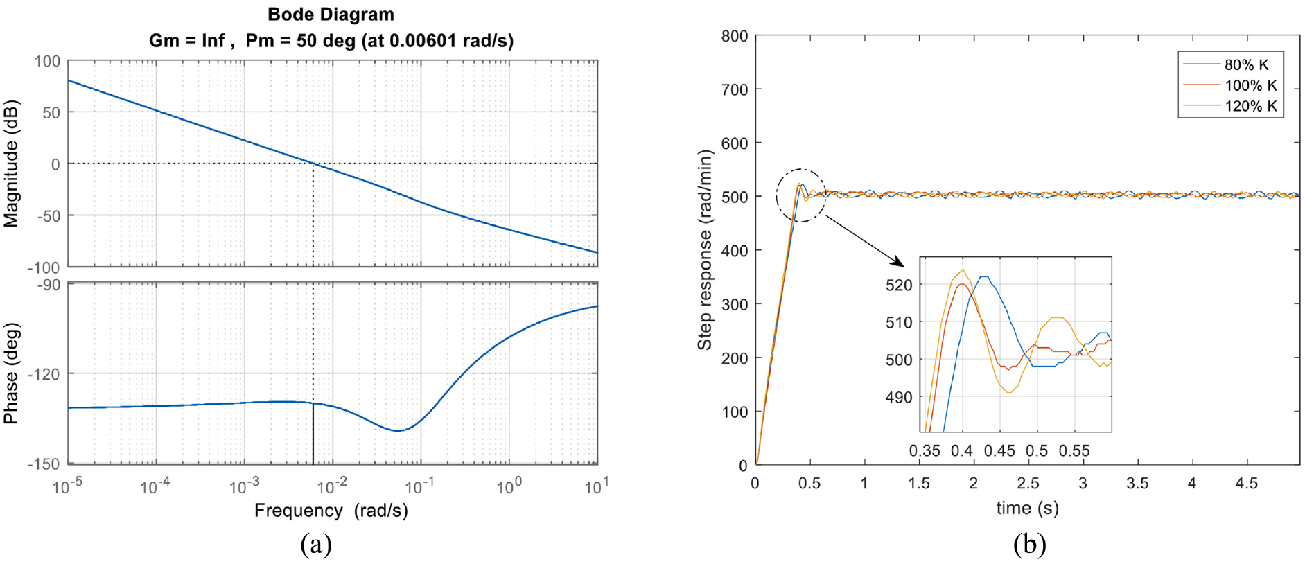
Bode diagram and step response with loop gain variations: (a) open-loop Bode diagram and (b) step response.
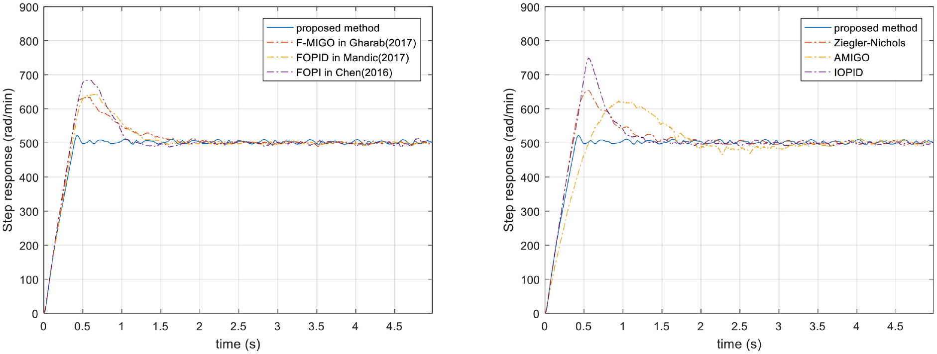
Contrast experiments of different controllers with
Comparisons of different methods.
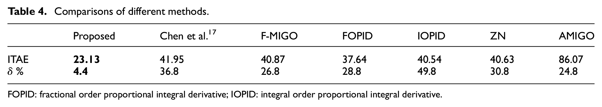
FOPID: fractional order proportional integral derivative; IOPID: integral order proportional integral derivative.
Conclusion
According to the requirements for the stability and robustness of the arbitrary integer order plus time delay system, this paper provides a method to construct the complete solution space of the parameters of the FOPI controller with specific stability-domain boundaries and frequency-domain specifications. The detailed designing procedures of the proposed FOPI controller are generalized with an example. By comparing the proposed FOPI controller with other controllers, the proposed one has the largest complete solution space and can be applied in arbitrary integer order plus time delay system. In the end, the comparisons of simulation and experimental results between the proposed method and some other methods are presented, which all shows the performance and benefit of the proposed FOPI controller.
Footnotes
Declaration of conflicting interests
The author(s) declared no potential conflicts of interest with respect to the research, authorship, and/or publication of this article.
Funding
The author(s) received no financial support for the research, authorship, and/or publication of this article.