
Abstract
The surface quality and accuracy of the geometry of the cylindrical rollers are important factors for bearing life. This paper presents effects of machining parameters on the surface roughness, topography and roundness of cylindrical rollers through the lapping and polishing experiments. And then the surface roughness of the cylindrical rollers is optimized. The results found that the surface roughness of rollers is significantly changed in lapping process with different abrasive particle sizes, while the surface roughness has slightly reduced in polishing process. It also indicated that the smoother surfaces with better roughness can be obtained after lapping and polishing process. In addition, the surface roughness of cylindrical rollers is rapidly reduced from Ra of 0.5 µm to Ra of 0.063 µm after the 3-h lapping process and Ra of 0.013 µm after the 1-h polishing process. The surface topography of rollers can be achieved by the smoother surface when loads are from 25 to 35 N in lapping process, and the loads are from 35 to 40 N in polishing process. Finally, the Taguchi method is applied to optimize the surface roughness in polishing process. The result found that the optimal surface roughness achieves 0.015 µm with respect to the time of 35 min and type of 4000# Al2O3.
Introduction
Cylindrical rollers are popular parts in mechanical equipment and machinery, electric motors, motorcycles and gearboxes. It is capable of supporting high radial and dynamic loads because the rolling rod and the rollers of bearings are in a direct contact. 1 Previously, the surfaces of cylindrical rollers were machined by turning and grinding.2,3 It is found that a large amount of time is required for the machining process to achieve a good surface quality. In addition, the machining conditions such as machine accuracy, grinding wheel speed and vibration greatly affect the efficiency of manufacturing process, which results in a very high machining cost.
In general, the double-side lapping and polishing techniques have been commonly used to process products such as silicon wafers, optical devices, rigid discs, ceramic balls and bearings. The surface quality and profile accuracy of the workpiece were significantly improved by using those machining techniques.4–6 In order to improve the surface quality of the cylindrical rollers, the influences of rotation of the roller, lapping plate, load, abrasive concentrate and abrasive size were studied.7–10 Experimental results showed that the roundness is achieved in the range of 0.91 μm, and the surface roughness in the range of 0.1 μm.11–13 Besides, electro-chemical mechanical polishing method (e-CMP) was applied to polish the crown cylindrical rollers. It revealed that the surface roughness and roundness of rollers are reduced less than 0.023 and 0.39 μm.14,15 Moreover, the surface quality of workpieces was extremely achieved the flat and smooth surface via using CMP technique.16–19 By using CMP method, the influents of chemical and the mechanical properties on the material removal process were studied.20,21 In addition, the contact process and machining trajectory of cylindrical rollers with lapping plate were simulated and analysed in previous studies.22,23 The chemical and mechanical polishing method was used to machining cylindrical rollers with double-side lapping plate. 24 The results found that the surface roughness and roundness are reduced from 76 to 16.6 nm and from 0.97 to 0.40 μm, respectively. Moreover, the lapping process was combined with ultrasonic techniques so as to improve the surface quality and processing efficiency of machined rollers.25,26 The process was supported by the pulse impact from the large number of abrasive particles. As a result, the surface roughness of crowned cylindrical rollers can reach Ra of 44.6 nm after 36 min of machining.
The purposes of this paper are to investigate effects of machining parameters on the surface roughness, topography and roundness of cylindrical rollers. The lapping and polishing experiments were carried on the precision lapping machine. And then the surface roughness of the cylindrical rollers is optimized. Many experiments were conducted to monitor and determine the surface roughness of cylindrical rollers under the differentially appropriate conditions. Based on the effects of experimental conditions such as the abrasive concentrate, abrasive size and machining load on the surface roughness of the cylindrical rollers, the Taguchi method is utilized to optimize the surface roughness.
Experiments setup
In the lapping and polishing process, the workpieces, conditioning rings and the carriers were driven and revolved by the friction of lower plate, as shown in Figure 1. Before processing, the cylindrical rollers were put in the square slots distributed radially on the circular carrier and between the upper and lower plates. Figure 2 depicts the square slots of circular carrier. And then the upper plate was controlled to move downwards and was pressed on the rollers by pneumatic pressure. At this time, the upper plate could freely rotate under the friction force which was generated during contact with the rollers. Based on the value of pneumatic pressure, the rollers were rolled and moved simultaneously in slot holes of carriers. The entire surfaces of the cylindrical rollers were machined by contacting between two plates and cylindrical rollers with abrasive slurry. Before lapping process, the cylindrical rollers were machined by CNC (Computer Numerical Control) turning. The initial surface roughness of the workpieces was 0.5 ± 0.02 μm. Subsequently, the cylindrical rollers were lapped on the double-side lapping machine to reach the required surface quality before entering the polishing process.
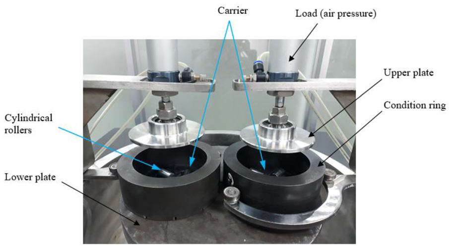
Experimental setup in the lapping processes.
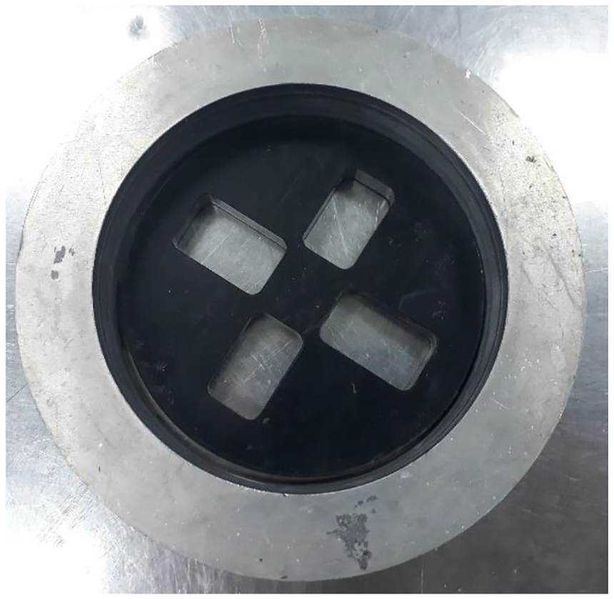
Circular carrier shape.
Experiment conditions for lapping and polishing
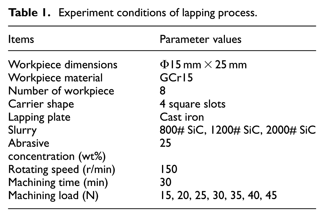
In the lapping process, the cylindrical rollers with 15 mm diameter and 25 mm length could be rotated and machined with SiC abrasive slurry. The slurry comprised SiC abrasive and water. The lower cast iron plate and the upper stainless steels plate were chosen for the experiment process. The lapping process parameters are given in Table 1.
Experiment conditions of lapping process.
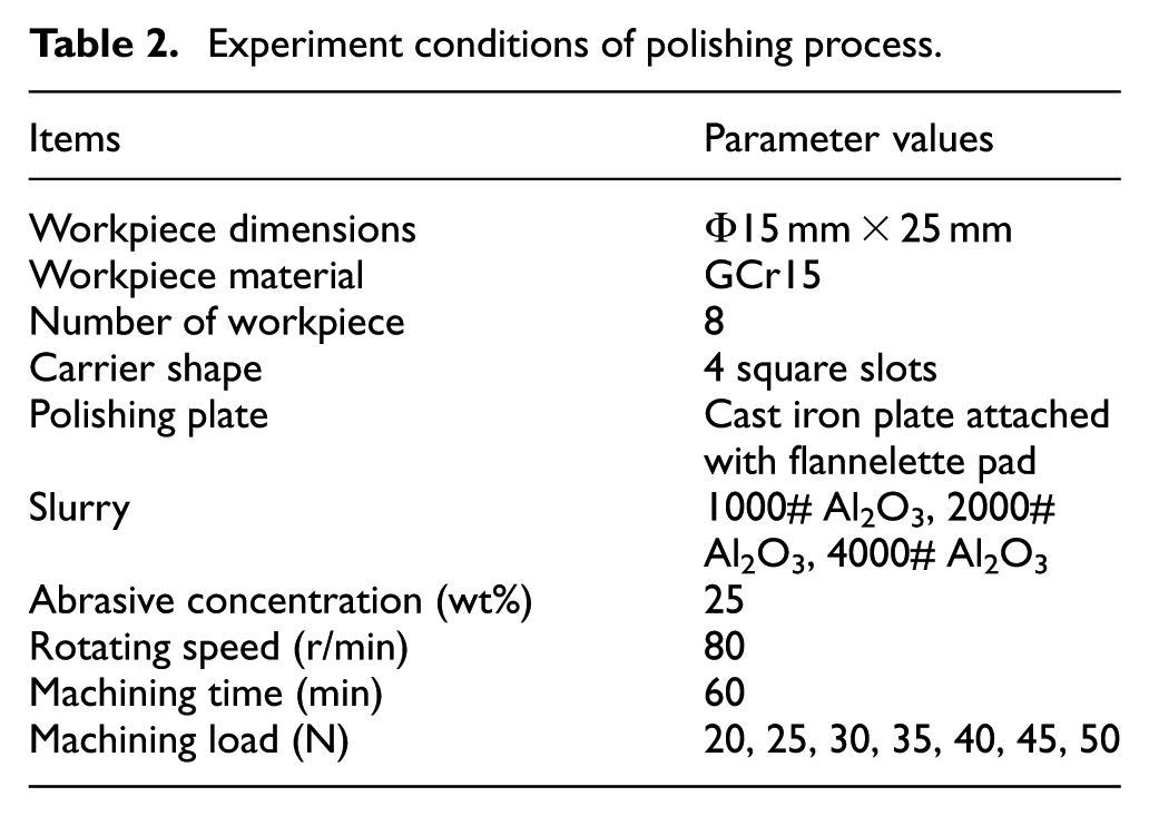
The polishing process was required so as to remove the micro-crack layers, which were remaining on the rollers after the lapping process. The cast iron plate was attached with flannelette pad and Al2O3 abrasive slurry which was used in the polishing process. The parameters of polishing process are given in Table 2.
Experiment conditions of polishing process.
Experimental results and discussion
Effect of abrasive size in lapping process
The lapping process was used to remove the machining trace and crack layers on the rollers after the turning process. During this process, particle size was an important specification of the abrasive in the machining process. In order to explore the effect of abrasive sizes, different types of 800# SiC, 1200# SiC and 2000# SiC abrasive were chosen for the experimentations. The speed of lapping plate was set at 150 r/min, the machining load of 30 N was chosen and the abrasive concentration of 25% was fixed.
The surface roughness and the roundness of cylindrical rollers after machining process were measured by SJ-310 roughness and Rondcom 41 °C, respectively. The surface roughness of workpiece after CNC turning was about 0.5 µm. In the first hour, the surface roughness of the workpiece was observed a sharp fall from 0.5 to 0.25 µm. During the following 3 h, the surface roughness of rollers had a little change, as presented in Figure 3. The surface roughness could reach Ra of 0.18 µm, Ra of 0.11 µm and Ra of 0.063 µm when the abrasive sizes were 800# SiC, 1200# SiC and 2000# SiC, respectively. These results indicated that the surface roughness of rollers is greatly influenced by the abrasive size. Based on the experiment results, the best surface roughness of the rollers is decreased from Ra of 0.5 µm to Ra of 0.063 µm after lapping process.
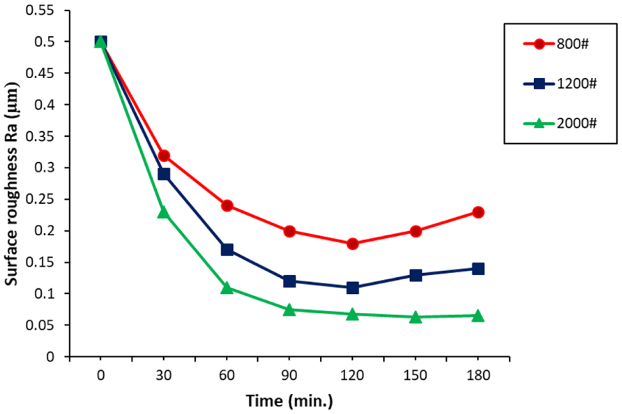
The influence of SiC abrasive size on surface roughness.
The surface topography of cylindrical rollers with different abrasive sizes in lapping process was investigated, as depicted in Figure 4. The surface topography of rollers was observed with an MDS metallurgical microscope.
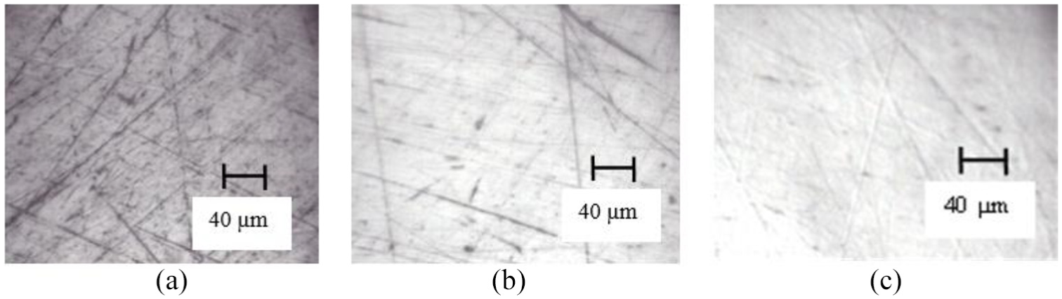
Relationship between abrasive size and micro-scratches in the lapping process: (a) 800#SiC, (b) 1200# SiC and (c) 2000#SiC.
Effect of load to surface roughness of rollers in lapping process
Different loads were experimentally studied, and the processing time per trial was approximately 1 h with the abrasive type and size being SiC, respectively. The speed of lapping plate and the abrasive concentration were chosen at 150 r/min and 25%, respectively. Different values of load were set up as 15, 20, 25, 30, 35, 40 and 45 N. The influences of load on the surface roughness were analysed, as given in Figure 5.
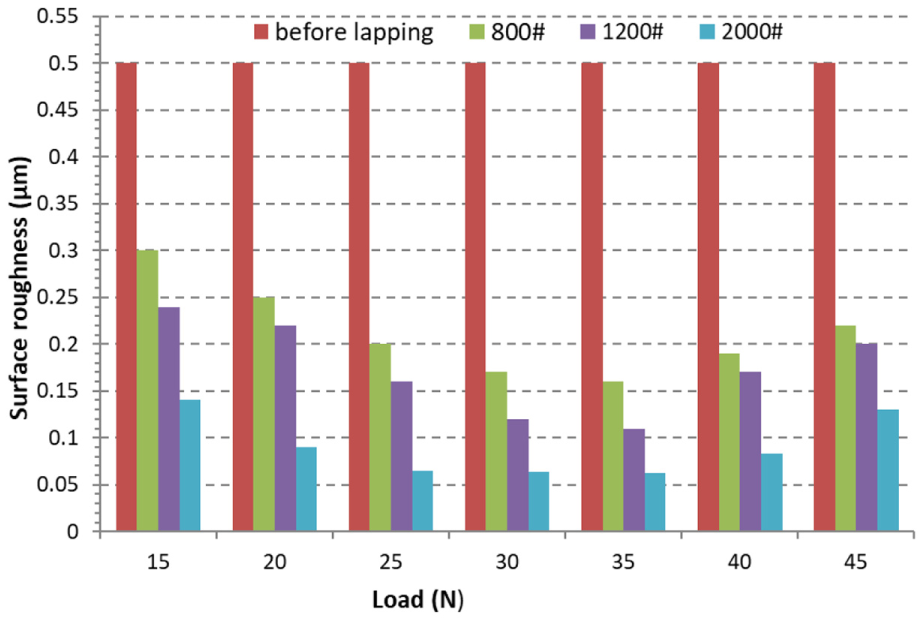
Relationship between the load values and the surface roughness.
From Figure 5, the results found that load is a factor affecting the surface roughness of the machined rollers. The surface roughness was significantly decreased when the loads were in the range from 25 to 35 N. However, if the load exceeded this range, the surface roughness was not significantly reduced or might even increase.
The surface topography of rollers with different loads in lapping process is presented in Figure 6. Experimental results showed that the micro-scratches of rollers decrease significantly when the loads are in the range from 25 to 35 N. When the load exceeded 35 N, the new scratches were generated on the surface of rollers. This could be explained that the contact friction force between the rollers and the lapping plate increases and exceeds the allowable limit of the machining process. In this case, the rollers were in the direct contact with the lapping plate without abrasive slurry between them. In addition, when the load increased beyond the permissible value, the roller did not seem to rotate but it would slip on the lapping plate. As a result, the surface quality of rollers bearing was not satisfied.
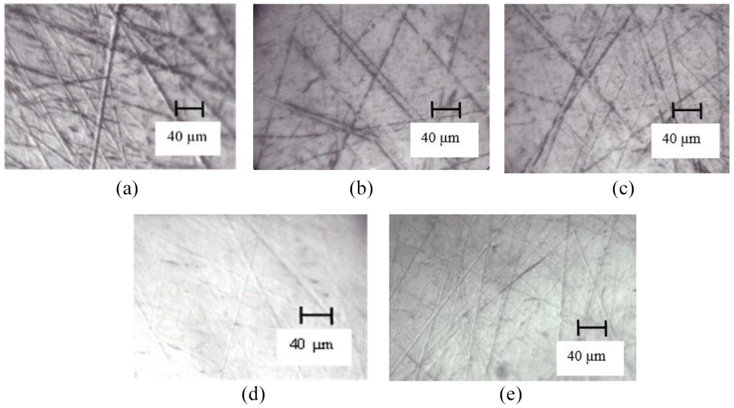
Relationship between the load values and the micro-scratches: (a) before lapping, (b) lapping with loads of 15 N, (c) lapping with loads of 20 N, (d) lapping with loads from 25 to 35 N and (e) lapping with loads greater than 35 N.
Effect of load to roundness of rollers in lapping process
The cylindrical rollers were lapped with SiC abrasive slurry under different conditions of loads. The roundness and circular profile of the cylindrical rollers were carried out and analysed after lapping process. The relationship between the values of load and the roundness is displayed in Figure 7.
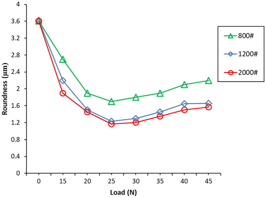
Relationship between the load values and the roundness in lapping process.
During the lapping process, using the 800# SiC and the abrasive concentration of 25%, the average roundness of workpieces was decreased from 3.62 to 2.24 μm. When the 1200# SiC and 2000# SiC abrasive slurry were utilized, the roundness had a similar behaviour in the same values of load. The average roundness decreased from 3.62 to 1.6 μm when using the 2000# SiC. The roundness of rollers reached a minimum value when the loads were in the range from 25 to 30 N. However, the load exceeded the range, the roundness was increased. The circular profile of cylindrical rollers is demonstrated in Figure 8. Pictures of workpiece surface before and after lapping are shown in Figure 9.
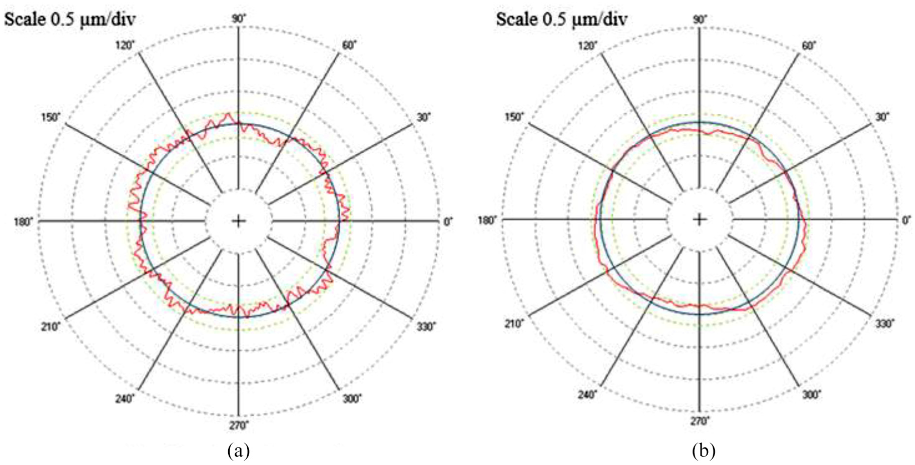
Circular profiles of cylindrical rollers before and after lapping process: (a) before lapping (3.62 μm) and (b) after lapping with 2000# SiC slurry (1.6 μm).
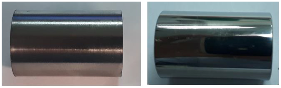
Surface roughness of the cylindrical rollers surface: (a) before lapping and (b) after lapping.
Effect of abrasive size in polishing process
After the lapping process, the polishing was required to remove micro-crack layer and trace. The influential factors, including abrasive size and load on the surface roughness, were investigated. In order to achieve a higher surface quality, both the upper and lower plates were covered with flannelette polishing pad. The experiments for the polishing processes were setup, as shown in Figure 10.
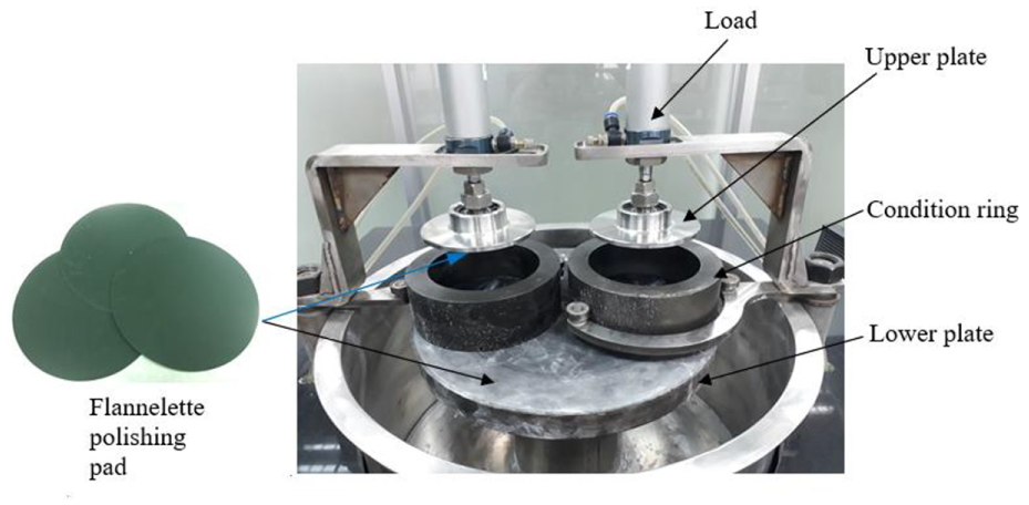
Experimental setup in the polishing processes with flannelette polishing pad.
Next, an experiment had been investigated under appropriate conditions, including the speed of polishing plate of 80 r/min, abrasive concentration of 25% and machining load 35 N. In addition, the upper and lower plates were covered with flannelette polishing pad to reduce the criss-crossing and tiny scratches. The abrasive grain sizes of 1000# Al2O3, 2000# Al2O3 and 4000# Al2O3 were chosen for the experiments. The influence of Al2O3 abrasive sizes on surface roughness of rollers in polishing process is given in Figure 11.
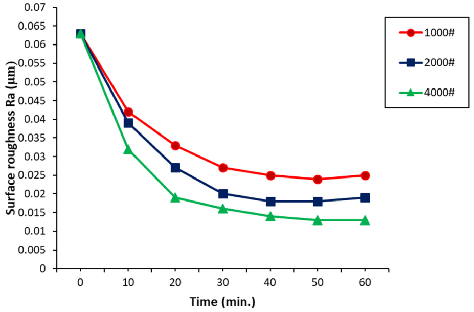
The influence of Al2O3 abrasive sizes on surface roughness.
The results of Figure 11 showed that the quality of machined surface can be increased when the abrasive size decreases. In 25 min, the surface roughness of the workpiece observed a sharp fall from Ra of 0.063 to Ra of 0.013 µm with abrasive size of 4000# Al2O3. During the following 35 min, the surface roughness could reach Ra of 0.025, 0.019 and 0.013 µm when the abrasive sizes were 1000# Al2O3, 2000# Al2O3 and 4000# Al2O3, respectively. The surface topography of cylindrical rollers with different abrasive sizes in polishing process was presented in Figure 12.
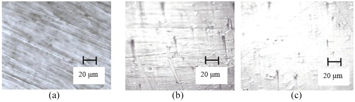
Relationship between the abrasive size and the micro-scratches in polishing process: (a) 1000# Al2O3, (b) 2000# Al2O3 and (c) 4000# Al2O3.
Effect of load in polishing process
In this experiment, the different load values were set at 20, 25, 30, 35, 40, 45 and 50 N. The processing time per trial was 1 h with the abrasive type and size being Al2O3 and 4000#, respectively. The speed of lapping plate and the abrasive concentration were at 80 r/min and 25%, respectively. The relationship between the load values and the surface roughness is illustrated in Figure 13.
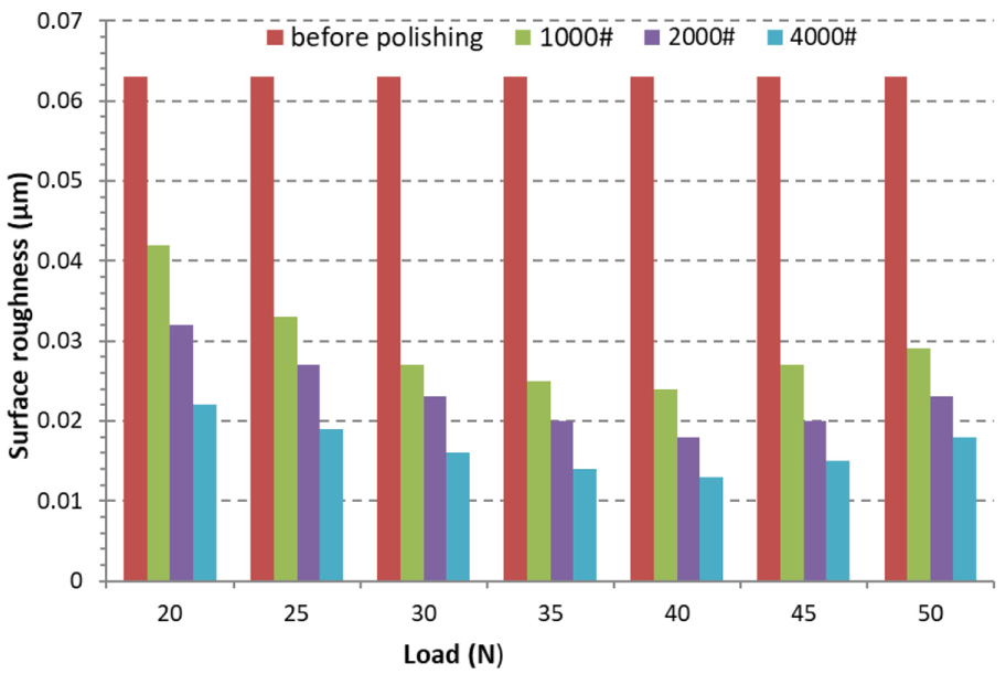
Relationship between the load values and the surface roughness.
The results of Figure 13 found that the load is an important parameter affecting the quality of the machined surface. The surface roughness of rollers could significantly decrease when the loads were in the range from 35 to 40 N. However, if the load exceeded the range, the surface roughness did not significantly reduce. The surface roughness of rollers achieved the best value Ra of 0.013 μm when the applied force was 40 N after 60 min of polishing. The results showed that the polishing process with double plates attached with flannelette polishing pad can improve the surface quality of the rollers.
The surface topography of roller with different loads in polishing process is shown in Figure 14. Based on the experiment results, the micro-scratches of rollers would significantly decrease when the loads were in the range from 35 to 40 N. When the load exceeded 40 N, the new scratches were generated on the surface of the rollers.
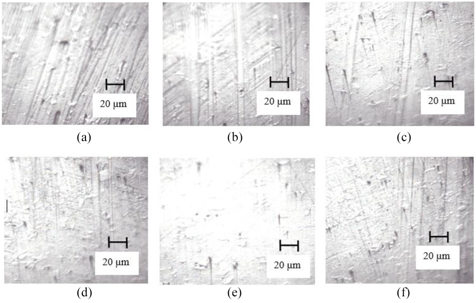
Relationship between the load values and the micro-scratches: (a) before polishing, (b) polishing with loads of 20 N, (c) polishing with loads of 25 N, (d) polishing with loads of 30 N, (e) polishing with loads from 35 to 40 N and (f) polishing with loads greater than 40 N.
Effect of load to roundness of rollers in polishing process
In the polishing process, the cylindrical rollers were polished with Al2O3 abrasive slurry under different conditions of loads. The roundness and circular profile of the cylindrical roller after polishing process were discussed and evaluated. Figure 15 illustrates the correlation between the roundness of the cylindrical rollers with different loads.
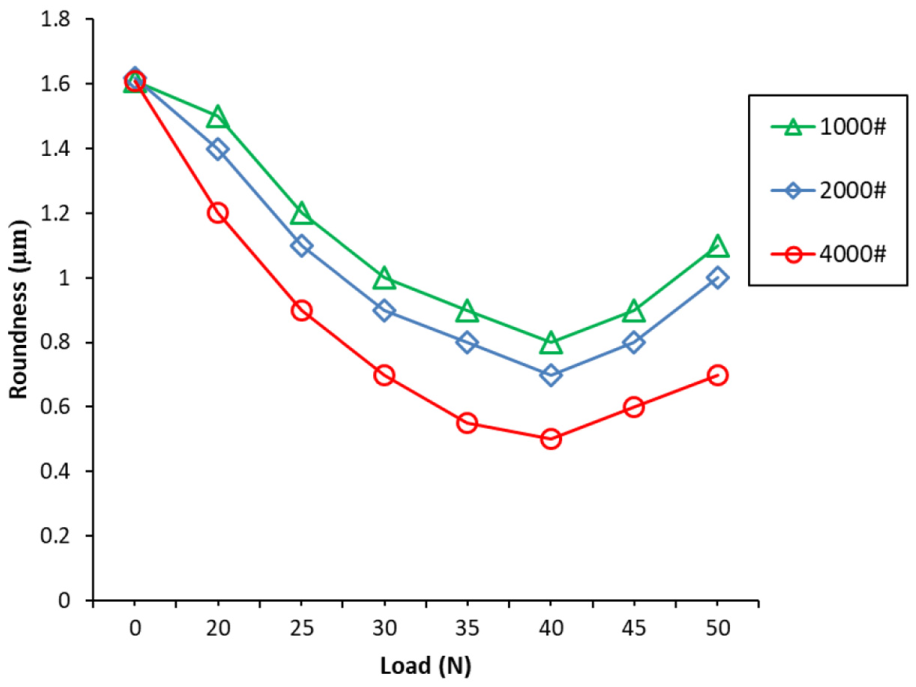
Relationship between the load values and the roundness in polishing process.
During the polishing process, by using the 1000# Al2O3 and the abrasive concentration of 25%, the average roundness of workpieces was decreased from 1.62 to 0.93 μm. Meanwhile, using the 2000# Al2O3 and 4000# Al2O3 abrasive slurry, the roundness was also decreased from 1.62 μm to 0.8 μm and 0.51 μm. As shown in Figure 15, the roundness of roller reaches the minimum value when using the 4000# Al2O3 abrasive slurry and 40 N of load.
This roundness could be increased when the load exceeded 40 N. The circular profile of cylindrical rollers is shown in Figure 16. The pictures of workpiece’s surface before and after polishing are given in Figure 17.
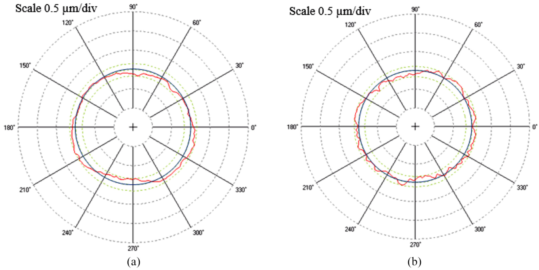
Circular profiles of cylindrical rollers before and after polishing: (a) before polishing (1.62 μm) and (b) after polishing with 4000# Al2O3 abrasive (0.51 μm).
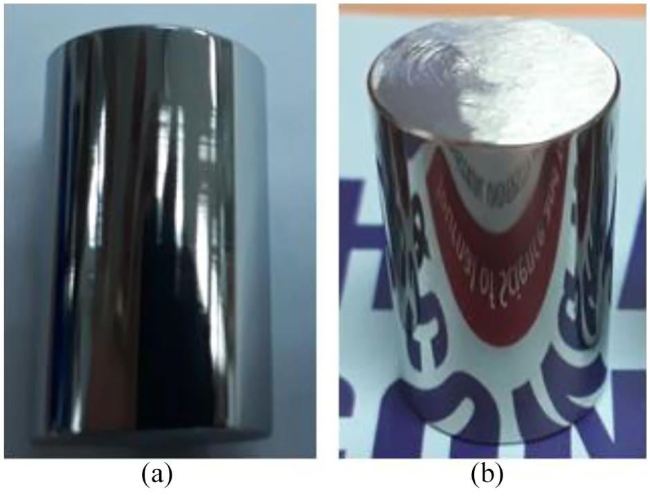
Surface roughness of the cylindrical rollers surface: (a) before polishing and (b) after polishing.
Optimization for surface roughness in polishing process
Polishing phase is an important step to improve the machining quality through decreasing the surface roughness. In order to optimize the surface roughness, the experimental optimization method was preferred. In this investigation, the Taguchi method27–32 was adopted so as to optimize the surface roughness.
The Taguchi method is a robust design in which parameter design is commonly used to determine suitable levels of controllable parameters. The parameter design is used because the Taguchi method helps to reduce the number of experiments instead of using full factorial design. Hence, it can improve the machining quality and decrease the manufacturing cost so as to achieve a desired target.
This method is evaluated by using the signal-to-noise (S/N) ratio value of the quality response. The Taguchi robust parameter design can categorize into three cases: (a) smaller-the-better, (b) larger-the-better and (c) nominal-the-best. In this article, the surface roughness was desired to gain a minimum value; thus, the-smaller-the-better response was utilized and defined as follows

where η is the S/N ratio, n is the number of experiment and Yi is the surface roughness data at the experiment ith.
As mentioned above, the load and abrasive size were two factors that affect surface roughness of cylindrical rollers. However, the load value could be changed by the concentration of slurry during the machining process. When the load value was increased, the vibration of the device could be aggravated, which might be attributed to the increase in the contact area and the increase in the frictional force between the cylindrical surface of the rollers and the nodular cast iron plates. In addition, the accuracy of experimental equipment also affected the load in the machining process while the machining conditions had a little effect on abrasive size. Therefore, the load was ignored in the optimization process. Finally, the time and abrasive size were selected as controllable parameters, called as design variables.
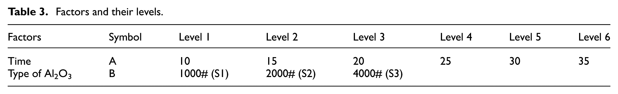
In this study, the time and types of Al2O3 were chosen in two main factors affecting the surface roughness. The time was divided into six levels and the types of Al2O3 were separated into three levels. Considering the time, levels 1, 2, 3, 4, 5 and 6 were corresponding to 10, 15, 20, 25, 30 and 35 min. Meanwhile, the types of Al2O3 included level 1 with respect to 1000# (S1), level 2 with respect to 2000# (S2) and level 3 with respect to 4000# (S3). According to the Taguchi method, the L18 orthogonal array was used to build the experiment matrix.
As mentioned above, there two key factors included the time and type of Al2O3, which were considered as key controllable parameters affecting the quality of surface roughness. The time was labelled as A, and the type of Al2O3 was labelled as B. Factor A was divided into six levels and factor B was divided into three levels. The factors A, B and their levels are given in Table 3. Using L18 orthogonal array, the 18 experiments were conducted, and the results of surface roughness were recorded. And then the S/N ratio values of surface roughness for each experiment were calculated using Equation (1), as given in Table 4. The average value of S/N ratios for factors A and B was computed separately, as shown in Table 5. By using the data in Tables 5, the effect plot of factors A and B at each level versus S/N ratio values was illustrated, as depicted in Figure 18. According to the Taguchi method, a better quality characteristic is with respect to a larger value S/N ratio. Therefore, based on Table 5 and Figure 18, the result found that the optimal surface roughness is about 0.015 µm. The optimal factors are determined at the time of 35 min (level 6) and type of 4000# Al2O3 (level 3). It means that the optimal parameters are found at A6B3, as seen in Figure 18.
Factors and their levels.
S/N ratio results of surface roughness.
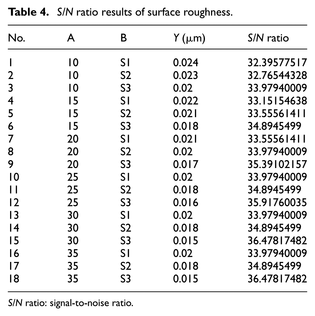
S/N ratio: signal-to-noise ratio.
Average value for S/N ratio at each level.
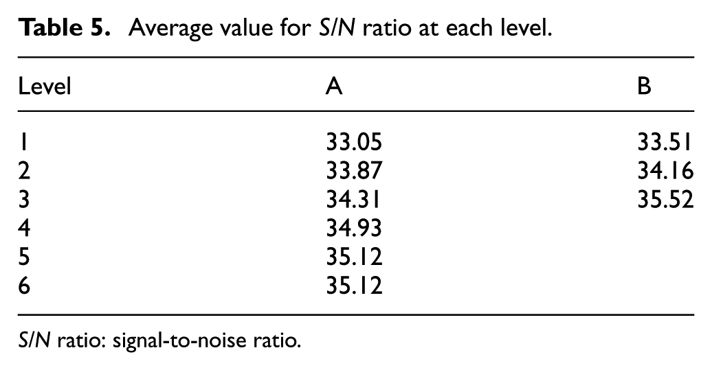
S/N ratio: signal-to-noise ratio.
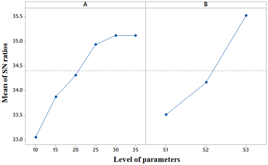
Main effects plot for S/N ratios.
Conclusion
In this study, many experiments have been presented to reveal the influences of abrasive size and machining load on the surface roughness and roundness of rollers in lapping and polishing process. From the experiment results, the conclusions can be summarized as follows:
Abrasive sizes have the effects on the surface roughness. The surface roughness of rollers has changed significantly in lapping process. The surface roughness can reach Ra of 0.063 µm when the abrasive size is 2000# SiC in lapping process. However, the surface roughness has reduced slightly in polishing process. Surface roughness of rollers with Ra of 0.063 µm was polished down to Ra of 0.013 µm after 1 h of processing with abrasive size of 4000# Al2O3.
During polishing process using the 1000# Al2O3 and the abrasive concentration of 25%, the average roundness of workpieces has decreased from 1.62 to 0.93 μm. When using the 2000# and 4000# Al2O3 abrasive slurry, the roundness was also decreased from 1.62 μm to 0.8 μm and 0.51 μm. The experimental result found that the roundness of roller reaches the minimum value when using the 4000# Al2O3 abrasive slurry and 40 N of load.
Taguchi method was used to optimize the surface roughness. The parameter of time and abrasive size are selected as optimization parameters. The result revealed that the optimal surface roughness is about 0.015 µm corresponding to the time of 35 min and type of 4000# Al2O3.
Footnotes
Declaration of conflicting interests
The author(s) declared no potential conflicts of interest with respect to the research, authorship and/or publication of this article.
Funding
The author(s) disclosed receipt of the following financial support for the research, authorship and/or publication of this article: This research is funded by Vietnam National Foundation for Science and Technology Development (NAFOSTED) under grant number 107.03-2018.11