
Abstract
Residual stresses are induced in the material during manufacturing operations, which considerably affect the fatigue performance and the lifespan of a mechanical work piece. The nature, magnitude, and distribution of residual stresses decide their beneficial or detrimental effects. Past research efforts concluded that mechanical process parameters influence residual stress nature, distribution, and the magnitude. Nevertheless, how residual stress generation depends on the process parameters, is not well investigated especially in the case of a drilling operation. In fact, the residual stress field is required to be regulated near drilled holes to improve the fatigue strength of structural joints, especially in the aircraft industry. Accordingly, this work attempts to estimate the drilling-induced micro-residual stress distribution near the drilled hole. In addition, the effect of drilling speed on residual stress distribution has also been studied. A nanoindentation technique is used to follow-up precise distribution of micro-residual stresses near the holes drilled at three different drilling speeds of 700, 900, and 1100 r/min. The outcomes indicate the presence of compressive residual stresses near the hole. In addition, an increase in residual stress level is noticed with an increase in the drilling speed up to 900 r/min. A uniform distribution of residual stresses is observed near the hole when drilled at a higher drilling speed of 1100 r/min. These findings may be useful in planning an improved drilling operation to produce beneficial residual stress distribution. This may ultimately improve the fatigue strength and the service life of mechanical components or structures with drilled holes.
Introduction
Residual stresses are typically locked-in-stresses which occur against any external load or deformation and remain within the material even though the load is removed.1,2 Totten 2 extensively reviewed studies about the residual stresses induced during various manufacturing processes such as metal forming, machining, welding, forging, and heat treatment. Wang and Gong 3 highlighted that most of the metal-forming operations such as drawing, rolling, and extrusion develop residual stresses. Along the same line, the presence of residual stress is noticed in the machined surface by Liu and Barash, 4 whereas Pyzalla and Reimers 5 indicated that cold and hot working operations also impart residual stresses at the surface of worked objects. Several experimental investigations have also reported that welding and heat-treatment operations induce residual stresses in the material as a result of change in temperature or thermal energy.6–8 It has been noticed that residual stresses adversely affect structural strength, fatigue behavior, and performance and life span of a mechanical work piece. 9 For example, Barsoum and Barsoum 10 observed that residual stresses may affect the crack-propagation behavior, whereas Totten and Howes 11 elucidated that residual stresses can be a reason for the change in shape of manufactured object. This may ultimately lead to premature failure of a mechanical part. Totten 2 indicated that metal removal and forming processes introduce localized plastic deformations within the material. These deformations may encourage crack initiation and propagation and hence promote the fatigue failure of mechanical components. Localized deformations can be accessed from the measurement of residual stresses typically present at a scale of nearly 100 μm or less. Jang 12 reported that these localized deformations can be referred as micro-scale residual stresses. Thus, a comprehensive knowledge of nature, magnitude, and distribution of micro-scale residual stresses, originating from manufacturing process, is essential to improve the performance and the service life of a mechanical component.
Drilling is a frequently performed manufacturing operation to create holes for bolted, riveted, and pinned joints. In the aerospace industry, mechanical joints are widely used to fasten structures and components. In such case, holes become the prime requirement. These holes act as stress-localization sites under cyclic loading. As a result, these sites are more susceptible to crack initiation and propagation. This may lead to fatigue failure of components or the whole structure. Such failures account nearly 50%–90% of fractures in aging aircrafts. 13 Yongshou et al. 14 carried out experimental and numerical investigations to assess the fatigue performance of fastener holes. They observed that the presence of local residual stress near the hole-edge is favorable for crack initiation and propagation. Vuherer et al. 15 also investigated the influence of local plastic deformations and micro-scale residual stresses on crack nucleation and propagation using Vickers-pyramid indentation test. This work well explained that micro-scale tensile residual stresses assist in crack propagation. Liu et al. 13 indicated that dislocations and surface scratch also contribute in crack initiation and growth; nevertheless, the role of permanent deformation is considered more imperative. Urriolagoitia-Sosa et al. 16 carried out both experimental and numerical investigations simultaneously to understand the crack initiation and propagation behavior in the presence of an applied compressive residual stress field. The outcomes indicated that crack propagation will require sufficient energy to overcome this applied stress field. Minguez and Vogwell 17 have shown that tensile stresses near the hole could be unfavorable for fatigue life of the component; whereas, the presence of compressive stresses improves the same. Thus, the nature of residual stress near the hole (i.e. tensile or compressive) decides its beneficial or detrimental effects.
A series of experimental studies by Chakherlou and Vogwell18,19 proposed a cold expansion method to impart uniform compressive residual stress field near the fastener hole. In this method, an oversized pin is forced through the drilled hole to produce compressive tangential stresses around the hole so that the fatigue resistance at such locations can be improved. Chakherlou and Vogwell 18 however suggested that cold expansion method may also introduce tensile tangential stresses near the hole-edge which are typically undesirable. Rans et al. 20 have reported that rivet installation squeeze force introduces a compressive residual stress field near the holes which substantially reduces crack initiation and propagation. In addition, Zhao et al. 21 mentioned that residual stress magnitude and distribution can be regulated by changing the expansion intensity. Ren et al. 22 have also demonstrated that laser shock drilling significantly impedes the crack initiation near the hole-edge, as it imparts compressive residual stresses. Liu 23 elucidated the mechanics of crack growth around a hole in the presence of residual stress field. It is noticed that residual stress distribution considerably influences crack propagation and its direction under cyclic loading.
Liu et al. 24 carried out experimental and numerical investigations to understand the fatigue performance of fastener holes. This study concluded that the nature of local plastic deformation and distribution of residual stresses decide the speed of crack propagation around the hole. In fact, crack initiates near the hole-edge and then rapidly propagates in the transverse direction than the bore direction. Moreover, pre-existing local or micro-scale residual stresses can be more destructive, as it assists in crack initiation at a level lower than the fatigue limit. 15 These findings from the literature suggest that local residual stress magnitude, nature, and distribution considerably affect crack nucleation and growth behavior and hence the fatigue resistance of fastener holes. It is, therefore, essential to control or improve the residual stress field imparted by drilling operation near the hole.
Flaman 25 investigated the effect of drilling process parameters on residual stress distribution to improve the drill-hole techniques of residual stress measurement. They have suggested that high-speed drilling minimizes residual stress development. Nobre and Outeiro 26 performed experimental and numerical investigations to estimate the high-speed drilling-induced residual stresses. This work also concluded that drilling process parameters considerably affect the nature and the distribution of residual stress. Several other studies have also suggested that optimal process parameter setting may generate favorable residual stress distribution in welding, forming, and material removal processes such as machining.27,28 For example, Capello 29 identified an analytical relationship between residual stresses and turning process parameters, for example, feed rate. This work explained that feed rate and tool-nose radius influence residual stress magnitude and distribution. In addition, Coto et al. 30 also analyzed the distribution of residual stresses developed during turning of AISI 4340 steel and concluded that turning parameters govern the mechanism of residual stress development. Similarly, Neugebauer et al. 31 have shown that residual stress magnitude decreases with an increase in cutting speed during the machining operation. These aforementioned studies encourage that optimal process parameters may also be selected during drilling operations to regulate residual stress field near the holes. However, the relationship between drilling parameters, and residual stress distribution is not well established. Based on the above findings, this study attempts to investigate the drilling-induced micro-residual stresses near the holes. This study also investigates the effect of a drilling parameter specifically speed on residual stress magnitude and distribution. In our approach, a mild-steel plate is drilled in a close range of recommended drilling speed provided in Machinery’s Handbook Guide 32 and drilling charts, and residual stress distribution at micro-scale has been estimated.
Rossini et al. 33 summarized residual stress measurement techniques, their advantages, and limitations. It can be noticed from the literature that semi-destructive methods of residual stress measurement such as hole and deep-hole drilling methods have spatial resolution ranging from 10 to 100 mm; whereas, non-destructive methods specifically ultrasonic and Barkhausen noise methods have spatial resolution in a range of 1–10 mm (refer Figure 14 in Rossini et al. 33 ). Although these are fast, easy, and low-cost methods of residual stress estimation, they are suitable to evaluate residual stresses at a macro scale. In contrast, other non-destructive methods such as X-ray diffraction, Neutron diffraction, and synchrotron methods have better spatial resolution ranging from 1 mm to 1 μm. These methods have the ability to evaluate both macro- and micro-residual stresses. Nevertheless, these methods have certain limitations. For example, X-ray diffraction measurement requires small components and provides the information about total residual stresses at global scale. In addition, it is difficult to measure residual stresses locally or site-specifically using aforementioned non-destructive techniques, which is although required to obtain the stress-distribution plots. 34 Instrumented indentation also has the ability to measure short-range (micro and nano) and long-range (macro) residual stresses locally or site-specifically using macro-, micro-, and nanoindentation. 35 Thus, a general principle may also be opted to obtain residual stresses at different length scales. This instrumented indentation technique of residual stress measurement also provides flexibility to design and develop non-destructive testing tools which may be useful in improving the material processing and manufacturing operations. Vogt et al. 36 recently concluded nanoindentation is advantageous over the hole-drilling method in extracting the near-surface and high-resolution spatial distribution of residual stresses. These advantages encouraged this study to employ nanoindentation technique to estimate the residual stress distribution near the hole. The outcomes of this study provide the map of micro-scale residual stress distribution near the drilled hole within a precise zone of 2000 μm from the hole-edge. This study contributes in elucidation of residual stress distribution induced during a drilling operation. These findings can be useful in identification of suitable methods or optimal process parameters to impart uniform, beneficial, and permissible residual stress distribution near the holes. This may ultimately be useful for the improvement of the fatigue strength of fastener holes and thus the aircraft structures.
Material and methods
Sample preparation
Four mild-steel plates of identical dimensions (50 mm × 50 mm × 6 mm) have been separated from a plate of dimension (250 mm × 100 mm × 6 mm). A 10-mm hole has been drilled at the center of all the plates. Holes have been created using a high-speed steel (HSS) drill bit at three different drilling speeds of 700, 900, and 1100 r/min, respectively, at room temperature. These speeds are selected based on Machinery’s Handbook Guide and drilling charts, 35 which recommend drilling speeds in a range of 747–887 r/min for mild steel. Accordingly, first two speeds 700 and 900 r/min are selected, as these are the lowest and the highest recommended speed, respectively, in this range. A relatively higher speed (1100 r/min) beyond the recommended speed limit is also selected to understand the effect of increased speed beyond optimal limit on residual stress distribution. It has been assumed that drilling process induces residual stress in all three plates; whereas, the fourth plate without drilling has been considered as stress-free specimen and used as a reference. All the specimens were polished at low speed with EcoMet 250® (Buhler, Switzerland) before the operation to ensure the residual stress-free surface or to maintain the minimal stress level at all the surfaces. Specimens drilled at the speed of 700, 900, and 1100 r/min are shown in Figure 1(a)–(c), respectively. Small specimens of size (25 mm × 25 mm) are taken out from the side-wall of the hole. Small irregularities and unevenness present near the hole are removed with EcoMet 250 (Buhler, Switzerland) at low speed to turn worn and uneven surface into a reasonably smooth surface to minimize error in nanoindentation measurements. In this study, we have selected a region of interest or zone lying under a distance of 2000 μm from the hole’s edge (Figure 1). Residual stress has been mapped in this zone. The zone has been further divided into six sub-zones at radial distances of 250, 500, 750, 1000, 1250, and 2000 μm. Corresponding circles have been drawn from hole’s center at a radius of R1, R2, R3, R4, R5, and R6 as shown in Figure 2. Each circle’s circumference has been divided into qui-angle sectors with 12 radial lines, each 30° apart from the neighboring lines and passing through the center of the hole. Radial lines intersect circles at points mentioned as ji, ki, li, mi, ni, and oi (i = 1 to 7) in the anti-clockwise direction and ji′, ki′, li′, mi′, ni′, and oi′ in clockwise directions. Nanoindentation has been performed at these points to map residual stress distribution in the region of interest near the hole.
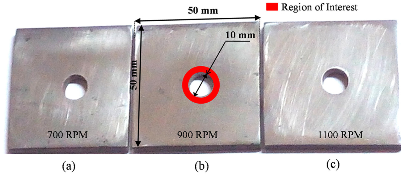
Mild-steel samples with a 10-mm hole drilled at 700, 900, and 1100 r/min.
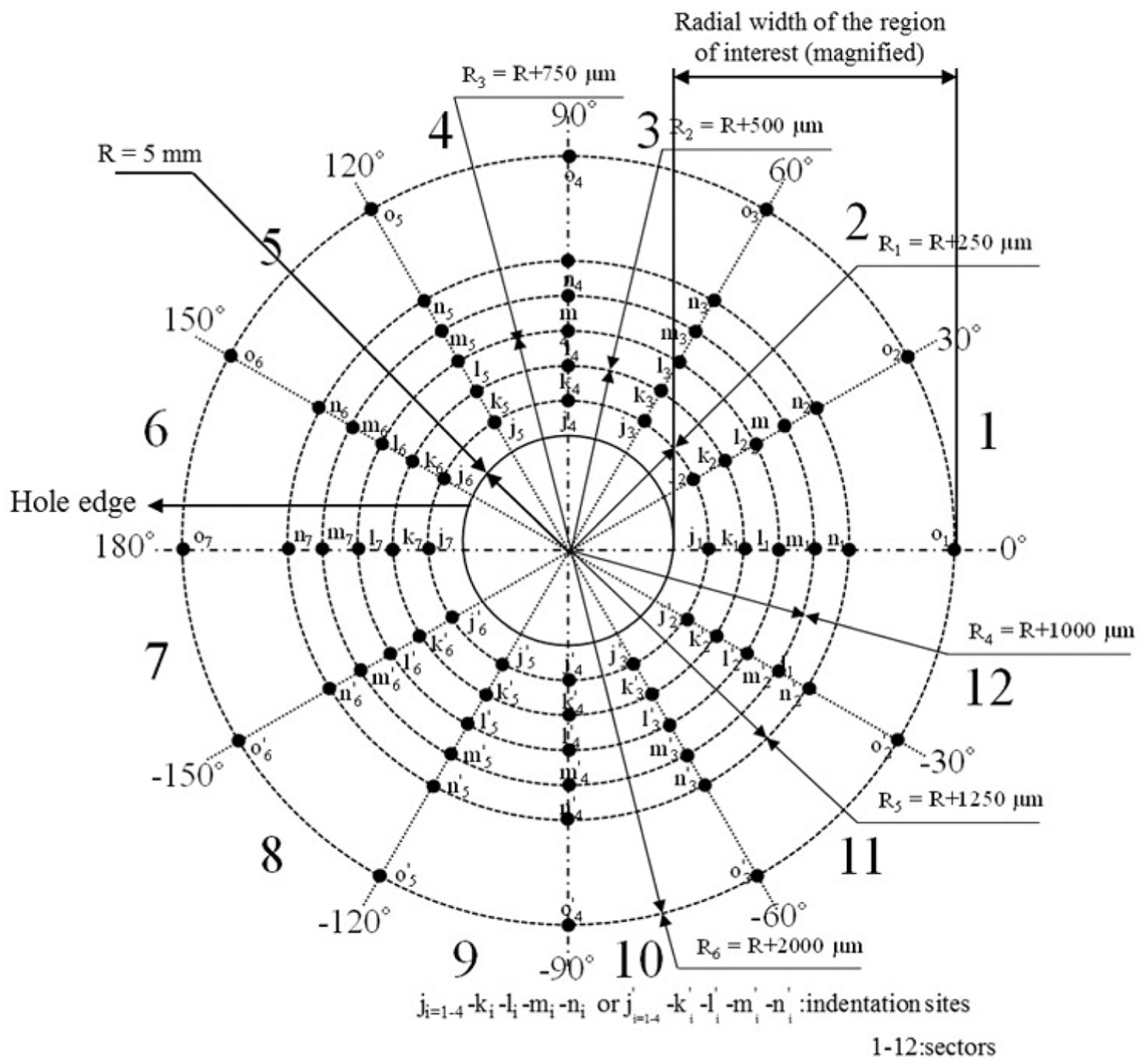
Indentation scheme used to map residual stress distribution near the hole is shown.
Residual stress estimation
In recent years, nanoindentation has been extended from the estimation of mechanical properties such as Young’s modulus and hardness to residual stress measurement. This technique also provides information on the nature of residual stresses (tensile and compressive) since the material with compressive or tensile residual stresses correspondingly require lesser or larger forces to achieve a constant penetration depth in comparison to a stress-free material. A shift in load–depth (P-h) curve from the reference material’s P-h curve indicates the presence of residual stresses. 37 Furthermore, Zhu et al. 38 investigated the pile-up behavior during nanoindentation and suggested that the shape of material pile-up near contact circle of penetration presents the information on the level and the nature of residual stresses. To incorporate all these attributes, this study has used TriboIndenter®-TI 950 (Hysitron Corporation, USA) with a Berkovich diamond indenter to perform nanoindentation. Tip calibration has been performed using standard quartz samples. The material has been penetrated at a constant depth of 250 nm in depth-control mode, and load–depth (P-h) curves have been acquired. Mechanical properties such as hardness, reduced Young’s modulus, and contact area have been obtained from nanoindentation using equations reported by Oliver and Pharr. 39 These equations and mechanical properties have been further incorporated in the model by Suresh and Giannakopoulos 34 to estimate the residual stresses.
Theoretical model
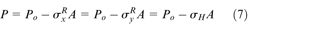
This work uses the model of Suresh and Giannakopoulos 34 to estimate residual stresses. The model estimates residual stresses based on the difference in indentation load–depth curves of stressed and reference samples. The model assumes that residual stresses are uniform over the depth of the influence of the indenter. Kick’s and Meyer’s law are typically used to relate indentation load (P) to contact depth (h). Accordingly, load and depth for substrates without and with residual stress have been related as follows


where Po and P are indentation loads to achieve corresponding penetration depths of ho and h in the substrates without and with residual stresses, respectively.


where
The model assumes that a biaxial state of tensile or compressive residual stresses
or

Substituting values of

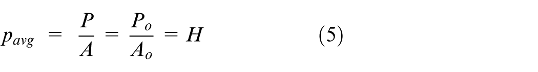
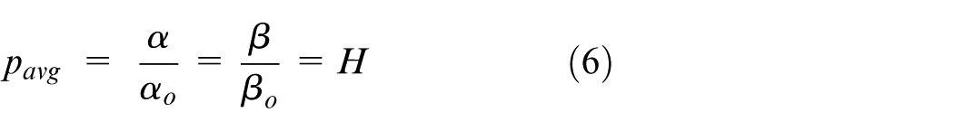
or
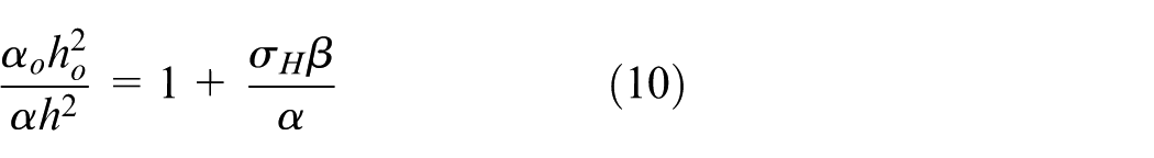
Using equations (3)–(5), equation (10) is further modified as
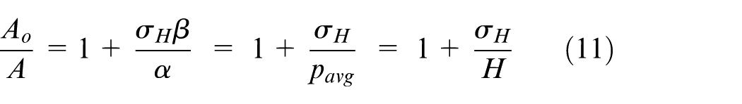
Thus, tensile residual stress can be expressed as a function of hardness and contact areas (
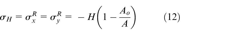
Similarly, compressive residual stress can be calculated as
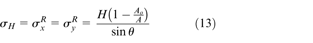
where
Results
Load–depth (P-h) curves obtained from nanoindentation near the hole (stressed) and a stress-free or reference specimens have been compared (Figure 3(a)). Evidently, the indentation load required to achieve a penetration depth of 250 nm in drilled/stressed material is greater as compared to the stress-free material. It indicates that residual stresses are present near the hole and may be compressive in nature. Material pile-up near the indented surface confirms the presence of compressive residual stresses which also aligns with the findings of Zhu et al. 38 This material pile-up has been noticed in all the samples drilled at 700, 900, and 1100 r/min (Figure 3(b)–(d)). It has also been noticed that pile-up amount varies considerably with the change in drilling speed. Thus, drilling speed may have influenced the magnitude and the distribution of residual stresses near the hole.
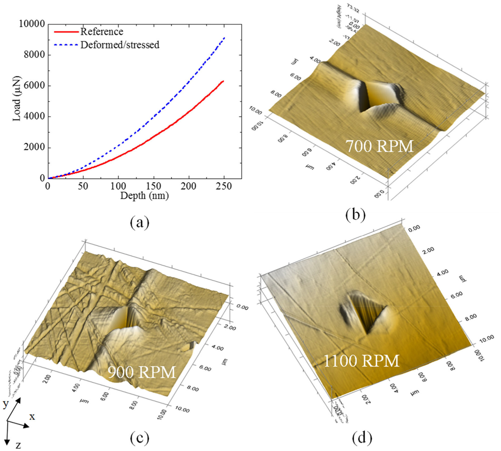
In situ images showing material pile-up at an indented surface near the holes drilled at a speed of: (a) 700, (b) 900, and (c) 1100 r/min, respectively, and (d) comparison of load–depth (P-h) curves obtained from indentation of unstressed and stressed samples.
Figure 4 show residual stress distribution within a radial distance of 2000 μm from the edge of holes drilled at 700, 900, and 1100 r/min. This distribution is obtained by averaging the values of residual stresses measured at circumferential sites located along a given radial distance. It can be noticed that maximum residual stress occurs near the edge of the hole drilled at 700 r/min. The magnitude of residual stress also decreases with increase in radial distance from the hole’s edge (Figure 4(a)). In contrast, distribution of residual stress near the hole drilled at 900 r/min is entirely opposite to that has been observed at 700 r/min which implies that the stress magnitude increases with increase in radial distance from the edge of the hole (Figure 4(b)). A relatively high-speed drilling at 1100 r/min resulted in a uniform distribution of residual stresses around the hole; nevertheless, distributions of residual stresses were non-uniform around the holes drilled at 700 and 900 r/min (Figure 4(c)). Interestingly, peak residual stress has also been noticed away from the hole-edge and specifically at a radial distance of R6, that is, 2000 μm for the hole drilled at 1100 r/min. This effect is quite similar to that has been observed at 900 r/min.
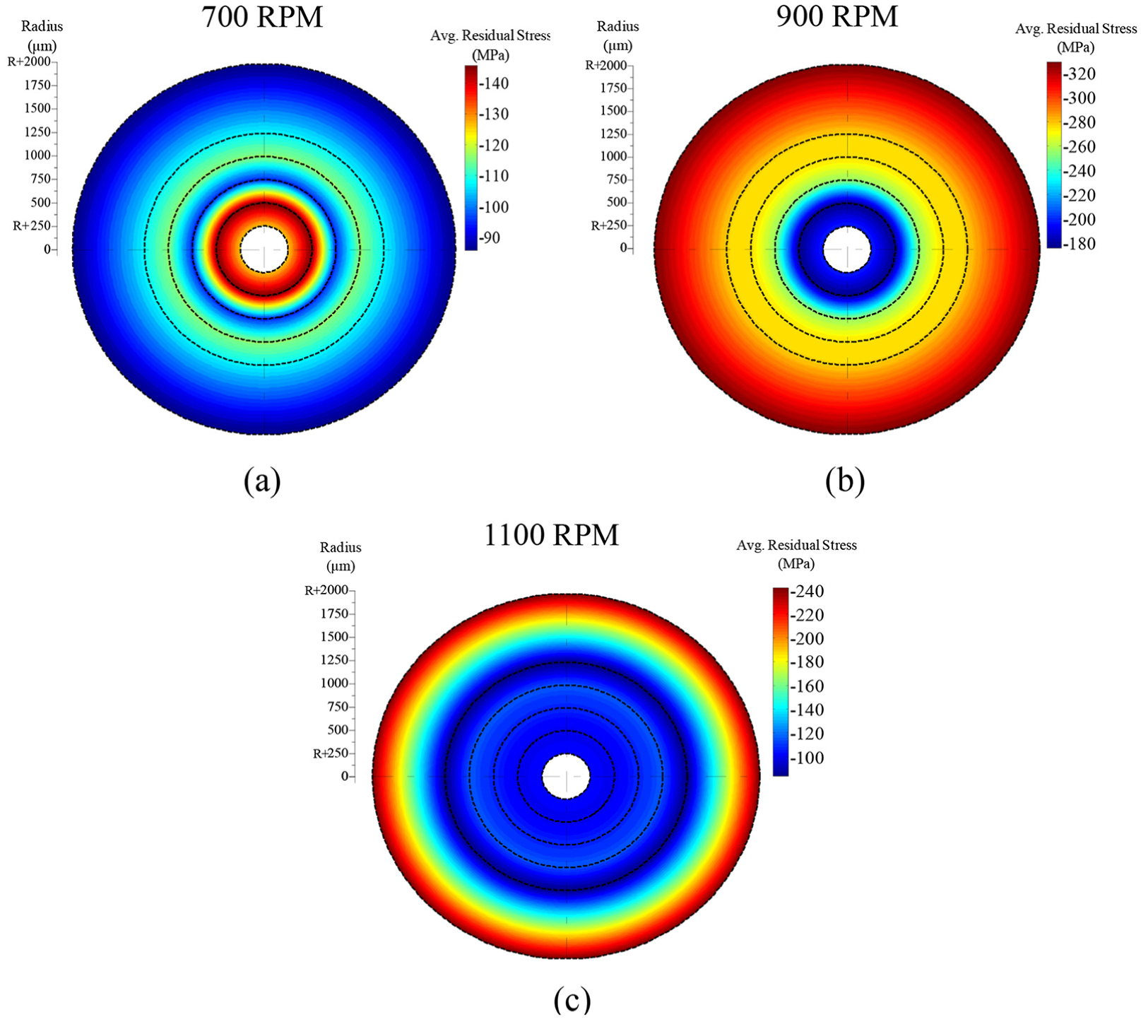
Residual stress distribution near the holes drilled at a speed of: (a) 700, (b) 900, and (c) 1100 r/min, respectively.
The effect of drilling speed on residual stress has been shown in Figure 5. It is evident that maximum residual stress is induced at a drilling speed of 900 r/min as compared to drilling at 700 and 1100 r/min. Stress magnitude considerably increases with an increase in drilling speed from 700 to 900 r/min. Averaged residual stresses fall in a close range up to a radial distance of 1250 μm from the edge of the hole when drilling has been performed at 1100 r/min. Furthermore, low-speed drilling at 700 r/min induces peak magnitude stresses near to the hole’s edge, whereas the same occurs away from the hole’s edge at relatively higher drilling speeds of 900 and 1100 r/min.
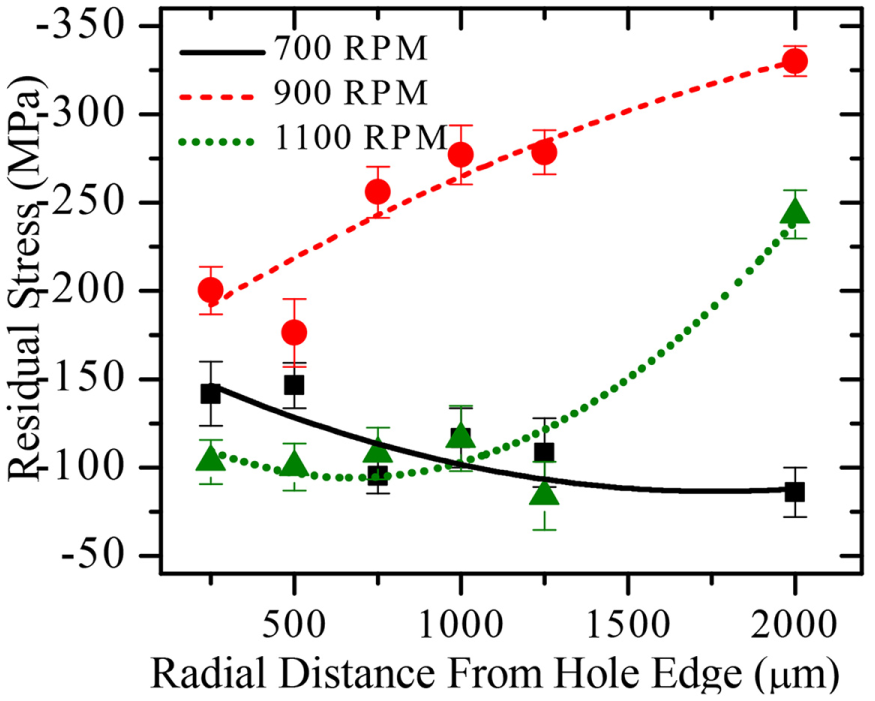
Effect of drilling speed on residual stresses with respect to the distance from the hole’s edge.
Load–depth (P-h) curves obtained from indentations across the sites located at radial distances of R1, R2, R3, and R4, and along the lines oriented at 0°, 90°, and −90°, have been compared for all three speeds (Figure 6). These results suggest the presence of compressive residual stresses near these sites, since the indentation load required to achieve a depth of 250 nm at such locations is greater than that required to penetrate the reference material. The indentation load is maximal across most of the sites near the hole drilled at 900 r/min as compared to those drilled at 700 and 1100 r/min. In addition, P-h curves at these locations for the hole drilled at 1100 r/min are nearly identical; in contrast, P-h curves considerably vary with locations in the samples drilled at 700 and 900 r/min. Evidently, a relative higher speed drilling, specifically at 1100 r/min for mild steel, may result in even distribution of residual stresses near the drilled hole, which is in confirmation with Figure 4.
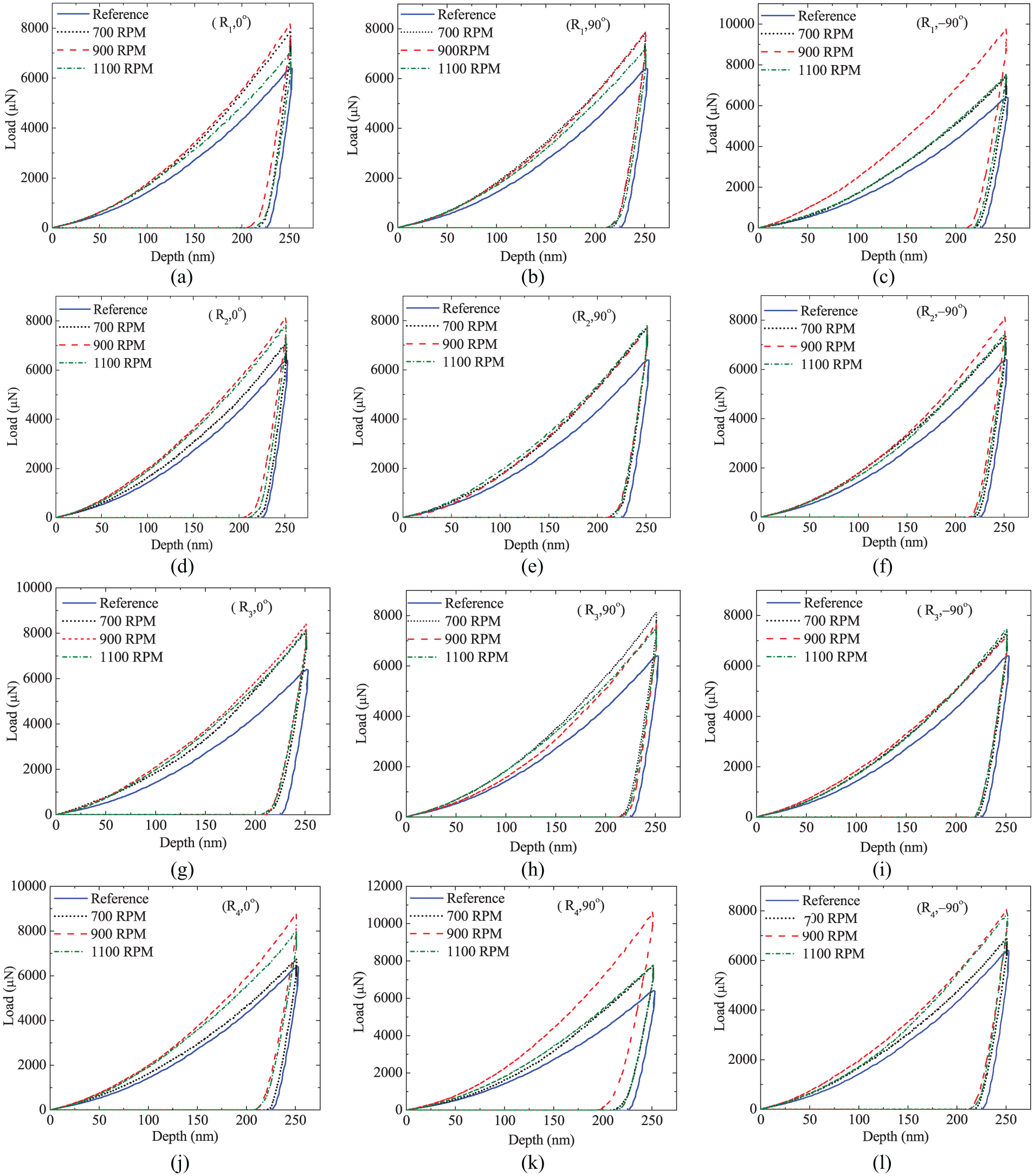
Comparison of load–depth (P-h) curves at sites positioned along the radial lines oriented at 0°, 90°, and −90° and at corresponding radial distances of: (a–c) R1; (d–f) R2; (g–i) R3, and (j–l) R4.
Scanning electron microscopy (SEM) images of cracks initiated across the hole-edge are captured using JEOL JSM-6610LV (Figure 7). The crack width is comparatively small near the hole drilled at 900 r/min (Figure 7(b)), whereas this width increased at 1100 and 700 r/min, successively (Figure 7(a) and (c)). However, the residual stress level was greater near the hole drilled at 900 r/min as compared to that drilled at 700 and 1100 r/min. It suggests that the drilling speed and residual stresses may collectively influence crack attributes. Moreover, the morphology of material near the hole drilled at 700 r/min seems to be more distorted as compared to that noticed at 900 and 1100 r/min. Hence, increased distortions and thus strain hardening and structural reorientation collectively might have resulted into a non-uniform distribution of residual stresses at lower speed. These outcomes align with findings of Ogundare et al., 40 where micro-structural properties of mild steel changed with an increase in strain rate under tensile loading.
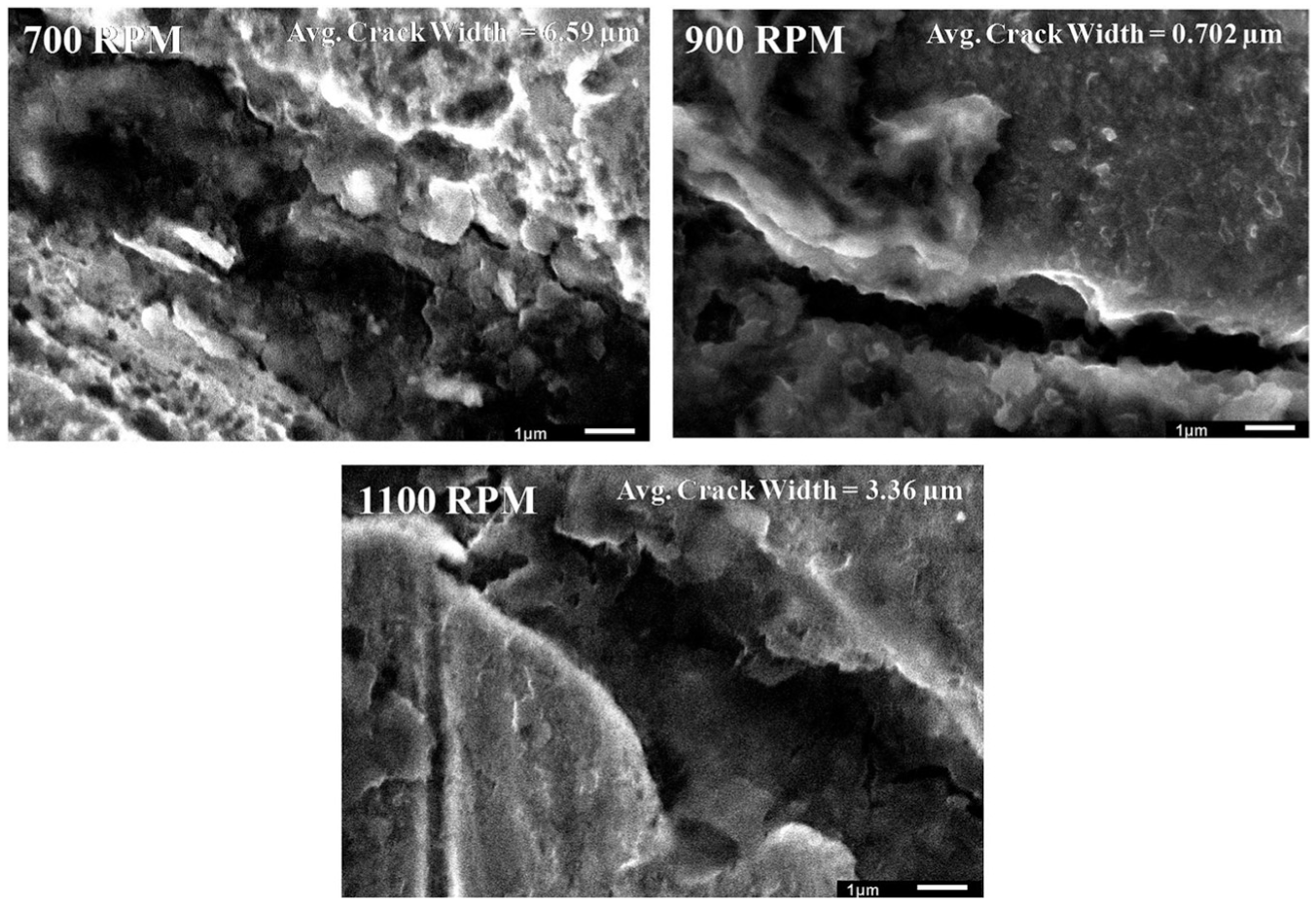
SEM images showing morphological changes in the material near the holes at different drilling speeds.
Discussion
It can be summarized from the results that drilling speed in the range of 700–1100 r/min induces compressive residual stresses around the holes in mild steel. Drilling speed significantly influences the residual stress distribution near the hole, and high-speed drilling may result in an evenly distributed residual stress field. The stress magnitude increases along the radial direction and achieve maximum magnitude at a radial distance of 2000 μm from the edge of holes drilled at higher speed of 900 and 1100 r/min. In addition, drilling parameters and residual stresses may affect the size of a crack initiated near the holes. These findings can be supported by the literature.
Tensile residual stresses are considered detrimental for fatigue life, corrosion, and wear resistance of mechanical parts, whereas, compressive stresses are supposed to be beneficial for the same. Hence, compressive residual stresses are usually introduced using cold expansion methods near the fastener holes to improve their fatigue resistance. Cold expansion induces a local yielding and creates a plastic region near the hole. Chakherlou and Vogwell 19 performed an analytical and experimental study to evaluate the effectiveness of a direct cold expansion technique and suggested that the spring back of elastically deformed surrounding material contracts the yielded material which results in compressive residual stresses. As a result, any crack present nearby the hole will require substantial energy for propagation and so the fatigue resistance will also be enhanced. However, a number of times anticipated benefits of cold expansion method cannot be achieved as tensile residual stresses, and non-uniform distribution of these stresses may also occur. Moreover, Gunnberg et al. 41 also attempted to develop a comprehensive understanding of the relation between cutting data and surface integrity in terms of residual stresses. This study indicated that optimal setting of material removal process parameters such as feed rate may induce compressive residual stresses in the material and may also govern the level, and the distribution of residual stresses. This study substantiates the same in case of drilling operation where the results conclude that high-speed drilling at 1100 r/min may introduce a uniform distribution of compressive residual stresses near the hole, which is desirable for greater fatigue strength. It seems reasonable as high-speed cutting plastically deforms the surrounding material due to tool-part pressure and induces localized plastic deformation. This might have led to compressive residual stresses. Coto et al. 30 indicated that metal cutting operation at high-speed is considered as an adiabatic process where most of the generated heat dissipates through chips. Consequently, minimal tensile residual stresses are generated. Moreover, the high-speed deformation is governed by thermally activated slip, while, diffusional creep governs deformation at lower speeds as indicated by Cottrell. 42 Thus, deformation mechanisms at micro-structural level usually decide the uniform or the non-uniform distribution of residual stresses within the material. 43 Combined effects of high-speed cutting and deformation mechanisms may have produced uniform distribution of compressive residual stresses near the hole. In addition, differences in drilling-induced vibrations at speeds of 900 and 1100 r/min may have produced differences in residual stress magnitude. Interestingly, drilling at 900 and 1100 r/min have induced maximum residual stresses at a radial distance of 2000 μm from the hole-edge, which is similar to the effect usually introduced by cold expansion method. 18 Aghdam et al. 44 also noticed that cold expansion method induces maximum compressive-circumferential residual stress within a distance of 2000 μm from the hole-edge. Such similarities in effects occur as both of these methods (high-speed drilling and cold expansion) may have followed the mechanism of creating a plastic region near the hole. This response is very similar to that has been observed in our previous study, where high-speed deformation/strain rate induced a uniform distribution of residual stresses. 45 This study investigates residual stresses only within the region of 2000 μm, and tensile residual stress may also be present beyond this region (as introduced due to cold expansion method in Chakherlou and Vogwell).18,19 This is a limitation of our study. However, it can be noticed that most of the studies in the literature introduced compressive residual stresses in the region of 2 mm or 2000 μm which suppressed the crack growth originating exactly near the hole and also improved the fatigue strength near the hole. This encouraged us to limit our zone of investigation within a radial width of 2000 μm. Moreover, the effect of far-field tensile stresses will have less impact on the crack growth and the propagation or fatigue strength than residual stresses induced exactly near to the hole-edge. This work, however, does not estimate the residual stress distribution along the hole axis. It may be interesting in future to compare the distribution of residual stresses originated in longitudinal and transverse directions of drilled hole which may explain the critical role of directional residual stresses in the fatigue performance of drilled holes.
Drilling speed governs the amount of plastic deformation at micro-structural level and hence regulates residual stress level near the hole; whereas, the width of crack also depends on the state of plastic deformation. Therefore, the state of crack initiation can be regulated by controlling the drilling process parameters or residual stress field. A similar effect has been observed in this study, where drilling speed or residual stress level affected the crack width. Residual stress distribution considerably affects the crack-growth behavior; hence, optimal selection of drilling parameters may generate beneficial stress distribution to impede the fatigue damage, delay the crack growth, and revamp the fatigue resistance.
In addition, this study utilizes the nanoindentation technique, which provides specific information from the micro-scale. Therefore, the information derived from the distribution of micro-residual stresses can be assumed more precise as compared to the details obtained at macro-structural level. Moreover, the stresses at micro-scale are considered to be inconsistent in distribution along the dimension of micro-structural elements such as grains and particles, whereas, macro-residual stresses vary smoothly along the dimension of a body. 2 In future, relatively high-resolution methods such as focused ion beam (FIB) milling and imaging 46 may also be utilized to obtain the precise distribution of residual stress near the drilled hole.
This study suggests that drilling parameters, such as speed, can be controlled and optimized to improve residual stress state near a drilled hole. Drilling speeds selected here fall in a close range which is a limitation. Thus, it is required to extend this study to industrial range of drilling speeds. Such attempts at laboratory may be accounted as a small step to understand the effect of drilling parameters on residual stress generation and distribution. However, investigation of other parameters such as feed rate, point angle, drill diameter in future will make the conclusions more promising for real-world challenges. Finally, these findings may aid in design and development of effective measures to prevent fatigue strength of holes which lead to 50%–90% failure instance in aircrafts.
Conclusion
This study investigates the effect of drilling speed on micro-scale residual stress distribution near the hole. The findings can be summarized as follows:
Drilling speed considerably influences residual stress field near the hole.
High-speed drilling may distribute compressive residual stresses evenly around drilled hole and which is typically preferred for higher fatigue strength.
Drilling speed and residual stress level may also regulate the characteristics of crack nucleation around the hole.
This study contributes toward establishing a robust relationship between residual stress distribution and drilling process parameter such as speed; however, the effect of several other parameters such feed rate and drill diameter are required to be investigated to precisely substantiate the findings.
These findings may assist in overcoming the limitations of cold expansion method. Moreover, additional methods can be developed to generate tailor-made beneficial residual stress field near the fastener holes so that the fatigue performance of mechanical components can be improved.
Footnotes
Acknowledgements
The authors acknowledge IIT Ropar for providing the financial assistance to conduct this research.
Declaration of conflicting interests
The author(s) declared no potential conflicts of interest with respect to the research, authorship, and/or publication of this article.
Funding
The author(s) received no financial support for the research, authorship, and/or publication of this article.