
Abstract
Direct current motors are used for blower fans as well as for many other systems in vehicles. In this study, it was suggested to use an asynchronous motor instead of the direct current motor for the blower fan. Therefore, an induction motor driver was designed. The purpose of designing this driver was to allow the use of asynchronous motors instead of the brushed direct current motors utilized in automotive ventilation systems. Power and control circuits were designed. A three-phase variable frequency voltage was obtained using an inverter circuit designed with metal-oxide-semiconductor field-effect transistor semiconductor elements from the direct voltage. The voltage/frequency control method was applied to the induction motor. The power circuit was designed using three npn-type and three pnp-type metal-oxide-semiconductor field-effect transistors, in order to reduce the number of independent sources. The direct current motors generally used in automotive ventilation systems have 12 V operating voltage, so the driver was designed to be used in the 12–18 V range. In this study, the alternating current driver was used for a 90 W asynchronous motor and drive at 12 V and 18 V variable input voltage values. The dsPIC33fj32mc204 microcontroller was used to achieve variable frequency and speed control.
Keywords
Introduction
Today, vehicle technology is rapidly evolving and attention to comfort enhancement is increasing. As the technology in vehicles develops, more and more electronic drivers and motors are needed. Motors are designed to be used in power steering, the engine cooling fan, fuel/water pump, air-conditioning compressor, and heating, ventilating, and air conditioning (HVAC) blower systems.1–3 Therefore, there are many motors inside a modern car and most of them are brushed direct current (BDC) motors. One significant reason for the widespread use of direct current (DC) motors is the ease of the DC motor control process and driver design. However, considering the disadvantages of DC motors such as the high initial cost and increased operation and maintenance cost due to the presence of the commutator and brush gear, it would be sensible to use a motor type that is low cost and low maintenance. The most widely used electric motor type in the industry is the asynchronous motor due to the fact that it has low cost, high durability, low maintenance requirements, and does not contain brushes and collectors. The disadvantages caused by the DC motor can be eliminated using an asynchronous motor.4–9 Despite these superior features of asynchronous machines, the control operations of asynchronous motors are quite complex, 10 so the design of the asynchronous motor driver, which is required for the speed control operation, is difficult. At the same time, the efficiency of motors is increased by controlling the speed with the use of these drivers. 11
In related studies in the literature, it is seen that nearly all applications related to the ventilation systems of vehicles contain BDC and brushless direct current (BLDC) motors.12–15 Malakondaiah Naidu designed, built, and tested a semi-integrated sensorless permanent magnet (PM) brushless motor drive for an automotive 42 V HVAC compressor over a wide speed range at different loads. 10 Jianwen Shao presented a method for the microcontroller to detect the BLDC motor rotation. Some techniques for automotive applications such as motor-rotation detection and current sensing have been proposed. 16 Jun-Hyuk Choi designed and presented an implementation of a 42 V BLDC motor for a cooling fan application. Through the experimental results, the validity and quality of the reported designs were verified, and the developed motor demonstrated a nearly 20% improvement of efficiency in the condition with the coupled cooling fan, compared with the present 14 V brush-type DC motor. 17 Wei Cui et al. 18 presented a sensorless bifilar-wound permanent magnet brushless direct current (BW-PMBLDC) motor fan for automotive engine cooling applications. It seems that the number of works on the use of alternating current (AC) motors in vehicles has increased steadily. As high reliability and maintenance-free operations are prime considerations in automotive applications, induction motors have become attractive. 19 Demba Diallo reported that induction motor drives have been increasingly used as mission-critical components in high-performance automotive applications, and he described a fault-tolerant control system for a high-performance induction motor drive. The proposed system adaptively changed the control techniques in the event of sensor failures. 20
Asynchronous motors can be driven using scalar or vector control techniques. 21 Commonly used techniques are direct torque control and voltage-frequency control techniques. These control techniques are included in vector and scalar control methods, respectively. Direct torque control method is complex in terms of control process but efficiency is higher than voltage-frequency control technique. However, voltage-frequency control technique is widely preferred and used in terms of ease of application and control.22,23
V/F control technique is one of the commonly used control techniques in the control of induction motors. Different studies based on V/F induction motor control method are available. Some of these studies are related to power factor correction, solar pump, and induction motor (IM) driver applications.24–26
The advantages of AC motors and the increasing number of DC motors used in vehicles have made it more sensible to use AC motors instead of the latter. The realization of a driver design will allow more use of AC motors in automotive applications in place of the BDC motors used in automotive ventilation systems. For this purpose, in this study, inverter and control circuits were designed. A three-phase variable frequency voltage was obtained using an inverter circuit designed with metal-oxide-semiconductor field-effect transistor (MOSFET) semiconductor elements from the direct voltage. The V/F control method was applied to the induction motor. The power circuit was designed using three npn-type and three pnp-type MOSFETs. The use of these npn- and pnp-type MOSFET transistors was intended to reduce the number of independent sources. Thus, in the design of the IM driver circuit, there is no need to use MOSFET driver integrated circuit (IC) based on different circuit topology techniques (bootstrap, totem pole) or the use of isolated voltage sources from each other. Thanks to this circuit topology, low-cost and uncomplicated driver circuits can be designed and applied to vehicle systems. At the same time, no study has been found in the literature for asynchronous motor use of vehicles instead of dc motors in ventilation system. Different perspective has been formed with this study. In this way, it has formed the basis of different studies related to this field in the future.
The DC motors generally used in automotive ventilation systems have 12 V operating voltage, so the driver was designed to be used in the 12–18 V range. In this study, the AC driver was used for a 90 W asynchronous motor and drive at 12 V and 18 V variable input voltage values. The dsPIC33fj32mc204 microcontroller was used to achieve variable frequency and speed control.
Materials and method
Motor types used in automotive and components of automotive cooling systems
Today the number of motors used in a car has been increasing in the automotive industry because of the automation, enhanced safety, and luxury benefits. Motors are commonly used for electric power steering, brakes, engine and transmission, and ventilation systems applications. The worldwide revenue for electric motors in automotive applications is expected to increase from $26 billion in 2014 to $30 billion in 2019. In 2014, approximately 69.2% of electric motors in automotive applications were BDC, and 13.8% were BLDC. 27 These data clearly show that BDC motors have an important place in the automotive industry market. Figure 1 shows an overview of the areas where BDC motors can be used in a car. 28
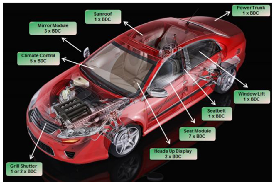
BDC motor applications in a vehicle. 25 .
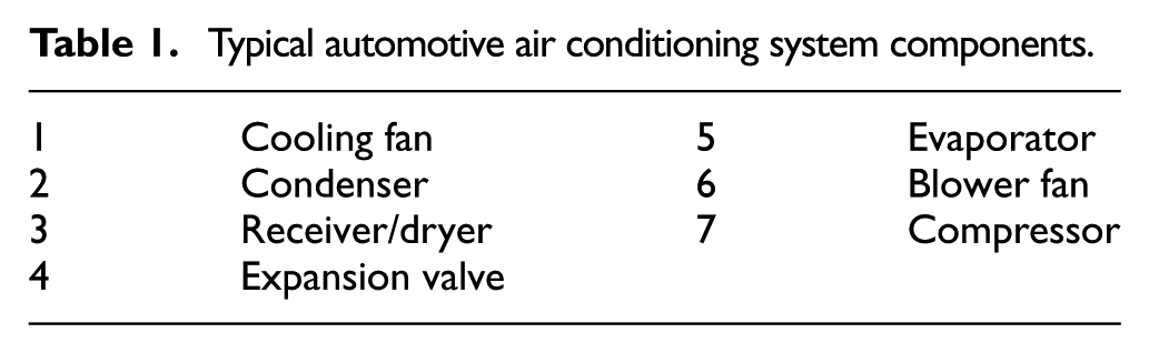
Typical automotive air conditioning system components.
Automotive air conditioning systems are used to produce and distribute cool or hot air inside the car. There are two main areas and the conditioning systems exchange heat between these areas, in each of which a heat exchange device is needed. One heat exchanger, known as the air conditioning condenser, is located at the front of the car, generally in front of the radiator. Another heat exchanger is located inside the front part of the car and is known as the air conditioning evaporator. An air conditioning compressor compresses the gas which is contained in the system and sends it to the condenser.
When the vehicle moves forward, air passes through the condenser. The compressed gases are cooled and transformed into a liquid form. At the receiver/drier part of the air conditioning system, this liquid gas moisture is removed, after which the cooled liquid passes to the expansion valve. This valve expands and converts the cooled liquid to a cold gas. Meanwhile, the evaporator collects heat from the car’s interior. At the same time, the blower fan disperses the cold air inside the car. At the end of this process, the gas travels back to the compressor. This cycle of events repeats itself continuously to cool the car. 13 The air conditioning system can be seen in detail in Figure 2.
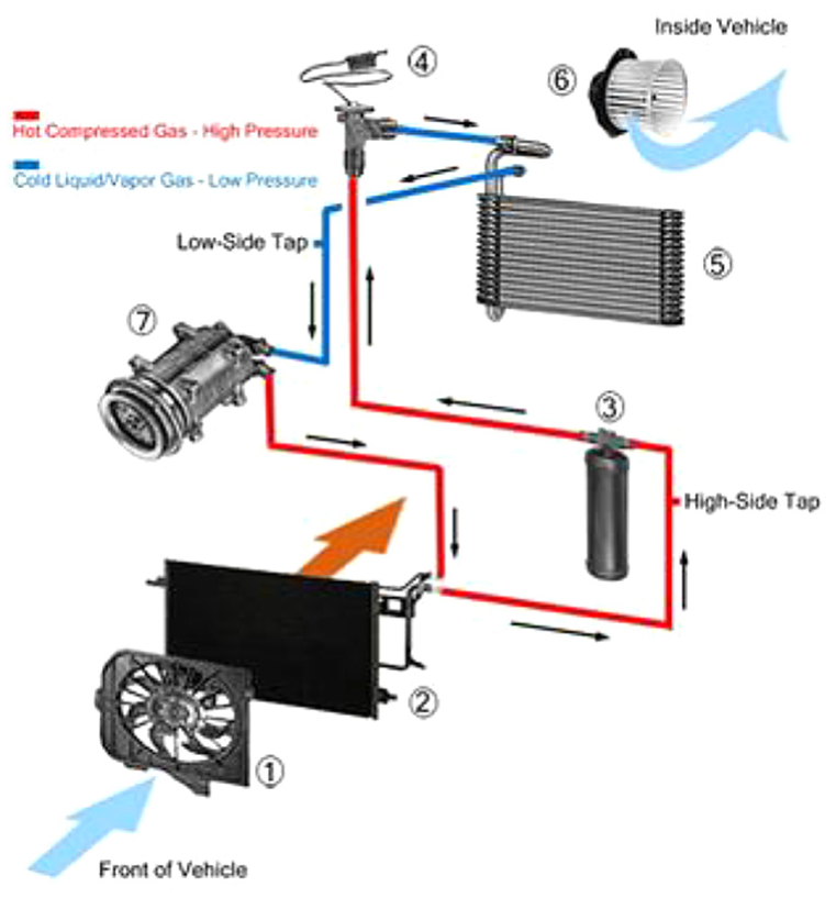
Automotive air conditioning system. 29 .
Three-phase asynchronous motors and control
In this study, it is proposed to use asynchronous motors instead of DC motors in the vehicle air conditioning system as blower motors. The most important reason for choosing an asynchronous motor in the proposed system is that it is cheap and durable. Also, this type of motor does not require much maintenance and its speed is not greatly affected by load changes. In parallel with the increasing preference for asynchronous motors, control methods are also evolving.
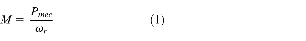
The motor can be operated at a constant speed by increasing the torque when the load is increased and decreasing the torque when the load is reduced. The torque can be controlled by keeping the amplitude and frequency of the applied voltage on the asynchronous motor at a certain rate. The motor speed can be controlled by increasing or decreasing the motor frequency without deterioration of the voltage/frequency ratio. In addition, with the voltage/frequency ratio constant, the current drawn by the motor is also limited. The moment of the three-phase asynchronous motor is given in equation (1)
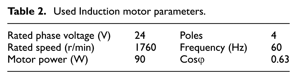
The characteristics and features of the used induction motor are given in Table 2.
Used Induction motor parameters.
Microcontroller
In recent years, microcontroller products have begun to come to the forefront because of their applications in industry, education, health, defense, communications, and so on. Combining the control features of microcontrollers with the computational and efficient operation of digital signal processors (DSPs) into an embedded system, the dsPIC microcontrollers were first marketed by Microchip in 2005. The dsPIC33fj32mc204 is a 16-bit microcontroller with a reduced instruction set computer (RISC) architecture that was marketed and updated in 2005 by Microchip. Some of the technical features of dsPIC33fj32mc204 are presented in Table 3.
Features of dsPIC33fj32mc204.
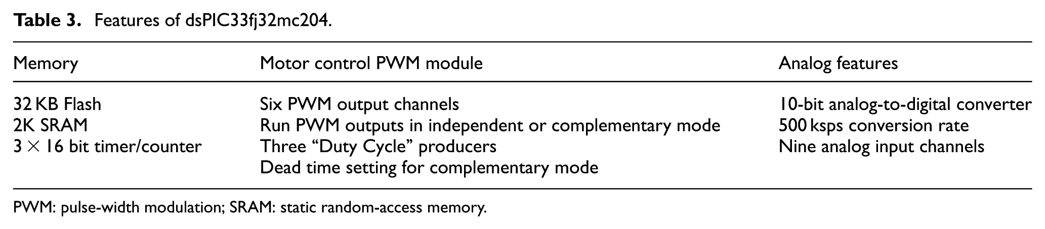
PWM: pulse-width modulation; SRAM: static random-access memory.
The dsPIC33fj32mc204 is mainly used in the drive of three-phase asynchronous motors, uninterruptible power supplies, BLDC motors, and switched reluctance motor drive circuits. The dsPIC’s motor control pulse-width-modulation (PWM) module and encoder module are designed to be used in these areas.
Motor control PWM module
The motor control PWM module is able to produce solutions by means of independent PWM channels for driving multi-phase motors such as asynchronous motors and BLDC motors at variable speeds. The PWM outputs of the module can optionally be used in stand-alone mode or in complementary mode. In complementary mode, the PWM output pairs are produced as opposed to each other and switching of the upper and lower arms in the driver circuits with semiconductor switching can be done. The PWM period of the motor control PWM module of the dsPIC microcontroller is calculated according to equation (2). 30

In equation (2), PTPER (PWM time base period register) is the recorder where the period will be saved, Fcy is the microcontroller clock frequency, FPWM is the desired PWM frequency, and the PTMR (PWM time base register) prescaler is specified as the scale of the PWM timer.
Dead time module
When the motor control PWM module is used in the complementary mode, the dead time (DT) generator is designed to prevent the lower and upper semiconductor elements from being in the same conduction. The DT generator activates the other output when one of the PWM pairs has exited the conduction after a certain period. When the DT is selected to be longer than the semiconductor elements switching time, the upper and lower arms cannot be in the same conduction, thereby preventing short-circuiting of the source and preventing failures. 31 The DT calculation formula for the dsPIC motor control PWM module is given in equation (3)
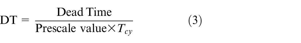
Equation (3) shows that Tcy is the microcontroller time period, DT is the value of DT in microseconds, prescale value is the value of the time period, and DT is the value to be written to the DT register.
Implementation of variable voltage and frequency control AC driver system
System overview
The three-phase induction motor driver system has the DC source, a three-phase full bridge inverter circuit, a control circuit, and three-phase asynchronous motors. In the proposed work, a three-phase asynchronous motor driver was designed with six MOSFET switches. The driver circuit output was applied to the three-phase asynchronous motor, which was controlled according to the V/F control method. The speed of the motor was controlled via the control circuit potentiometer. The generated PWM signals used for controlling the MOSFETs were applied to each of the MOSFET gates through the TLP250 opto-coupler.
Power circuit
The power circuit was designed using three npn-type and three pnp-type MOSFETs. The pnp-type MOSFETs formed the upper arm, and npn-type MOSFETs formed the lower arm. If the upper and lower switches of the same leg were switched on at the same time, this would cause the DC bus supply to short-circuit. To prevent this situation, DT must be given between switching off the upper switch and switching on the lower switch. The use of npn- and pnp-type MOSFETs was intended to reduce the number of independent sources. These MOSFETs were driven using a TLP250 opto-isolator. The MOSFETs were protected against surge voltages using 20 V Zener diodes between their gate and source pins. The ACS-712 current sensor was located on the driver circuit and prevented the motor from overheating when it was exposed to overcurrent for a long time. The three-phase induction motor was selected as 90 W power and 24 V input, and a three-phase bridge inverter circuit output was connected directly to the three-phase asynchronous motor.
Control circuit
In this work, Microchip’s dsPIC33fj32mc204 digital signal controller was used. The control card was designed for applications requiring PWM signals. A potentiometer was connected to the analogue input of the microcontroller. The speed of the motor could be changed by adjusting the V/F ratio through this potentiometer. Furthermore, the liquid-crystal display (LCD) could be connected to the control card with the removable and attachable LCD connection cable. With the light-emitting diodes (LEDs) connected to the outputs of the PWM ports, it was possible to see visually whether the PWM signal was produced or not. Three pairs of PWM signals operating in complementary mode could be obtained by means of the control circuit. PWM signal pairs were obtained as high (H) and low (L). High PWM signals were applied to the upper arm of the three-phase bridge inverter circuit and low signals were applied to the lower arm. The DT was selected as 8.4 µs. The PWM signal was determined as 5 kHz and the microcontroller was operated at 80 MHz with maximum speed capacity. Frequency change could be observed on the LCD screen using a potentiometer at the 0–64 Hz range. The PTPER value can be calculated as in equation (4)

The DT value can be calculated as 8.4 µs in equation (5)

The designed and implemented driver system block schema can be seen in Figure 3. The system input voltage range was determined as 0–24 V. According to the applied voltage value, it was changed to different voltage levels and for this voltage conversion, LM317, 7805, and 7812 voltage regulators were used. Six TLP250 MOSFET drivers were used in total for each MOSFET switching. The MOSFETs were controlled using the V/F control method. The ACS-712 current sensor was used in order to prevent damage to the driver circuit and asynchronous motor in case of overcurrent. The asynchronous motor speed control could be adjusted by means of a potentiometer.
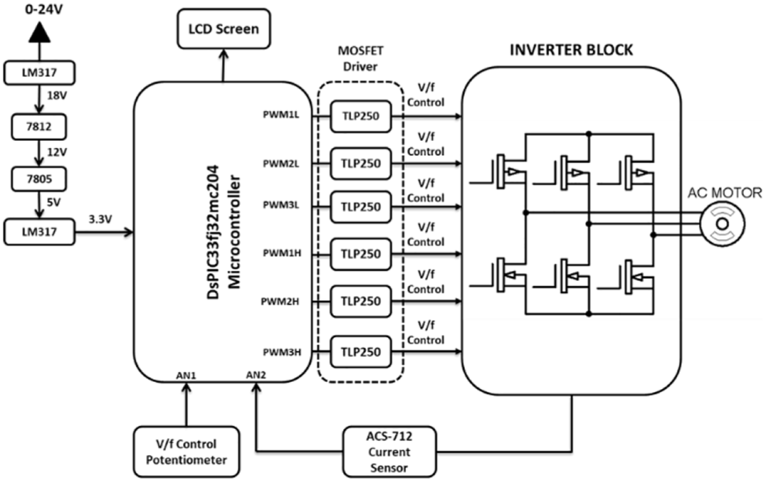
Power and control circuit block schema of asynchronous motor driver.
dsPIC algorithm for asynchronous motor driver application
The dsPIC-based algorithm developed for intended application in asynchronous motor drivers is depicted in Figure 4. The P1TPER (PWM time base period register), P1DTCON1 (DT register), and FPWM (PWM signal frequency) values were set to, respectively, 7999, 84, and 5 kHz as the initial setting.
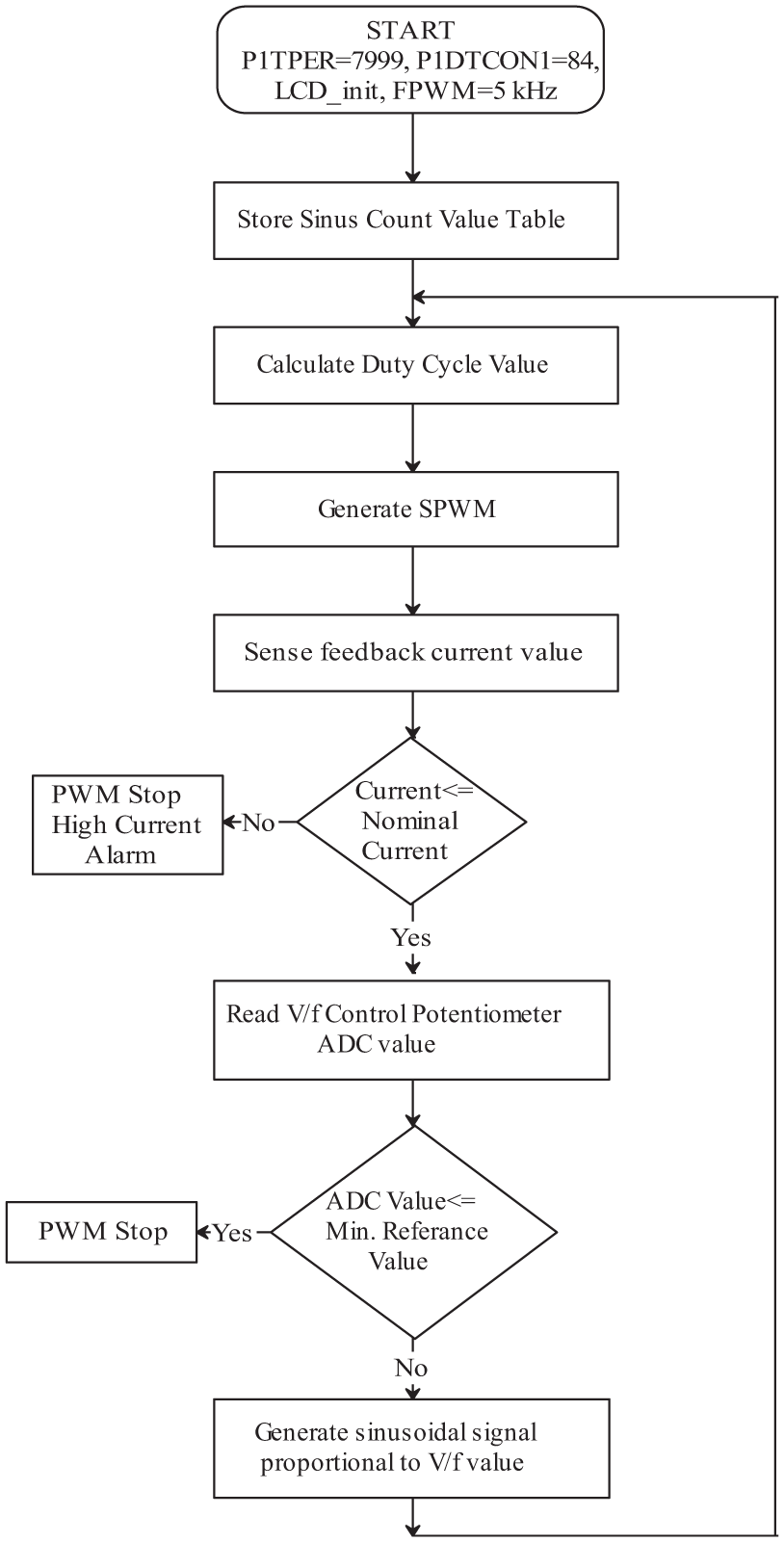
dsPIC-based three-phase asynchronous motor driver circuit control algorithm schema.
PCB design using surface mounted technique and through-hole technique
The control and power circuits were printed on an integrated circuit card. Thus, the motor driver system was turned into an industrial card using surface mounted technique (SMT) circuit components. The Proteus program was used for the card design process. The Proteus program design of the motor driver circuit can be seen in Figure 5 and the real-time designed printed circuit board’s (PCB) front and back view are shown in Figure 6. The complete three-phase asynchronous motor driver system is shown in Figure 7.
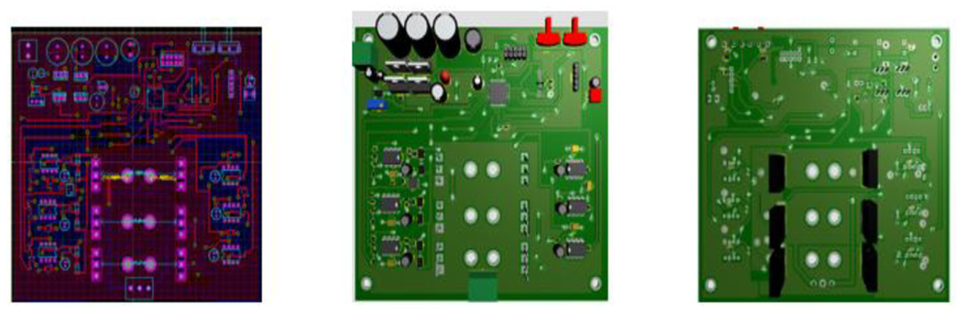
Designed three-phase asynchronous motor driver card at Proteus program.
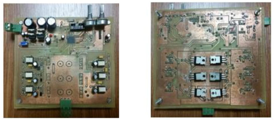
Designed three-phase asynchronous motor driver card.
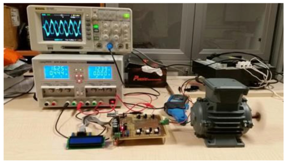
Three-phase asynchronous motor driver system.
Experimental results and discussion
In this study, the three-phase, 90 W asynchronous motor was operated at input voltages of between 12 and 18 V with the designed asynchronous motor driver circuit. The three-phase drawn current and voltage shapes are given in the following part of the paper. The current and voltage shapes were taken at 12 V and only the voltage shapes were taken at 18 V operation. At the signal waveform of the oscilloscope, a square indicating the signal amplitude corresponds to a value of 5 V. When the oscilloscope voltage waveforms are examined by zooming, it is seen that the amplitude of the voltage signal is more than three squares. Also, this corresponding voltage values are approximately 18 V. Figure 8 show each phase’s voltage oscilloscope view for the 18 V asynchronous motor in the case of no-load operation. As can be seen, sine signals are generated by the sinusoidal pulse width modulation (SPWM) method in PWM signal mode. These signals can be considered as distorted, but when the current signals were examined, they were seen as a pure signal shape. The reason for this is that the windings of the motor serve as a resistor-inductor (RL) filter. Thus, a current signal is properly generated from the voltage signal but appears to be a distorted shape. Three phases drawn current waveforms measured in same time (10 ms) for same A/div (5 V) conditions and given in Figure 9. These current waveforms measured under 12 V source voltage value and no-load operations conditions. The drawn current value in Figure 9 is 1 A and three phases current waveforms can be seen, respectively, with different colors. It was observed that the current drawn increased as the V/F control potentiometer that controlled the motor speed was increased.
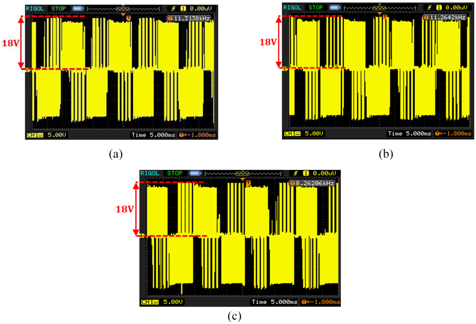
(a) First phase voltage shape (18 V, 60 Hz). (b) Second phase voltage shape (18 V, 60 Hz). (c) Third phase voltage shape (18 V, 60 Hz).
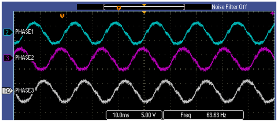
First, second and third phase drawn current shape (12 V, 1A, 64 Hz).
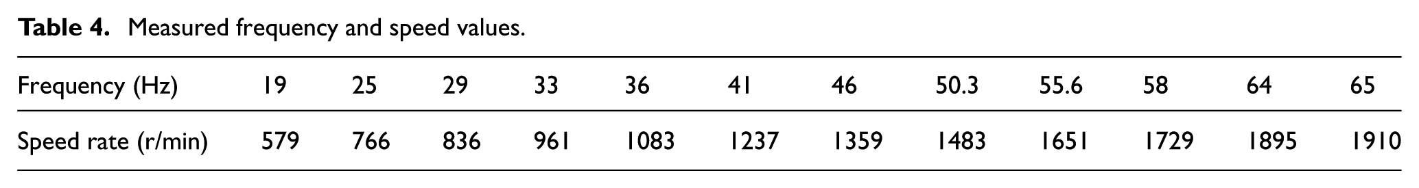
The speed values of the induction motor at different frequencies were measured and given in Table 4. The frequency range is 19–64 Hz, and the speed values range from 579 to 1910 r/min.
Measured frequency and speed values.
The control methods of AC motors were mentioned. These methods were mainly classified as scalar and vectoral. To compare this study with different control methods in literature, vector control based methods are used in AC motors or different types of motors in many studies. 32 The efficiency of vector control based control methods is higher than the V/F method. However, in this study the efficiency is in the second plan. Because a motor in the ventilation system works when needed that does not work continuously.
The main aim was to create a different perspective and focus on the applicability of the control method. Therefore, V/F control method was used in scalar control methods. In future studies, one of the vector control methods can be used to control the engine in the same ventilation system.
Another unique aspect of the study is that MOSFETs can be controlled without the use of driver IC circuits or without isolated source requirement. For applications, MOSFET requires different types of IC uses for switching.33,34 The circuit topology used in this study was used for switching without the need of these circuits.
Conclusion
It is recommended in this study to use asynchronous motors instead of DC motors in vehicles. This has not been widely suggested in the related literature or other studies on this field. In line with this idea, an asynchronous motor driver circuit was designed and implemented successfully. In the experiment, the driver circuit was tested in the 12–18 V input voltage range. This driver circuit contained control and power circuits on the same card. A dsPIC33fj32mc204 microprocessor was used as a controller and produced the required PWM signals for the sinusoidal signals, implemented a V/F control algorithm, and performed analogue and digital input–output control operations. Three-phase bridge inverter circuit topology was used in this study, in which npn-type MOSFET switching semiconductor elements are used in the upper node and pnp in the sub-node. This reduces the number of different sources required for feeding the switching elements in the power circuit. Speed and torque control of a 24 V, 90 W three-phase asynchronous motor with V/F motor control technique was realized. Current and voltage oscilloscope screen views of the motor are obtained at voltages of 12 V and 18 V. Thus, the designed driver card can be used in industrial systems.
Footnotes
Declaration of conflicting interests
The author(s) declared no potential conflicts of interest with respect to the research, authorship, and/or publication of this article.
Funding
The author(s) received no financial support for the research, authorship, and/or publication of this article.