
Abstract
Interdigital transducer and signal transmission in surface acoustic wave pressure sensor design is one of the difficulties in sensor design. The transmission antenna is an important design indicator to determine the wireless function of the sensor. In this paper, we simulated the design of the interdigital transducer of surface acoustic wave pressure sensor through COMSOL and analyzed the relationship between the eigenfrequency of the single-pair interdigital model and the interdigital electrode. Then, we obtained the design of the interdigital electrode with error of 0.01 MHz. We also simulated the size, bandwidth, impedance matching, and other parameters of antenna through high frequency structure simulator, and a matching dipole transmission antenna was designed and miniaturized. When the bandwidth is satisfied, the control matching impedance error is within
Introduction
Background and research status
Since Rayleigh proposed the concept of surface acoustic wave (SAW) in 1885, a large number of researchers have studied SAWs. Due to the advantages of extremely short wavelengths and propagation speeds, and simple sampling conversion process, SAW has been widely used in communication, 1 medical, 2 environment, 3 and other fields. 4 Because of the working principle of SAW and the advantages of the stability of the base material in pressure and temperature, SAW pressure sensor has the advantages of small size and passive wireless 5 compared with the commonly used pressure sensor. At present, SAW pressure sensors are mainly used for measuring gas and gas pressure changes.6–8 The realization of the wireless function of SAW pressure sensor depends on the design of its matching antenna. Moreover, the design of the SAW pressure sensor transmission antenna is an important factor that restricts the size of the sensor. In the SAW radio frequency (RF) tag design, Lieberzeit et al. 9 used the coding technique to measure the humidity and gas concentration, Chen et al. 10 used the BPSK (binary phase shift keying) code to measure the temperature. Stelzer et al. 11 offer a temperature measurement solution using SAW tags. However, the design of the transmission antenna has not been described in detail in previous reports. According to the design principle of SAW pressure sensor and the design concept of transmission antenna, this paper studies the model of SAW cross-finger transducer and its matching antenna and proposes an optimal design scheme. The solution provides a design idea of a SAW sensor and its matching antenna. It can not only introduce the design method of the interdigital transducer (IDT) better, but also describe the design requirements of the antenna in detail. We propose a feasible method for the signal transmission of the SAW devices.
Design plan
In this paper, the SAW pressure sensor is based on a SAW delay linear structure. The antenna transmits the excitation signal to the IDT, when the pressure on the sensor changes, the SAW will change. The echo signal with frequency and amplitude is transmitted back to the IDT through the reflector, and the magnitude of the pressure on the sensor can be judged by the change of the echo signal. Figure 1 is the schematic diagram of the SAW pressure sensor. This paper focuses on the designs of the SAW pressure sensor IDT and its antenna in the left frame.
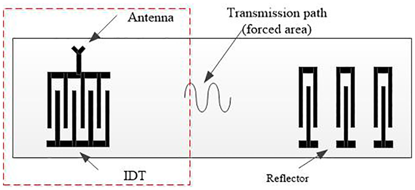
Schematic representation of the delay line–type SAW pressure sensor.
IDT design simulation
The simulation of SAW devices is an indispensable step in the manufacture and development of SAW devices. Simulation can not only improve design accuracy, but also reduce unnecessary material loss. In the simulation of SAW device, the simulation of the IDT is the top priority of the structural design. The IDT can be simulated by establishing a
IDT model establishment
As Figure 2 shows,
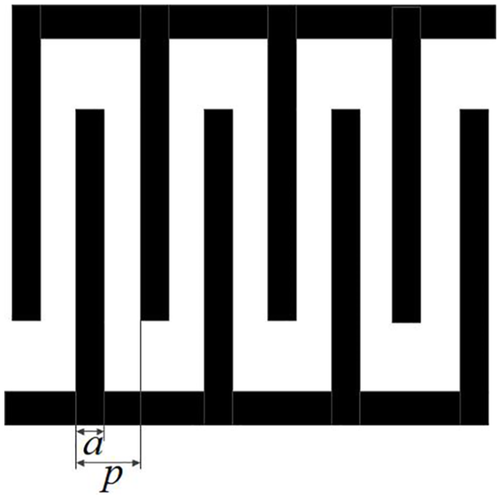
The basic model of the IDT.
When the finger pitch

where
As the process of superimposing multiple IDTs is too complicated, we simplified the cross-finger transducer to a periodic structure of single pair IDT. Figure 3 shows the specific model structure of the IDT. As shown in Figure 3,
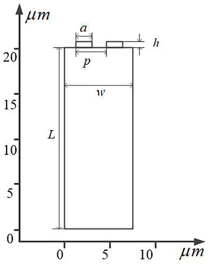
Single pair IDT model.
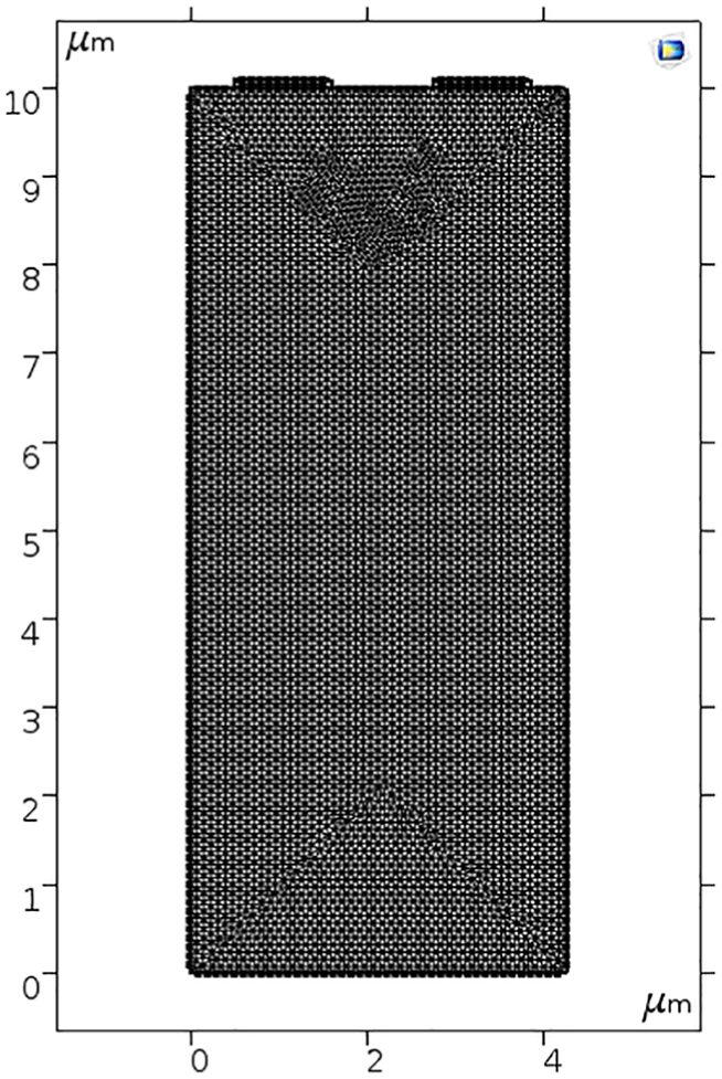
Single pair IDT model meshing.
IDT model simulation results
In the working process of SAW sensor, the signal will cause the piezoelectric substrate to change, which will lead to the change of frequency and phase of the output signal. The eigenfrequency is an important parameter of the SAW sensor. So, we can judge the change of signal to be measured by the frequency change of sound surface wave.
The eigenfrequency of the sensor is set at 915 MHz. The finger pitch p is calculated by equation (1). The metal polarizability
We chose
The initial parameters of the model are shown in Table 1.
Single-pair IDT model parameters.
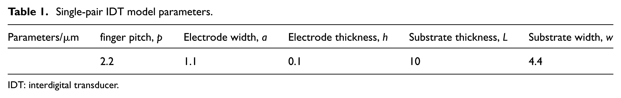
IDT: interdigital transducer.
In COMSOL, the model needs to be meshed. As shown in Figure 4. The model designed in this paper is a single-pair IDT design, and the model meshing selection is extremely detailed. In order to achieve the expected parameter requirements, the eigenfrequency of the IDT is changed by adjusting the metal polarizability. The simulation results of the single pair IDT model are in the following paragraphs.
As shown in Figures 5 and 6, the metal polarizability will cause the offset of the IDT eigenfrequency. We change the metal polarizability from 0.5 to 0.48, and the eigenfrequency of the IDT changes from 915.08 MHz to 914.99 MHz. Therefore, the metal polarizability can be adjusted according to the design requirements to obtain the desired design parameters.
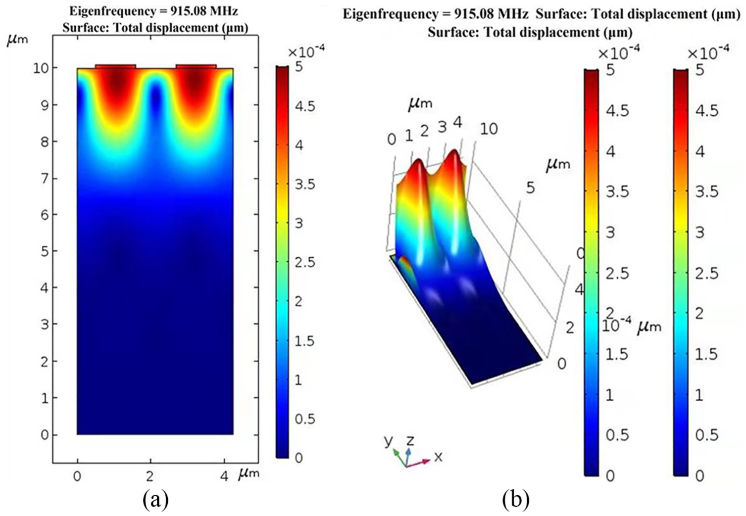
IDT simulation with
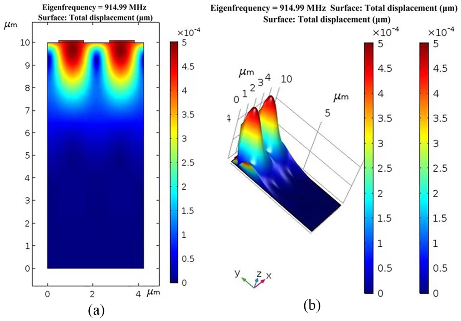
IDT simulation with
Dipole antenna design simulation
The design of SAW sensor antenna plays an important role in the SAW sensor detection system. It will directly affect the signal transmission accuracy of the SAW sensor. Different antennas are suitable for different working environments. By analyzing the design concept of different antennas, we found that the dipole antenna has the characteristics of small size, simple structure, and circular polarization.
13
Therefore, we use the printed dipole antenna as the transmission antenna of the SAW sensor. According to the eigenfrequency requirement of the SAW sensor, the eigenfrequency of the antenna designed in this paper is set at 915 MHz, the bandwidth is greater than 50 MHz at a voltage standing wave ratio (VSWR) of 1.5, and the matching impedance is 50
Antenna model design
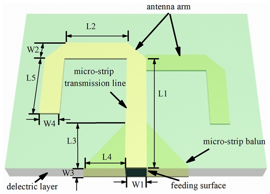
The printed dipole antenna model is mainly divided into an antenna arm, a microstrip balun, a feeding surface, a microstrip transmission line, and a dielectric layer. The specific structure is shown in Figure 7.
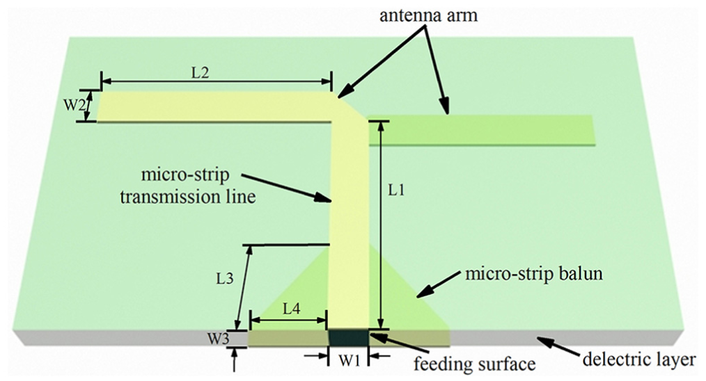
Schematic of the printed dipole antenna model.
The size, return loss, operating bandwidth, and impedance matching of the antenna are crucial to the design of the SAW sensor antenna. We use epoxy glass fiberboard (FR4) as the antenna dielectric layer. FR4 has better electrical insulation and higher dielectric properties. The relative dielectric constant of FR4 is

Where
Antenna model simulation results
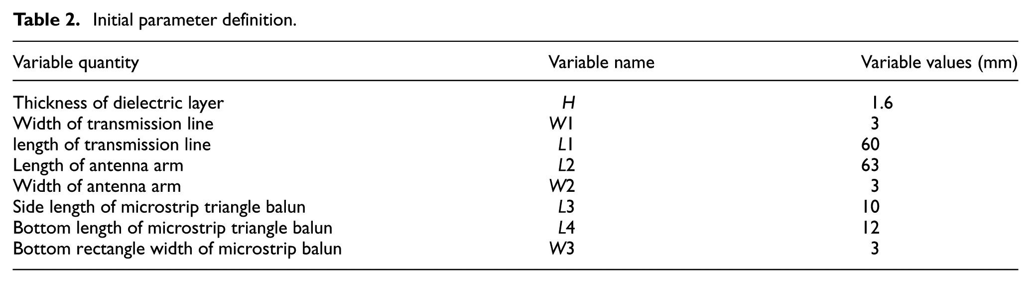
According to the design model of the SAW sensor transmission antenna, the antenna model is simulated by high frequency electromagnetic wave simulation software (HFSS). The initial parameters are shown in Table 2.
Initial parameter definition.
As shown in Figures 8 and 9, when the
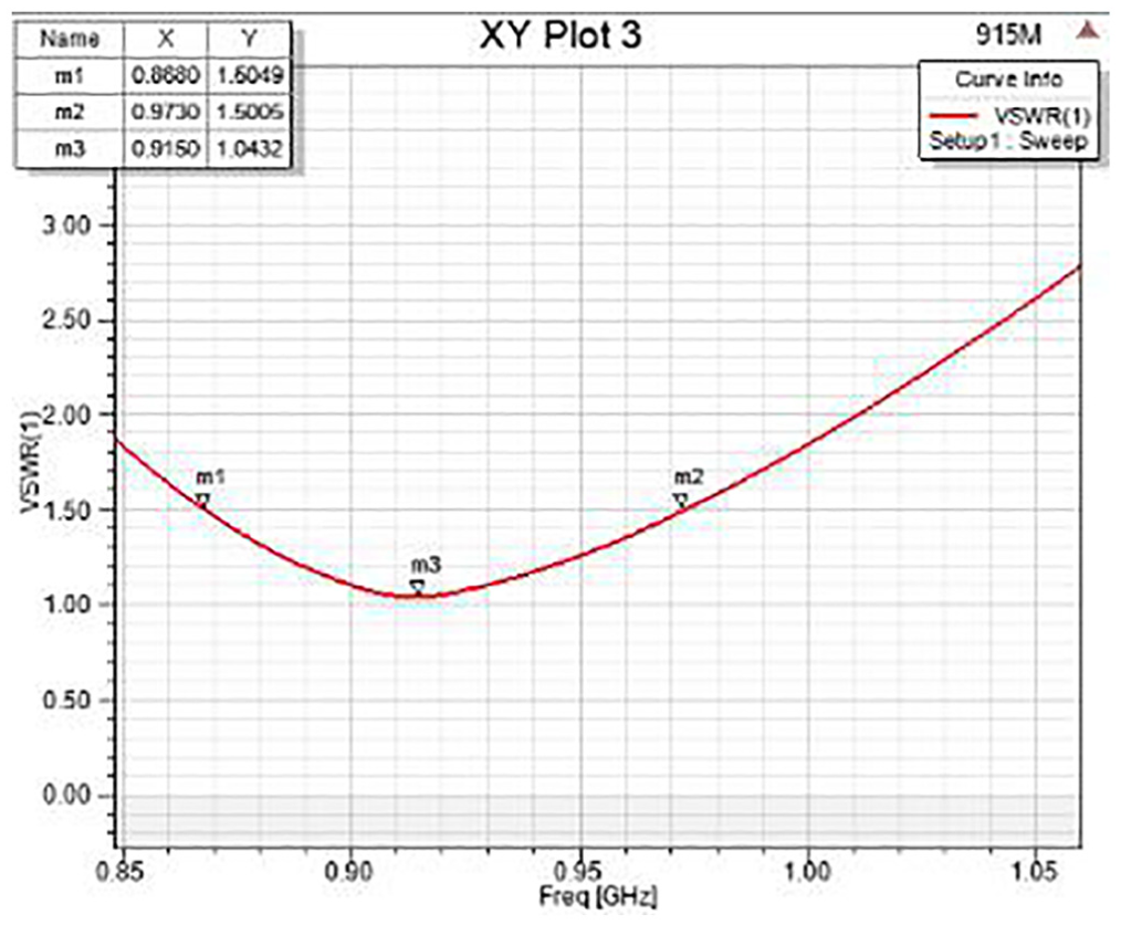
The result of VSWR = 1.5.
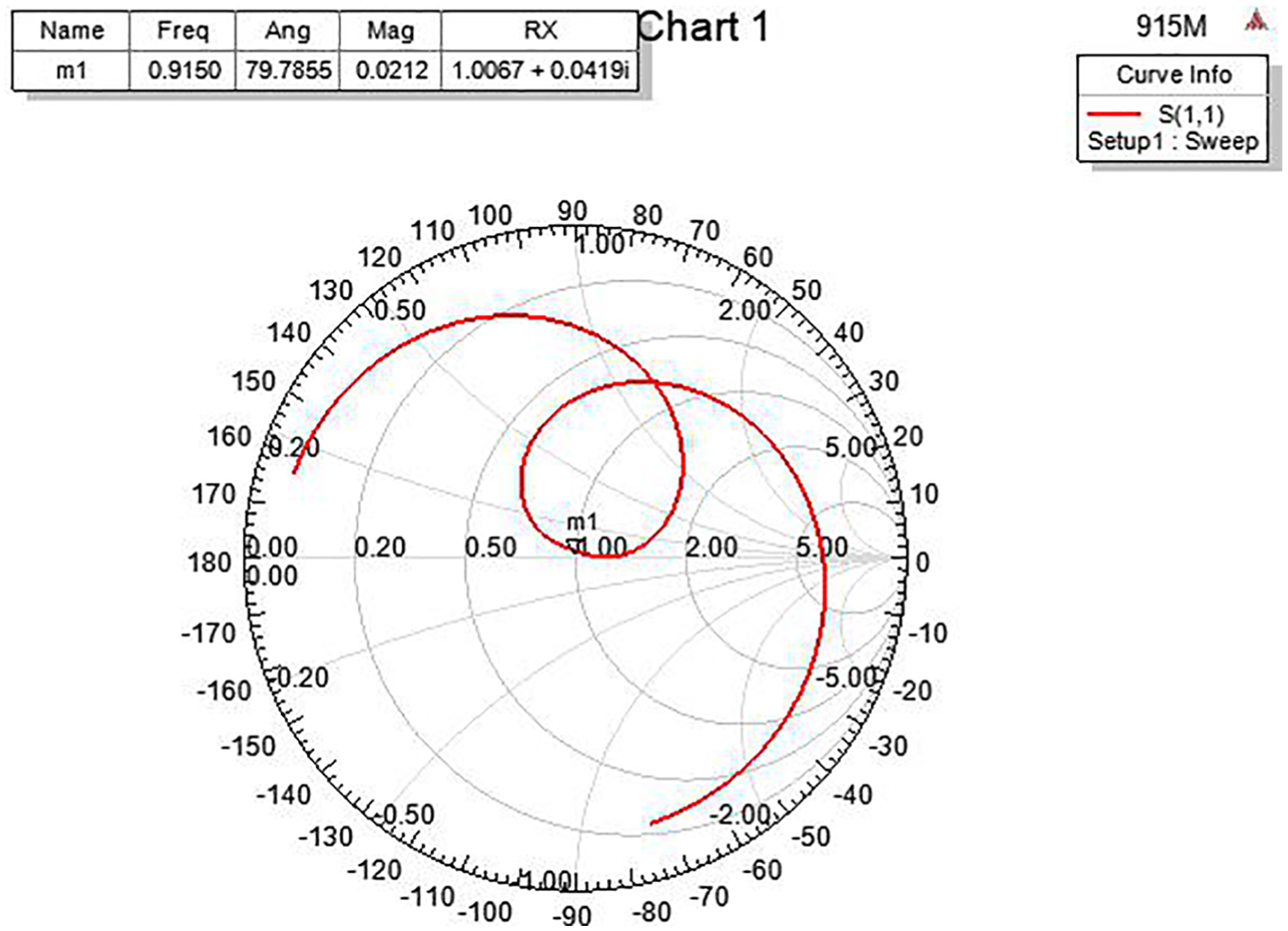
Smith chart.
The transmitting antenna arm length of the SAW sensor directly affects the size of the transmitting antenna. So we use a folded antenna arm to reduce the size. The structure of the miniaturized antenna is shown in Figure 10.
Schematic of the miniaturized antenna structure.
The antenna arm length is simulated by HFSS, and the optimized parameters are shown in Table 3.
Miniaturized antenna size parameters.
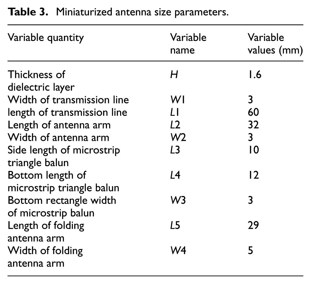
As shown in Figures 11 and 12, when
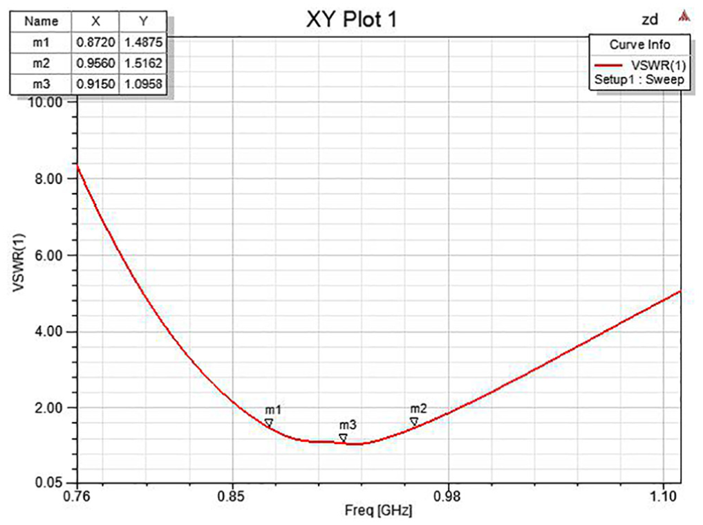
Simulation results of the VSWR after miniaturization.
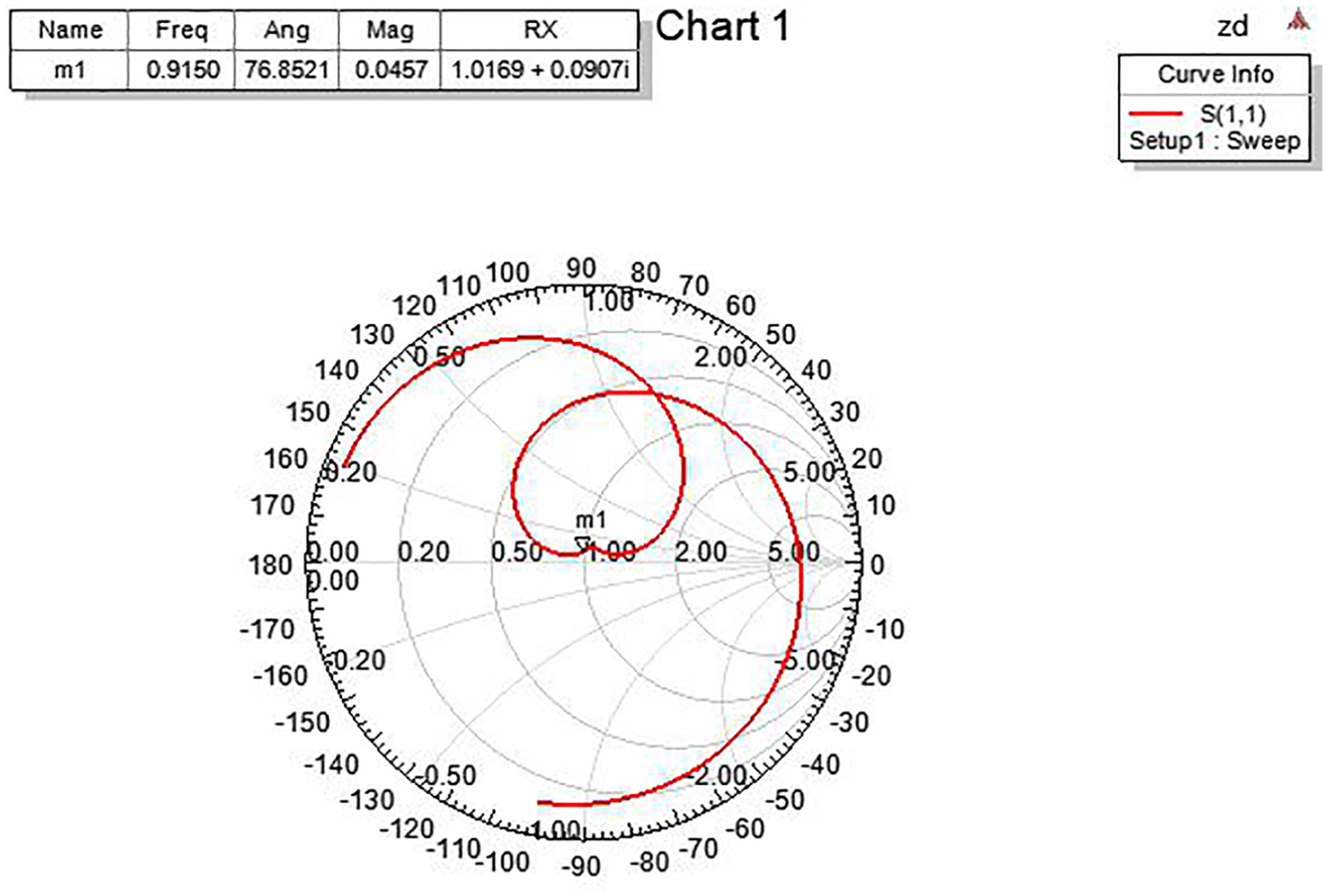
Smith chart after miniaturization.
Conclusion
In this paper, we designed and simulated the IDT and matching antenna of SAW pressure sensor. We used COMSOL to simulate the single-pair IDT of the SAW sensor and determined the specific size of the IDT. By analyzing the frequency response of the single pair of fingers, we studied the influence of different metal polarizabilities on the eigenfrequency of the SAW. Then, the interdigital electrode with the eigenfrequency of 914.99 MHz was designed. The matching antenna of SAW pressure sensor is simulated and miniaturized by HFSS, The paper analyzes the influence of antenna arm length on the center frequency of the transmitting antenna, and finally designs an antenna with a bandwidth of 84 MHz and matching impedance is (50.845 + 4.535j) ohms. It lays the foundation for the next detection system of SAW sensors.
Footnotes
Declaration of conflicting interests
The author(s) declared no potential conflicts of interest with respect to the research, authorship, and/or publication of this article.
Funding
The author(s) declared the following potential conflicts of interest with respect to the research, authorship, and/or publication of this article: The authors would like to express their gratitude to the National Natural Science Foundation of China (61803254) for the financial support provided for this work.