
Abstract
In this paper, a new hybrid robust tracking control for an underwater vehicle in dive plane via
Introduction
Autonomous underwater vehicles (AUVs) are widely used in underwater to explore in great depths. In these vehicles, control systems are required to provide signals to the actuators in order to achieve the desired position and velocity for vehicle. AUV’s dynamic is hard, nonlinear with uncertainty in nature. Therefore, the proposed controller for these systems has to indicate robust accurate tracking performance in the presence of external disturbances and noises. One of the most important techniques for control of AUV is nonlinear control technique. In literature,1–3 many controllers designed for path following based on Lyapunov approach and back stepping technique that nonlinear feedback law yielded that the tracking error approaches to zero. Fischer et al.4,5 developed a nonlinear control method for coupled underwater vehicle using a robust integral of the sign of the error index (RISE).
Adaptive control is a nonlinear control strategy used for uncertain or time-varying systems. This type of control is useful for AUVs due to the changing dynamics in the ocean. The controller can adapt itself to varying ocean currents or to redundant structure when the manipulator is installed. Adaptive control is applied for AUV in many literature.6–14 In Santhakumar and Kim, 15 an indirect adaptive control was developed based on extended Kalman filter (EKF) which provided a generalized framework for indirect adaptive control which considered the dynamic coupling between the vehicle and the manipulator. External disturbances were estimated using EKF. In Antonelli and Cataldi, 16 an adaptive and regressive controller was developed for an arm-equipped underwater vehicle. Simplified implementation and compensation in the presence of ocean current is its advantage. For avoiding acceleration measurement, a reduced regressor is implemented.
Sliding mode control (SMC) is a powerful nonlinear control method. Pure sliding mode controller has disadvantages such as chattering phenomenon and noisy vulnerable properties.
17
Sliding mode with boundary layer control (BLC) is one of the methods to attenuate chattering phenomenon.18,19 In Elmokadem et al.,
20
a trajectory tracking SMC was designed for lateral motion of an AUV, in order to force the AUV to track a time-varying trajectory. For online estimation of external disturbances and uncertainties in AUV, adaptive fuzzy SMC has been used in Marzbanrad et al.
21
AUV’s dynamic systems have uncertainties and external disturbances. The effects of these uncertainties and disturbances enter AUV from different channels to control signals. For avoiding these effects, robust control method and observation method have been implemented.22,23 New terminologies, rejection parameter, and rejection regulator were defined, and a new time-variant sliding function based on time-variant rejection parameter was designed.
24
A robust wavelet SMC via time-variant sliding function and
In this paper, a hybrid robust SMC has been designed which is composed of two simultaneous control signals. The first control signal is designed based on time-variant sliding function. The time-variant sliding function filters all the unmodeled frequencies and external disturbances such as a chain of
This paper is organized as follows. In section “Problem formulation,” equations and the mathematical model of an AUV in dive plane are presented. In section “Design of a new hybrid robust depth control with disturbance observer,” sliding mode with BLC for the AUV is discussed and also the proposed controller and disturbance observer are presented. In section “Simulation results,” the simulation results are analyzed in the presence of parameter uncertainties, external disturbances, and noise for the proposed controller, sliding mode with BLC, and super twisting sliding mode control (STSMC) in Ismail and Putranti 28 and Cui and Zhang. 27 Finally, section “Conclusion” concludes the paper.
Problem formulation
The underwater vehicles’ motion dynamical equations are modeled via inertial reference frame or body-fixed reference frame.
29
Figure 1 indicates an underwater vehicle with both inertial and body-fixed reference frames. For achieving the control objectives, the underwater vehicles’ dynamical models are designed via inertial reference frame approach based on position/attitude vector

where z, u, d, c, and m are the depth, control input (thrust force), disturbance caused by external forces, coefficient of the hydrodynamic quadratic damping, and vehicle’s mass plus the hydrodynamic added mass, respectively. Consider the following physically motivated assumptions. 29
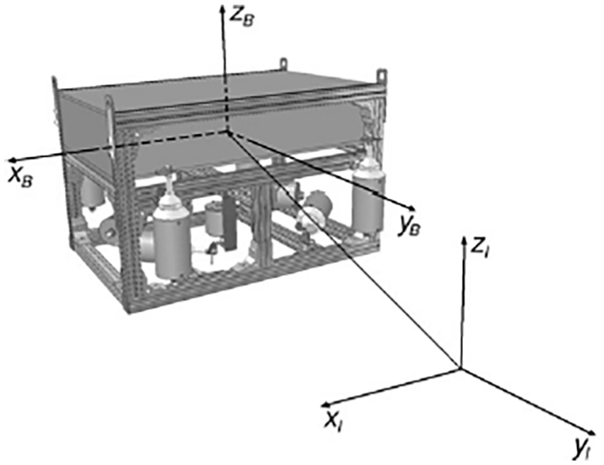
Underwater vehicle with both inertial and body-fixed reference frames. 29
Assumption 1
The parameter
Assumption 2
The parameter
Design of a new hybrid robust depth control with disturbance observer
In this section, an overview of the sliding mode controller for the described system in the previous section is presented. In addition, a new sliding mode controller and the proposed disturbance observer are designed.
An overview of SMC
Consider the nth order nonlinear dynamical system as

where
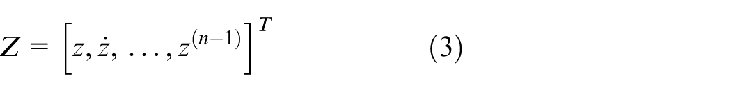
is the state vector, and u is the input vector. Suppose that

Let

where

here,
Assumption 3
The states z and
Assumption 4
Furthermore,
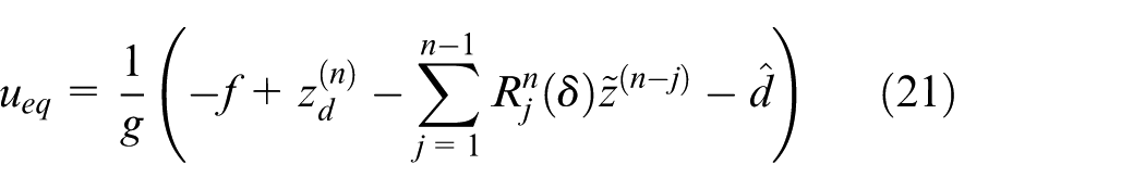
In most studies, remotely operated underwater vertical motion control problems are solved according to the SMC approach. In this method, the control law is composed of two components: the equivalent control term that is defined as
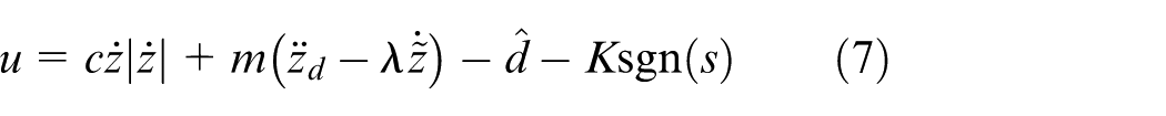
where
It can be easily verified that Equation (7) is sufficient to impose the sliding condition
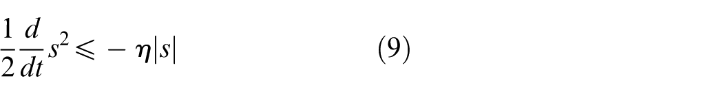
where
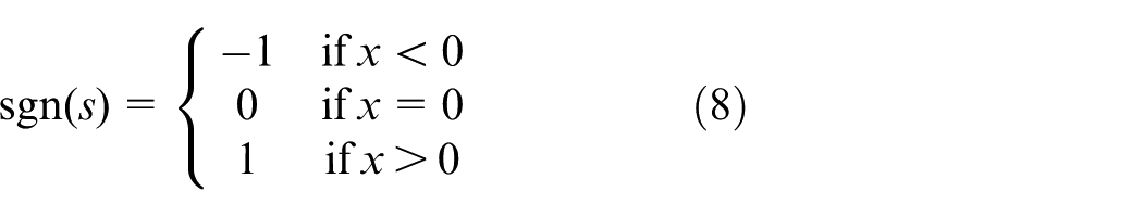
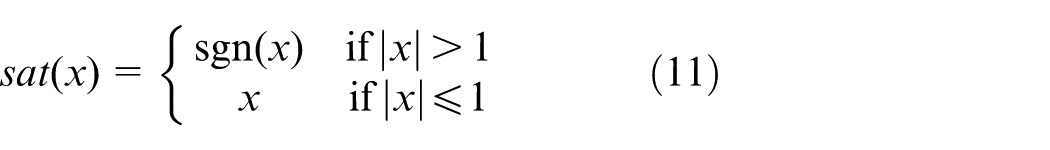
Pure sliding mode controller has some undesirable properties such as chattering and being too vulnerable against noise. The first problem, chattering, causes high-frequency oscillation in the controller output and the other is the sensitivity problem. This controller is very sensitive to noise when the input signals are very close to zero. 31 As shown in the “Simulation results,” section, in the presence of external disturbances, the controller has a good track but chattering may occur in the control input. One strategy to eliminate chattering is BLC in which the saturation function is used instead of sign function as follows
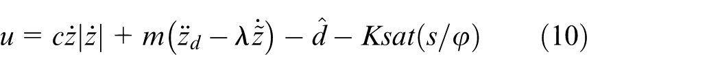
where
Time-variant SMC
A sliding function is defined as

and
A theorem for objectively choosing the coefficients of error states in sliding equation is presented as follows.
Theorem 1
If
We have
Proof
Refer to Yarahmadi et al. 24
Definition 1
Define the rejection regulator in the following form 24
where
Lemma 1
If

Proof
Refer to Yarahmadi et al. 24
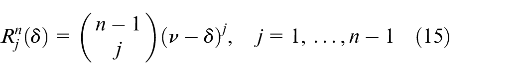
If we consider the sliding equation in the following form
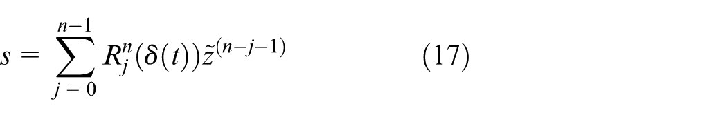
where
According to Lemma 1, we have
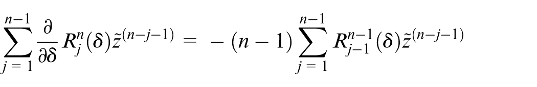
Therefore
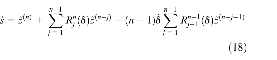
Substituting Equation (2) into Equation (18), we get
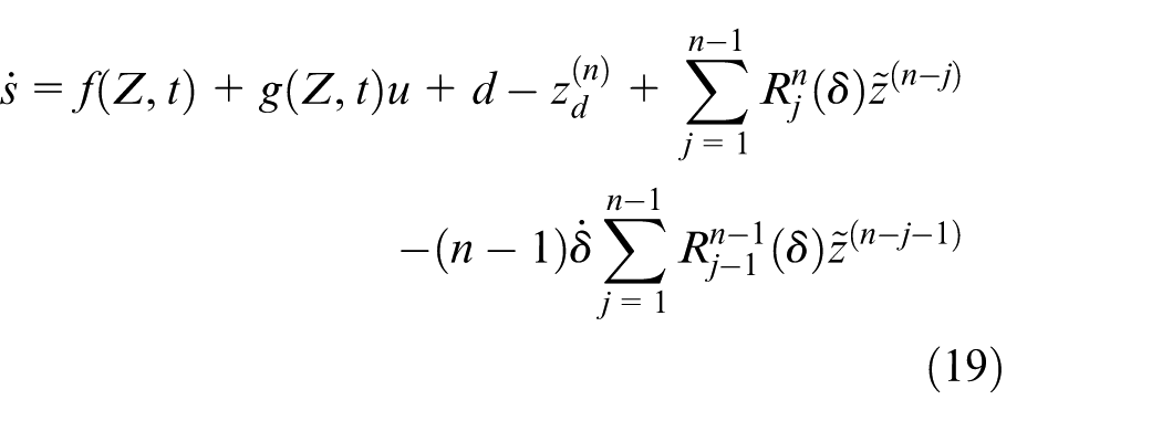
Then, we define

where
where
To estimate the unknown disturbance, Equation (1) can be written as

Then, the disturbance observer is defined as 22

where

which means that the disturbance varies slowly relative to observer dynamics.
In this paper, we assume that

where
Now, define the estimation error as

Substituting Equations (24) and (23) in Equation (26) yields
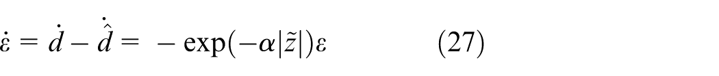
Therefore, the estimation error dynamic can be written as

which means that the observer is globally asymptotically stable and the exponential convergence rate is damped by
Theorem 2
Consider nonlinear system described by Equation (2) and sliding surface by Equation (17); if the robust sliding mode controller is designed as Equations (20) and (21) in which an adaption law as
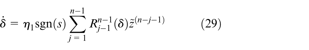
and a robust controller as
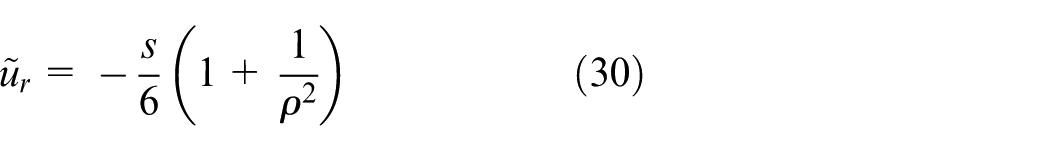
are defined, then the following properties are established:
The
If d is square-integrable, then
Proof
1. Consider the Lyapunov function in the following form
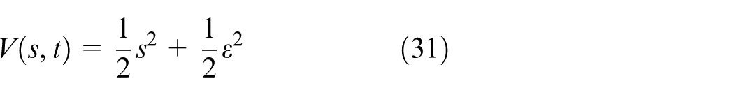
Differentiating equation (31), with respect to time, yields

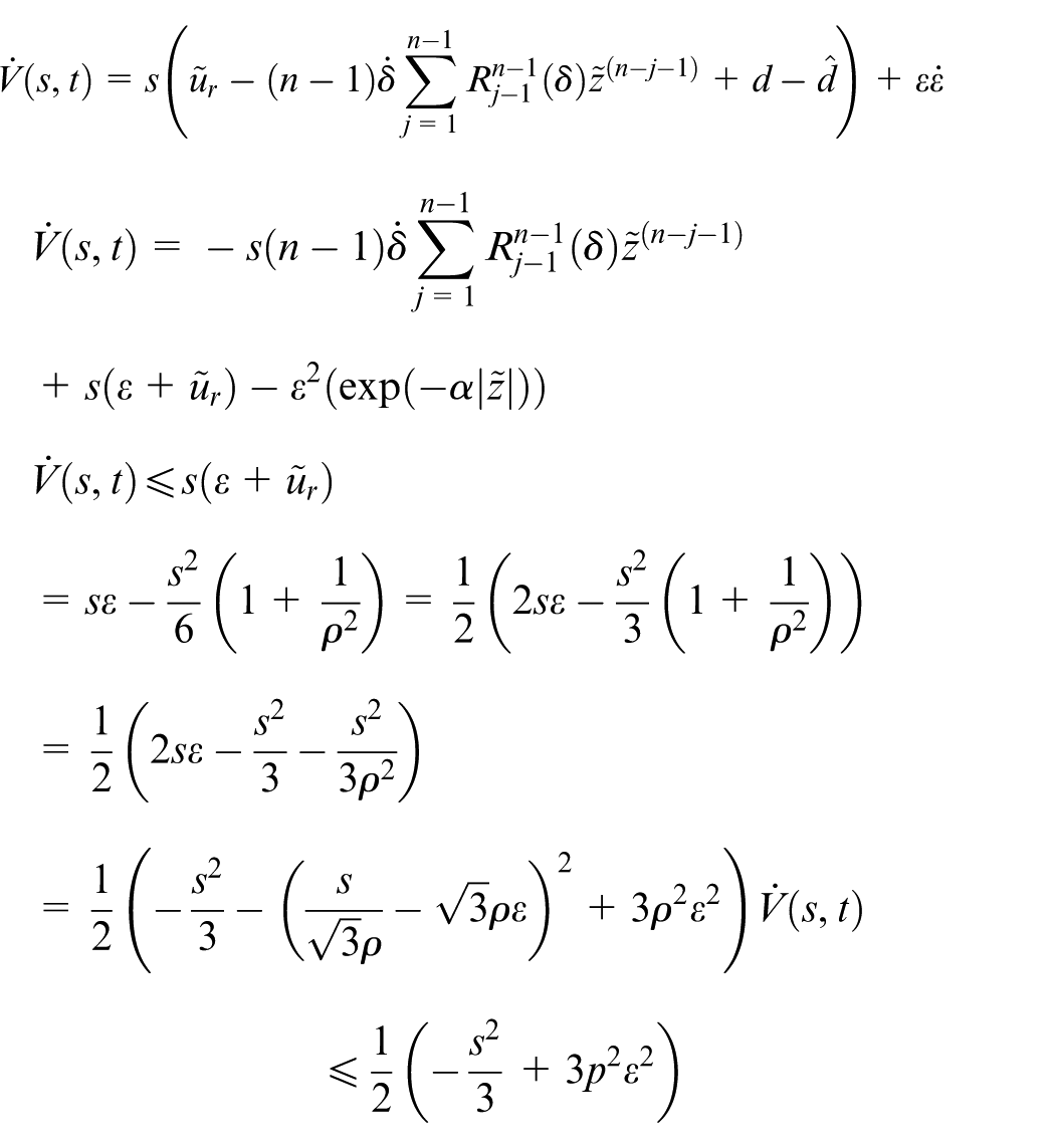
Then
As

where
2. Let
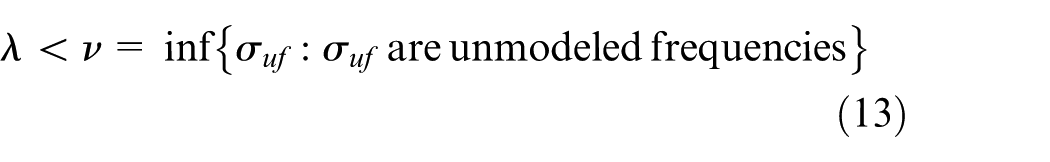
According to the proposed sliding surface and SMC laws in Theorem 2, the sliding surface, as a chain of adaptive low-pass filter, rejects all the unmolded frequencies and external disturbances. Also, the hybrid sliding mode and
Simulation results
Example 1
In this section, the performance of our proposed controller is compared with the sliding mode with BLC and STSMC in Ismail and Putranti.
28
Consider an AUV’s dynamical equation presented in Equation (1) with
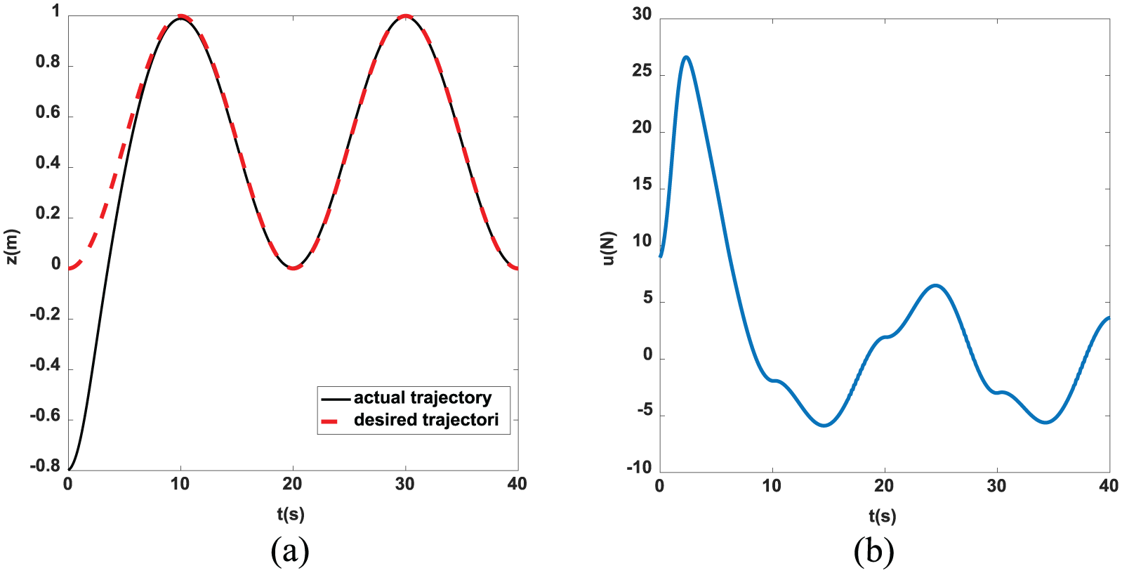
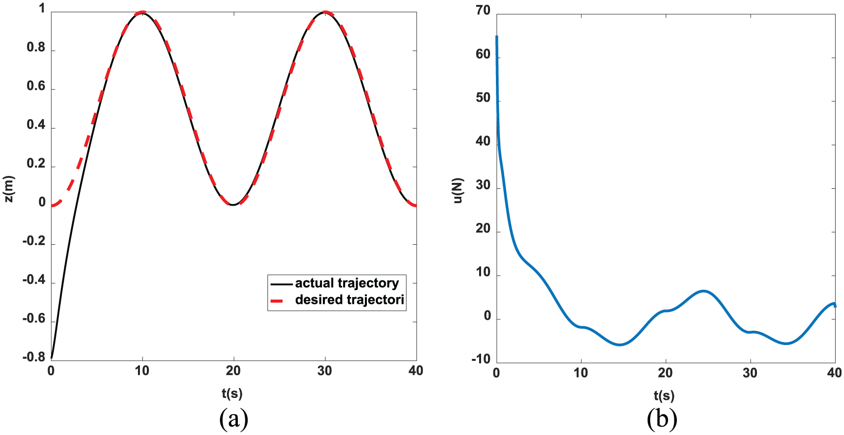
In Figures 2 and 3, tracking performance and control signal for the proposed controller for two different initial conditions, positive initial condition (PIC) and negative initial condition (NIC), are simulated. In addition, to reach a comparison situation, tracking performances and control signals of STSMC in Ismail and Putranti 28 and BLC methods are illustrated in Figures 4–7, for the two different initial conditions. Also, Figures 4 and 6 show the simulation results of tracking performance and control signal for PIC, and Figures 5 and 7 show the simulation results of NIC based on STSMC and BLC methods.
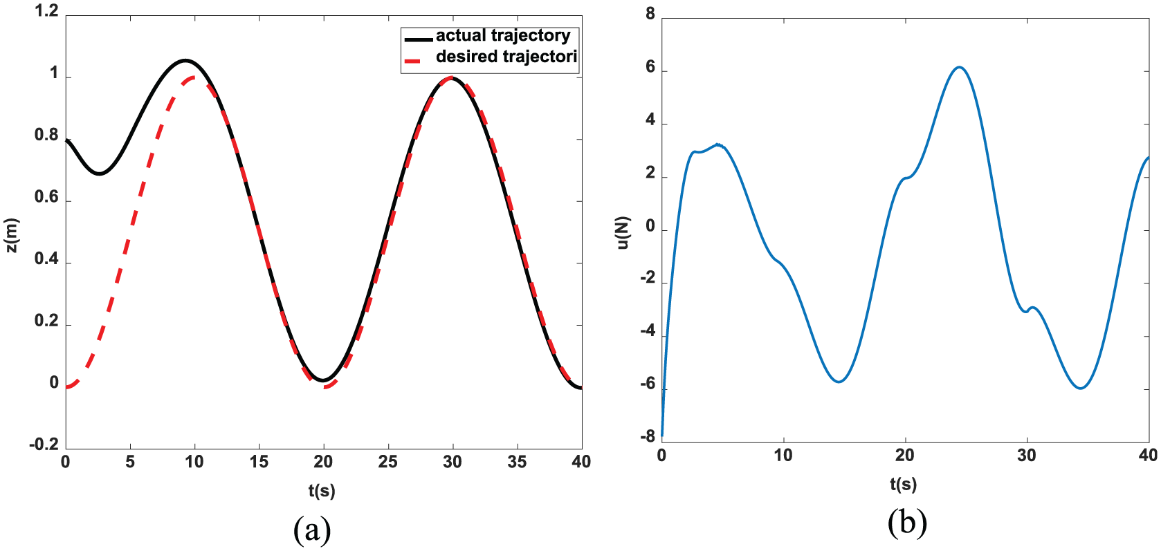
(a) Tracking performance with
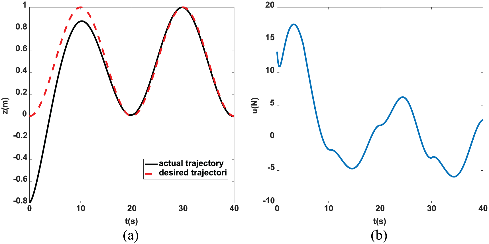
(a) Tracking performance with
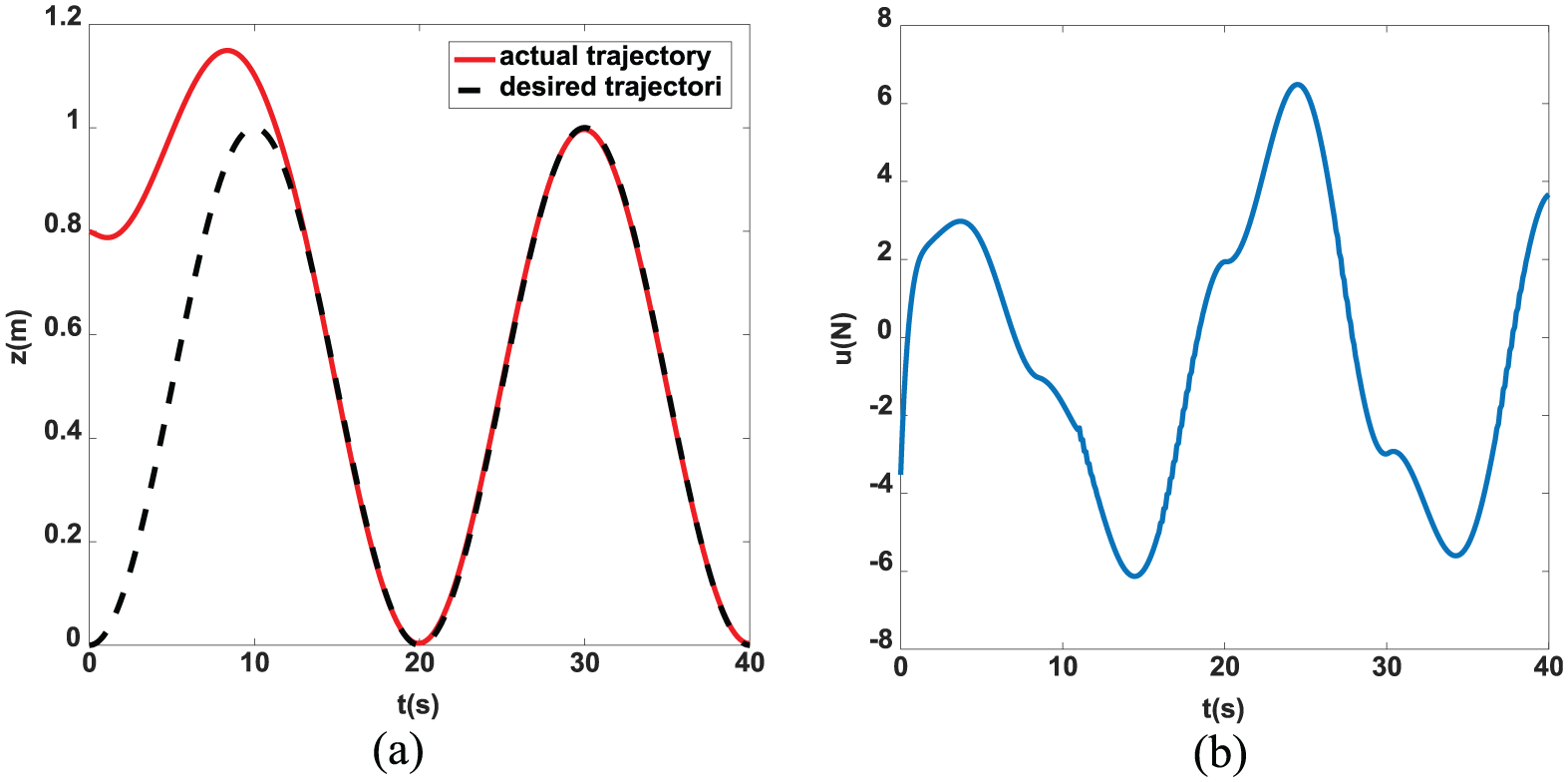
(a) Tracking performance with
(a) Tracking performance with
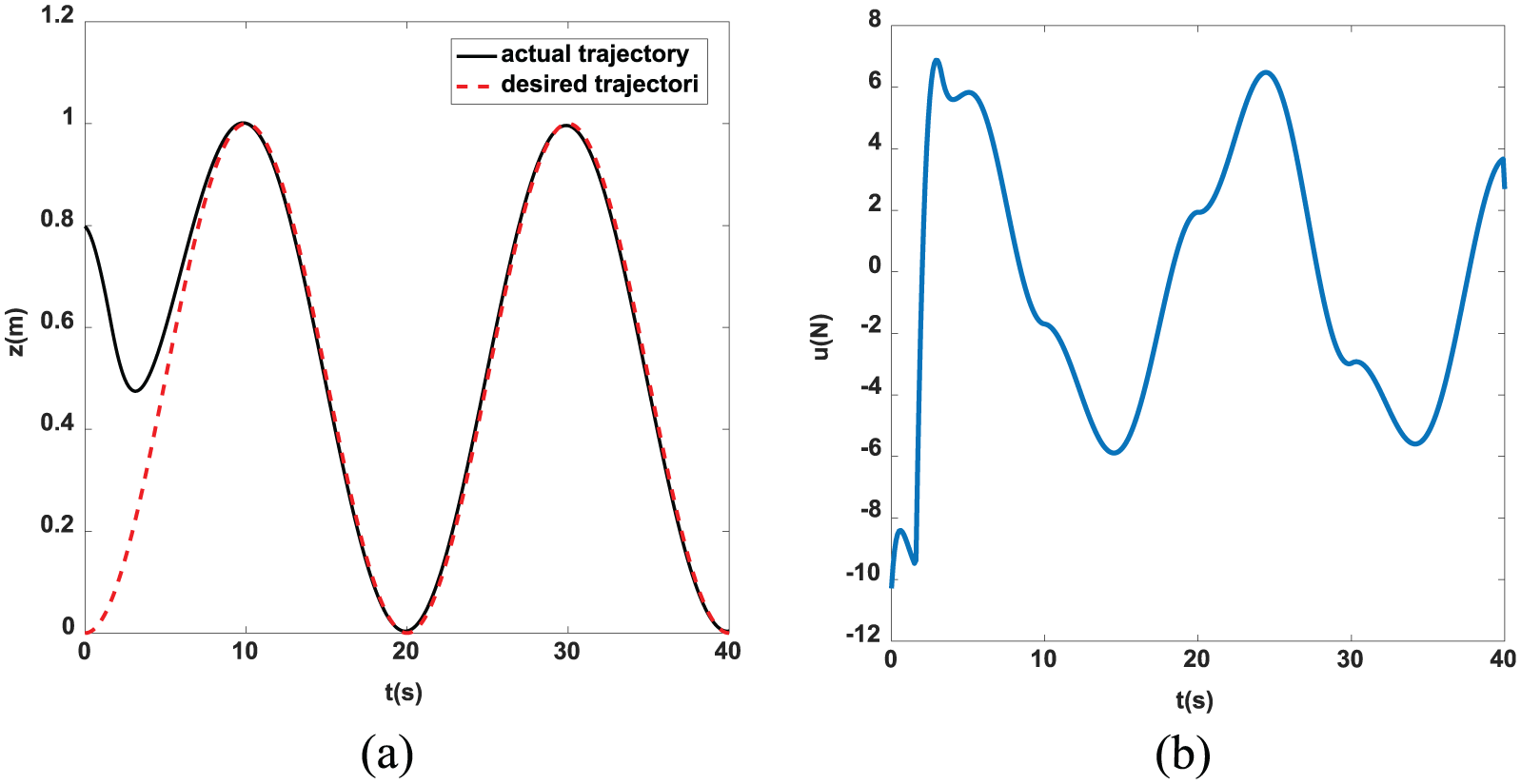
(a) Tracking performance with
(a) Tracking performance with
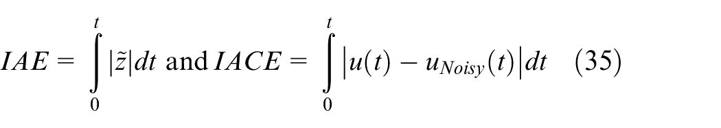
In these simulations, we use integral absolute control error (IACE) as a criterion for calculating the dispersion of the control signal against noise. Integral absolute error (IAE) and IACE are defined as
In Tables 1 and 2, the interval control effort (control amplitude), and IAE and IACE criteria are considered for comparing the control performances of BLC, STSMC, 28 and the proposed method without noise and in presence of noise, respectively. According to Table 1, the interval control efforts of the proposed method for two initial conditions are less than BLC and STSMC methods significantly. Also, the IAE performance index for proposed method is less than the index for STSMC and BLC methods.
Performance of three methods for two initial conditions without noise.
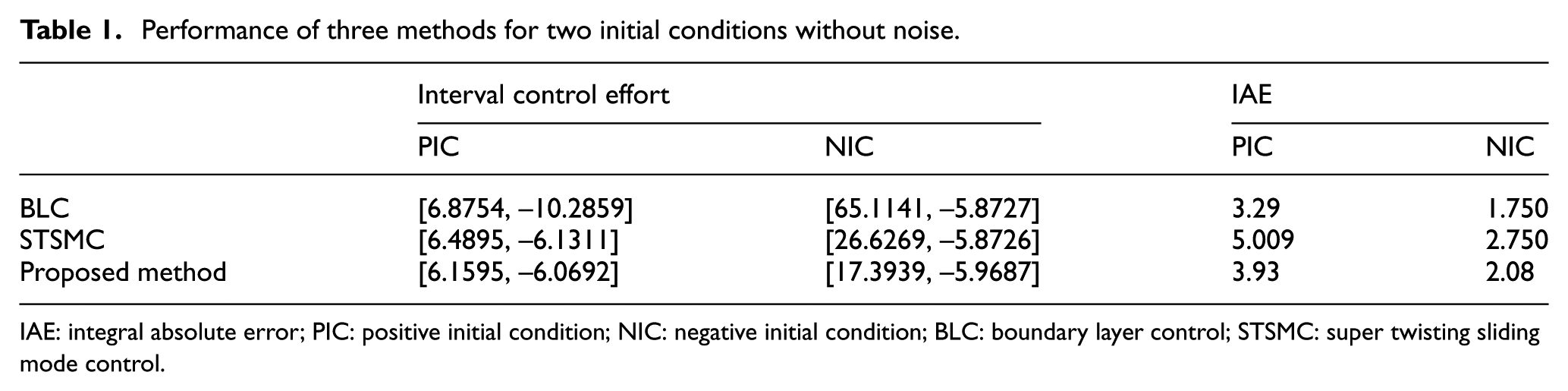
IAE: integral absolute error; PIC: positive initial condition; NIC: negative initial condition; BLC: boundary layer control; STSMC: super twisting sliding mode control.
Performance of three methods for two initial conditions in the presence of noise.
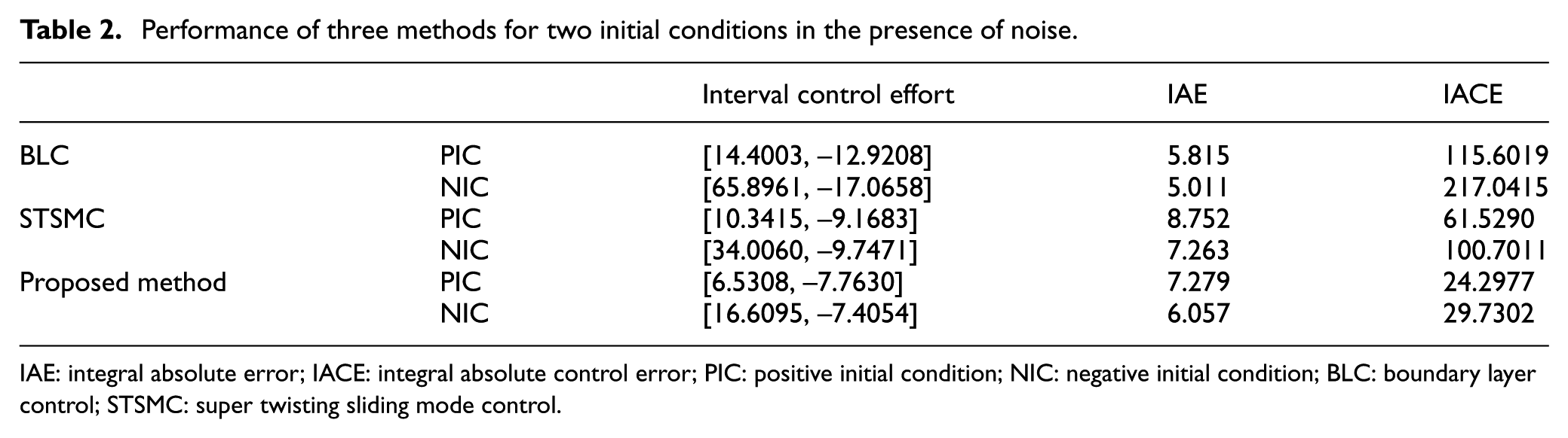
IAE: integral absolute error; IACE: integral absolute control error; PIC: positive initial condition; NIC: negative initial condition; BLC: boundary layer control; STSMC: super twisting sliding mode control.
Table 2 shows that the interval control efforts of the proposed method for NIC and PIC are less than BLC and STSMC methods in the presence of noise. By surveying Tables 1 and 2, it is inferred that IAE in BLC method is less than the other methods.
Finally, from Figure 8 and IACE performance index in Table 2, it can be seen that the proposed controller shows acceptable behavior against noise, but STSMC and BLC are vulnerable against noise and high chattering phenomenon occurred in STSMC and BLC methods. In addition, IACE performance index for the proposed method is very less than BLC and STSMC methods. Also, IAE performance index for the proposed method is very less than STSMC method. The proposed disturbance estimation is shown in Figure 9. It can be seen that the estimation in the proposed method is better than the other in Chen et al. 22
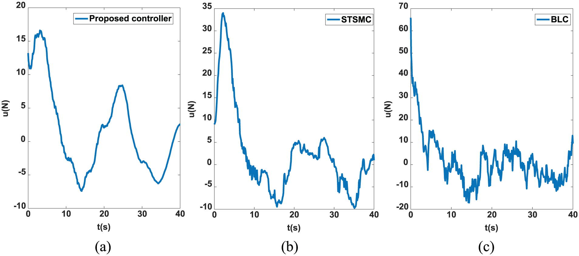
Control signals in the presence of noise: (a) proposed method, (b) STSMC method, and (c) BLC method.
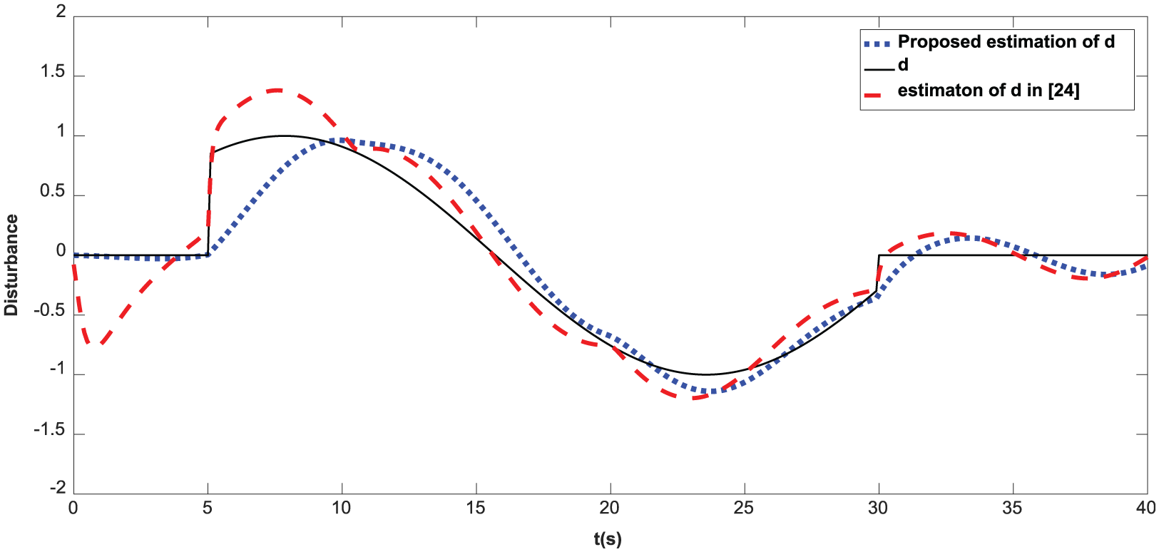
External disturbance and its estimation.
Example 2
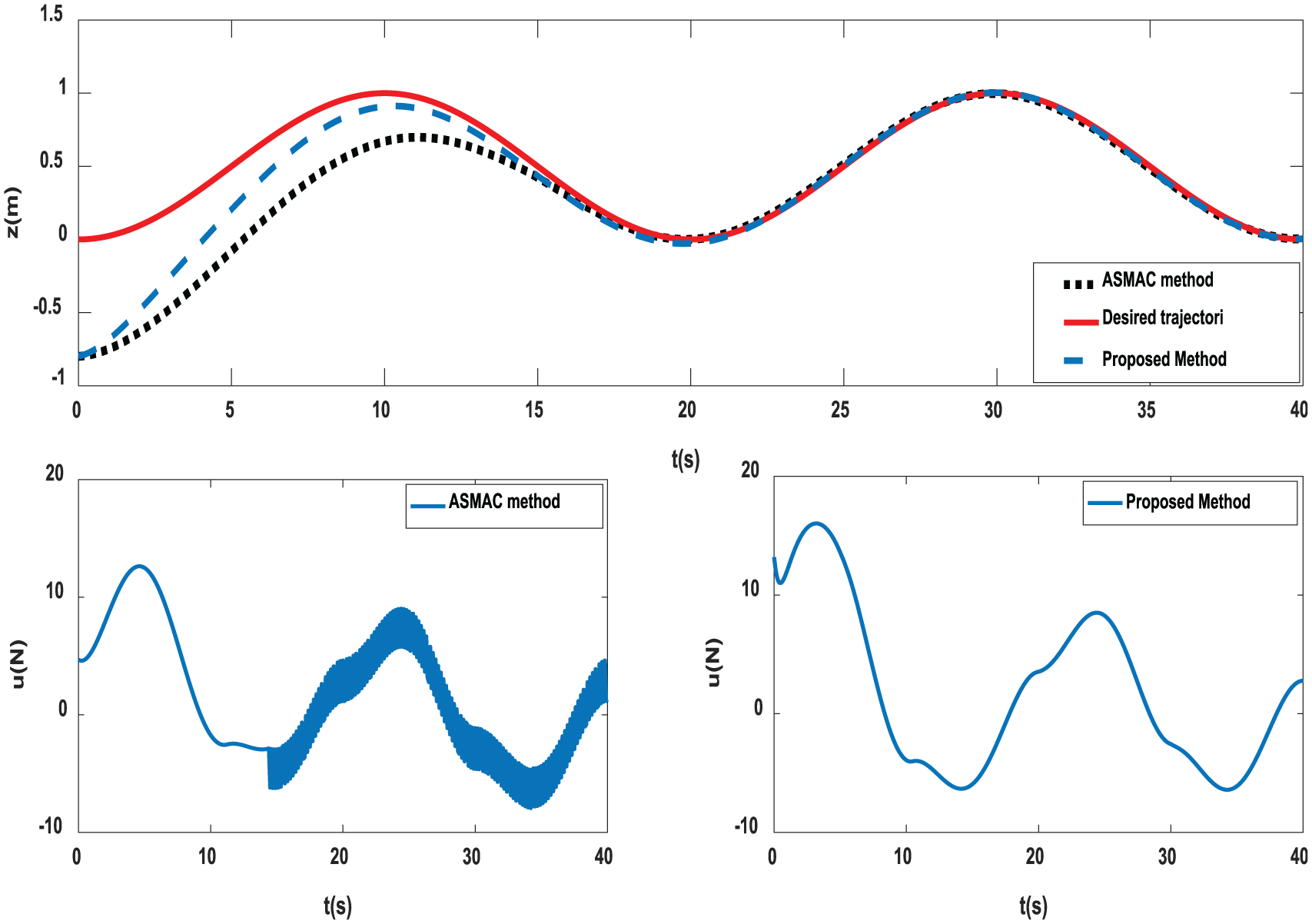
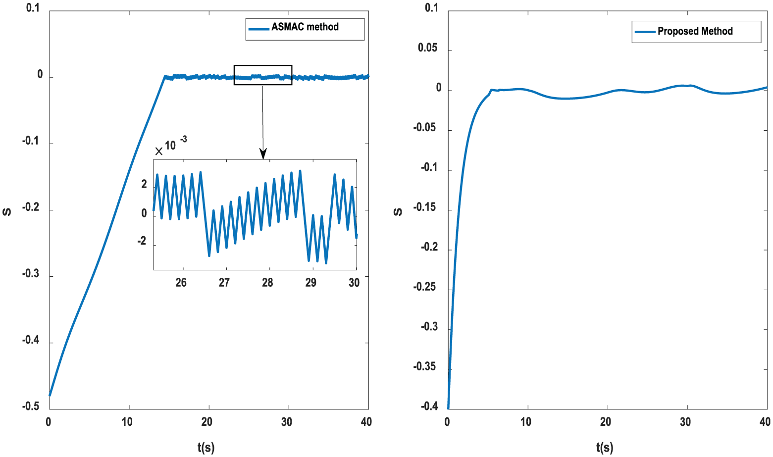
In order to show the efficiency of the proposed controller, the performance of the proposed method has been compared to the adaptive sliding mode attitude control (ASMAC) method in Cui and Zhang. 27 For this purpose, the presented system in this paper is simulated based on the presented method in Cui and Zhang 27 in the following cases:
Case 1: If the constant gains of the controller are selected as
Case 2: In this case, we try to select the constant gains
However, it can be seen that the control signal in the proposed method does not have any chattering with the less reaching time in comparison with the method in Cui and Zhang 27 for two cases.
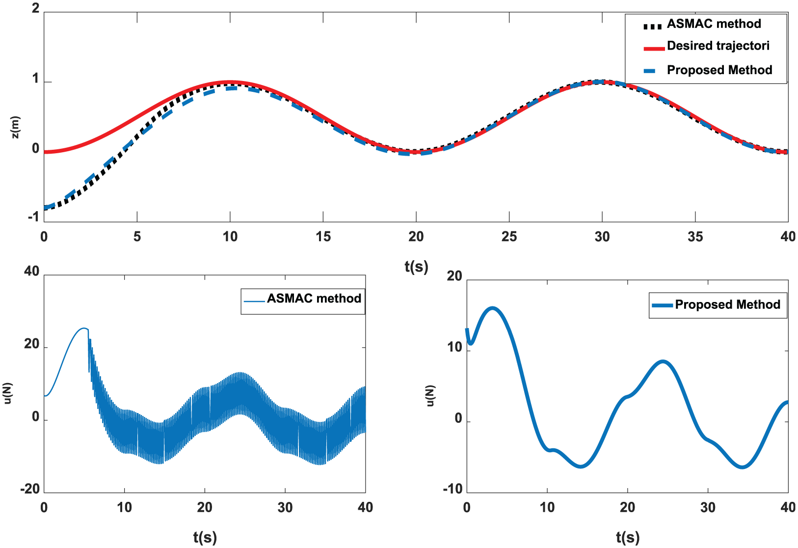
Tracking performance and control signal using ASMAC and presented methods, for Case 1.
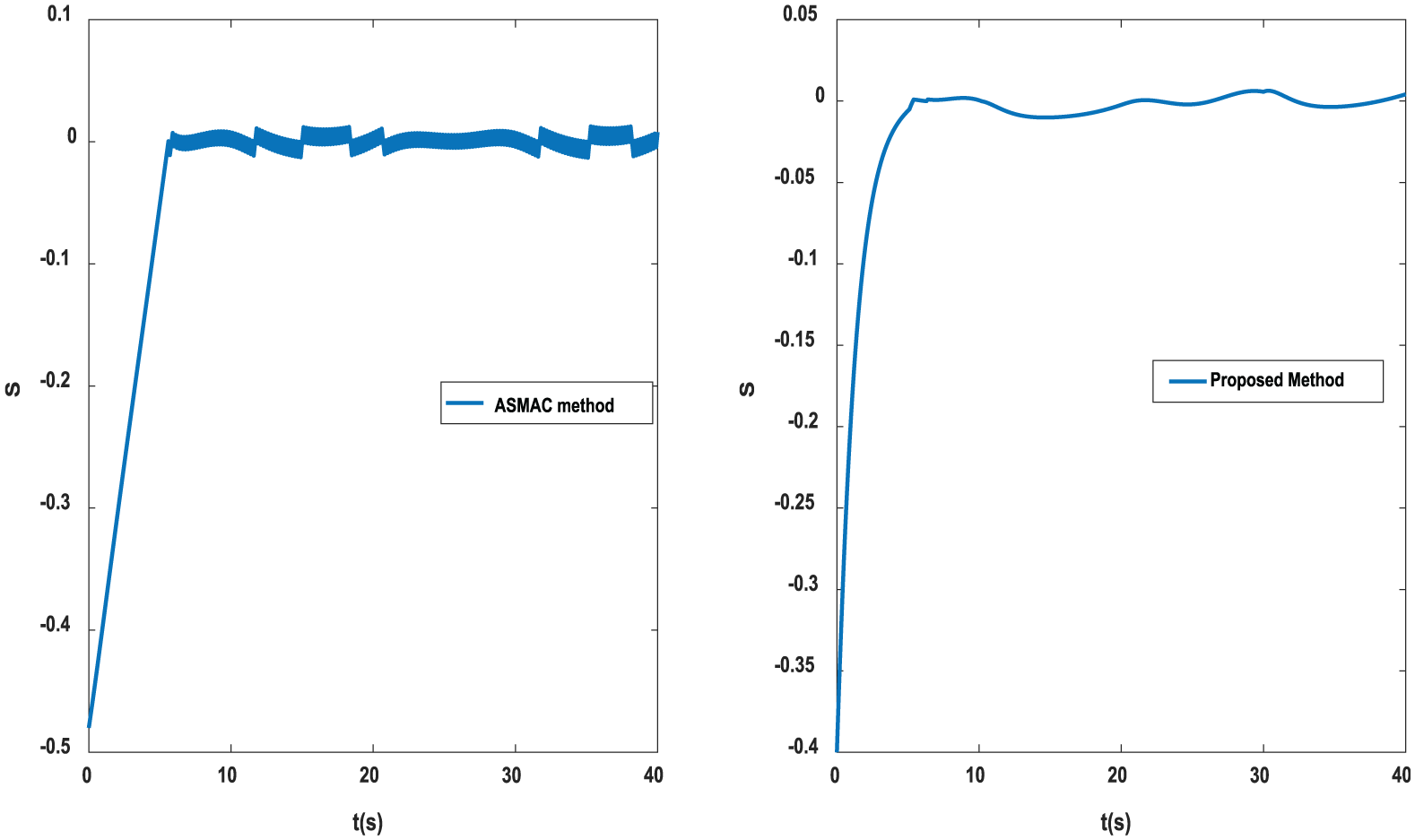
Sliding surface using ASMAC and presented methods, for Case 1.
Tracking performance and control signal using ASMAC and proposed methods, for Case 2.
Sliding surface using ASMAC and proposed methods, for Case 2.
Conclusion
In this paper, a new hybrid robust tracking control for an underwater vehicle in dive plane via
Footnotes
Declaration of conflicting interests
The author(s) declared no potential conflicts of interest with respect to the research, authorship, and/or publication of this article.
Funding
The author(s) received no financial support for the research, authorship, and/or publication of this article.