
Abstract
In view of the strict requirements of the current high-precision measurement system for stable output power of the semiconductor LD (Laser Diode), a semiconductor LD stable power drive and multi-closed-loop control system are proposed after analyzing the semiconductor laser’s P–I (Power–Current) characteristics and temperature characteristics. The system uses a microcontroller as the core control unit and realizes the stable power output control of the semiconductor laser by controlling the current, power and temperature parameters. In this system, first, the control structure model of the controlled object has been designed. Second, a controllable closed-loop constant current feedback drive circuit has been designed and a high-precision controllable constant current drive circuit of the semiconductor laser has been obtained. Furthermore, the control circuit has been designed based on the neural PI (Proportional-Integral) control model and realizes the short-term stable power output of the semiconductor LD. Finally, a closed-loop temperature control system is designed to ensure that the operating temperature of the semiconductor laser is relatively stable and a long-term stable power output is obtained. By designing the hardware and software of the control system and conducting long-term experiments in the laboratory, we found that the system can guarantee the output power within 1 W of PD (Proportional-Differential) LD, and its long-term power stability can reach 1%. This system has a certain reference significance in using semiconductor lasers for high-quality detection when there are stringent requirements for power.
Keywords
Introduction
Due to their many advantages, such as high efficiency, small size, light weight, high reliability and direct modulation capability, semiconductor lasers have been widely used in many fields, such as material detection, environmental monitoring, component analysis and optical storage.1,2 In a high-precision detection system, there are strict requirements for the semiconductor laser’s output optical power, center wavelength and the spectral characteristics, and minor variations of these will affect the accuracy of the detection results.3–5 The semiconductor laser is a device with high power density and extremely high quantum efficiency. At the same time, it is a relatively sensitive device. According to the working principle and basic electrical characteristics of the semiconductor laser,6,7 it is known that the small changes of the current that is injected into the semiconductor laser and of the operating temperature can both cause remarkable changes in the device’s output optical power, center wavelength and spectral characteristics.8,9 For example, a change of the current of a certain type of laser will cause a drift of the output wavelength of about 0.01 nm/mA. A change of temperature will cause a change of the output wavelength of 0.1 nm/°C. These changes directly jeopardize its performance and safety.10,11 Therefore, the driving current and the operating temperature are key factors that determine the work performance of the semiconductor laser. Therefore, the key steps in the design of the semiconductor laser driving circuit with high-precision stable power output are the injection of current, temperature control and power stable control.
Since the advent of automatic semiconductor lasers, the design of their driving and control circuits has always been the focus of attention. Researchers at home and abroad have also conducted extensive research on this and achieved certain results. At present, lasers with drive currents of tens to hundreds of amperes have been designed abroad. 12 The US company Wavelength Electronics 13 is a technology leader in the field of semiconductor lasers driving in foreign countries. There are many products in the laser driving field, such as the LDTC2/2E, whose maximum current can reach 2.2 A, the microwave is 50 ppm of 24 h constant current driving and the temperature stability can reach one thousandth of a degree. The US Company ILX Lightwave 14 provides a laser driver, temperature controller and fixture device. The company’s desktop laser driver can provide continuous adjustable or pulsed drive current from 100 mA to 6 A, which can effectively ensure the output of the laser stabilization wavelength. The LPS1-2T 15 series of semiconductor laser drivers produced by the German company ALPHALAS can reach the highest 100 A of driving capacity. Its temperature control accuracy is 0.001° and it also includes a good protection alarm device. The AVTECH multinational company is famous for specializing in the production of miniaturized high-speed pulse sources and the model of its production is AVOZ-AIA-B and AV1011-B of drive power supply. The electric pulse peak can reach 2 A, the pulse width is 100 ns, the pulse rise time is only 10 ns and the repeat frequency can reach 1 MHz. The dynamic power supply pulse width is less than 50 ns, the repeat frequency is 1 MHz and the peak current is 12 A, in DEI company’s PCO-7210. The IC-W series semiconductor laser control chip developed by Germany’s IC-Haus company pays attention to the integration of the unit circuit.16,17 A large number of circuits are integrated in a small chip, with ripple cancelation, soft start and stable output current and can be modulated by external signals, also achieving other functions. 18 Italian researchers have changed the injection current of the laser by detecting the change of photocurrent of the photocell until the output power is stable at the set value. 19 In Japan, the method proposed by Yamaguchi et al. is that the characteristics of the output laser are obtained by measuring the phase offset, then fed back to the computer and processed, thereby further changing the injection current of the laser and achieving modulation of the laser.20,21 In the United Kingdom, Hancock et al. 22 also proposed a similar method, where the CCD (Charge-Coupled Device) and sinusoidal phase modulation are used to modulate the input current of the semiconductor laser, so that the modulated laser signal has higher accuracy. The method of using photothermal to modulate the semiconductor laser has also been the subject of early research in the United States and Japan.23,24 Takamasa et al. studied temperature control for semiconductor lasers using other lasers. The laser which is the output of CCD collection, the interferometer and the method of sinusoidal phase modulation are used to adjust the laser’s operating temperature, thereby achieving highly accurate modulation of the output of the semiconductor laser. 25
Characteristics of semiconductor lasers
Semiconductor lasers work by subjoining the energizing working medium additionally. The working medium is a PN junction or a PIN junction. The temperature has a great influence on the PN junction, 26 and the semiconductor laser’s threshold characteristics and output power wavelength can both be affected by changes of temperature. At the same time, the stability of the laser output power depends on the stability of the semiconductor laser injection current, so it is necessary to analyze both its P–I characteristics and temperature characteristics.
P–I/U–I characteristics
The P–I characteristic is shown in Figure 1(a). The characteristic curve shows the correlation between the output optical power P and the injection current value I. When the current on the LD increases, the optical power also increases slowly. When the current on the LD reaches a certain value, the optical power increases sharply and the LD emits laser light. The current at this moment is the threshold current and is marked as
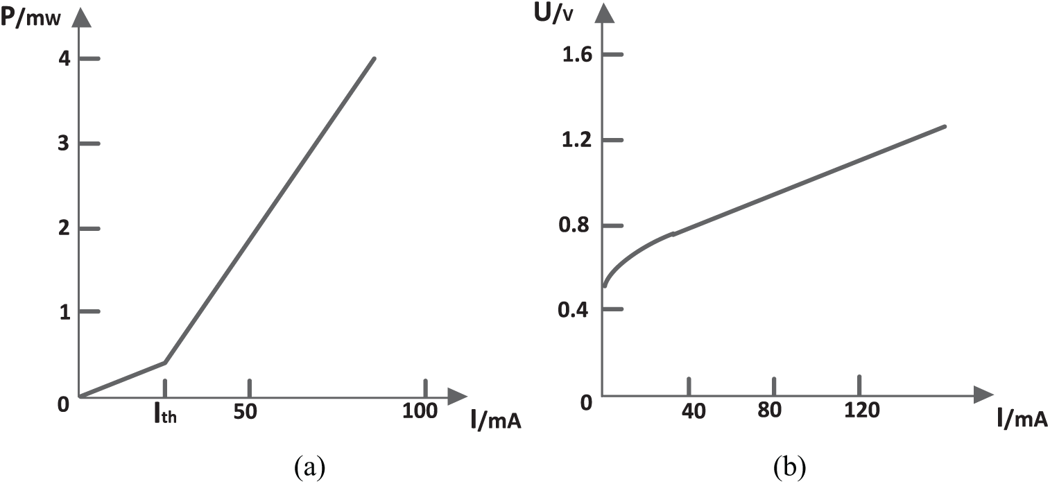
P–I/U–I characteristic curve: (a) P–I curve and (b) U–I curve.
Temperature characteristics
Because the LD is a thermal power device, as its operating time increases, the temperature of the PN junction also rises. At the same time, as an electron–photon conversion device, the LD cannot convert 100% of the electrical energy into light energy. Part of the electrical energy will be converted to heat and this will cause the temperature of the LD to rise sharply.27,28 The temperature change will have a great impact on various performance indicators of the LD, such as the size of the output optical power, the output wavelength, the size of the threshold current and a series of other indicators.29,30 Figure 2 reflects the changes of optical power in the wake of a change of injection current at different temperatures.
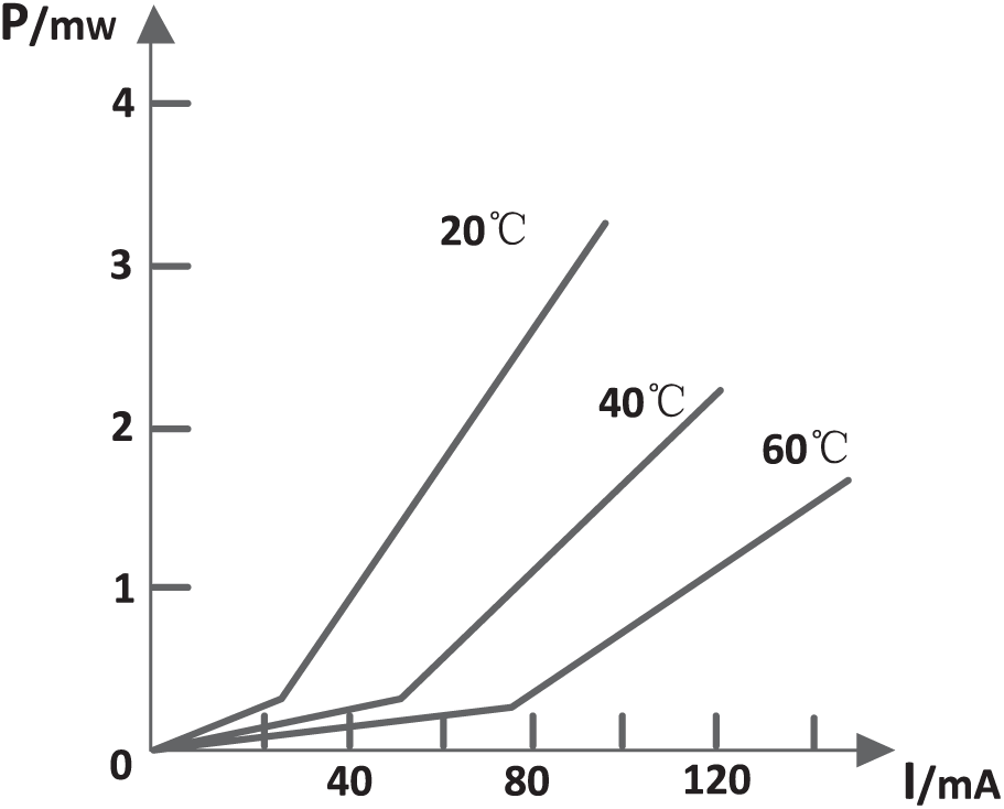
Temperature characteristic curve.
It can be seen from Figure 2 that: (1) With the rise in temperature, the abscissa which is corresponding to the inflection point of the P–I curve gradually shifts to the right, that is, the threshold current of the LD gradually increases. This shows that when the temperature is higher, only a bigger current is injected can be successfully drive the LD. (2) When the temperature is constant and the injection current of the LD is greater than the threshold current, the output optical power P and the injection current value I have a linear relationship. That is, the output optical power of the LD increases as the injection current increases. When the injection current of the LD is greater than the threshold current, the slope of the P–I characteristic curve decreases as the temperature increases; in the case that the injection current is the same, the higher the temperature, the lower the output optical power of the LD.
Overall scheme of stable power drive of semiconductor lasers
It can be seen from the above analysis that in a constant temperature environment, as long as the injection current of the laser is well controlled, the output power of the laser can also be conveniently controlled. Therefore, the output optical power of the laser can be accurately detected by detecting the photocurrent, and then under a constant temperature environment, its injection current is adjusted to achieve the stable power drive of the semiconductor laser.
Three closed-loop table power model design of laser
The block diagram of the principle of the LD stable power drive is shown in Figure 3. It is a negative feedback and double closed-loop control system, which consists of input quantity, output quantity, controlled object and measuring components and so on. The output quantity is the optical power of the LD. The constant power drive circuit of the LD includes three negative feedbacks. The internal negative feedback is the current loop and the current signal is used as the amount of feedback. Eventually, it reaches a state of dynamic balance of negative feedback and achieves a stable output of optical power.
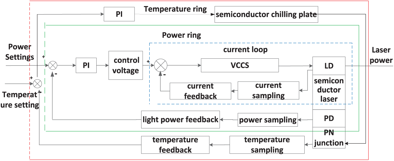
Block diagram of stable power drive.
After sampling and amplifying, the size of the injection current of the semiconductor laser is determined jointly by the current signal and the control voltage. The current loop can minimize the current deviation to the utmost extent. It can effectively reduce the errors caused by internal and external factors and maintain the stability of the injection current. The external negative feedback control system is the power loop, that is, the optical power of the LD is used as the feedback signal. The power signal’s collection converts the optical signal into an electrical signal using the photodiode, and then feeds it back to the input through sampling, amplifying and other links, and controls the output optical power of the LD. The outermost is the temperature loop and by collecting the temperature signal of the PN junction, the control signal of the output, which after the temperature deviation is passed through the PI regulator, is calculated. The semiconductor cooling sheet is controlled to adjust the temperature of the PN junction and make it constant. This multi-closed-loop negative feedback control system has greater stability and an anti-interference capability; that is, the LD injection current is more stable and the output optical power accuracy is higher.
Hardware design scheme of lasers constant power drive
According to the above functions to be realized and the corresponding LD constant power drive performance index, the overall block diagram of the LD constant power control hardware is designed as shown in Figure 4. The current loop directly selects the high-precision controlled constant current source chip LT3080 which has a closed-loop design. The maximum output current is 1.1 A and its interior has the high-precision reference current source. The microcontroller can digitally adjust its output current via the conversion circuit and the minimum adjustment accuracy is 0.5 mA. The power detection circuit of the power loop detects the power change of the semiconductor laser by the PD (Proportion-Differential) terminal and converts it to a digital signal by the A/D (Analog/Digital) conversion circuit. The temperature loop includes the temperature detection circuit, the refrigeration drive circuit and the fan drive circuit; a PWM (Pulse Width Modulation) drive is used in this part to digitally adjust its output.
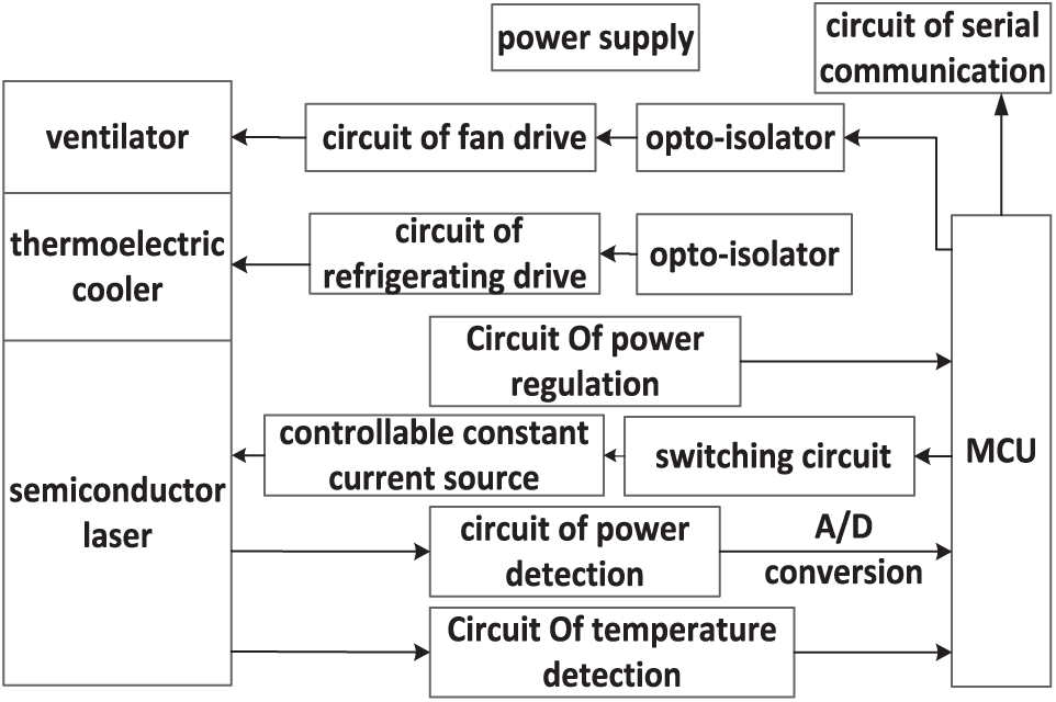
Overall block diagram of the LD constant power control hardware.
Structural model of laser’s controlled object
The controlled object is the semiconductor laser and its fixed device. A sectional view of its structural model is shown in Figure 5. It mainly includes the optical system, the heat-conducting housing, the laser tube, the constant temperature chamber, the thermoelectric cooler (TEC) and the heat-conducting plate components, the heat-dissipating fin,31,32 the heat-dissipating fan and other parts. The laser, the heat-conducting housing and the constant temperature chamber are filled with a heat-conducting material. The TEC is fixed on one side of the heat-conducting copper plate and the heat-dissipating fin is fixed on the other side. A heat-dissipating fan is mounted on the top of the heat-dissipating fin, 33 and the object can be equivalent to a time-delay nonlinear system with large inertia.
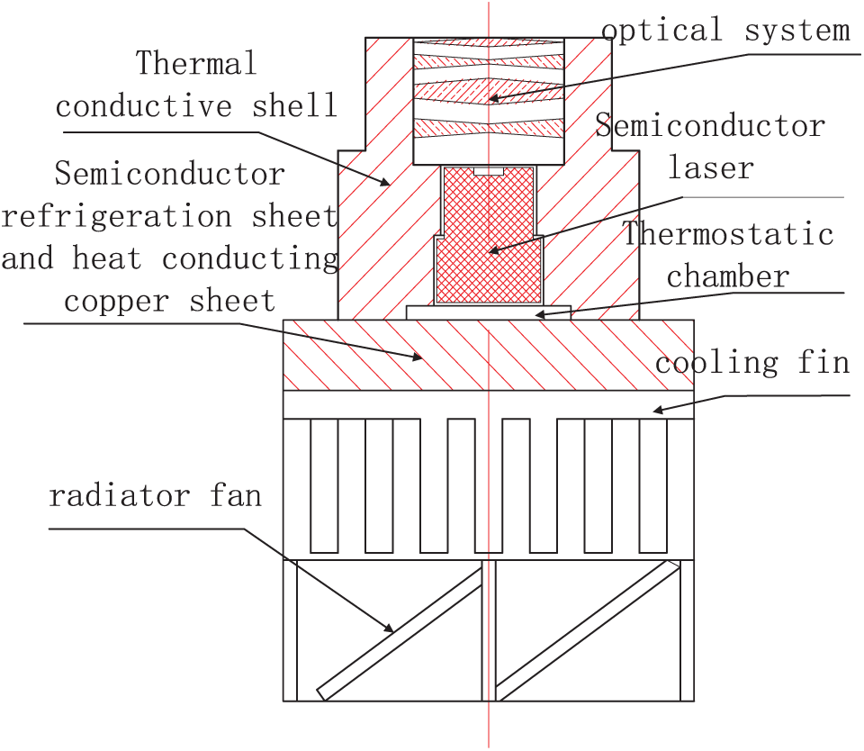
Sectional view of structure model of semiconductor LD and its fixed device
Stable power drive circuit of semiconductor lasers
Current loop
The constant power drive of the LD is a double closed-loop control system. Its inner loop is the current loop, that is, the constant current control. The constant current design is shown in Figure 6. The current loop is a constant current control system, which is composed of input quantity, output quantity, controlled object, measuring element and so on.
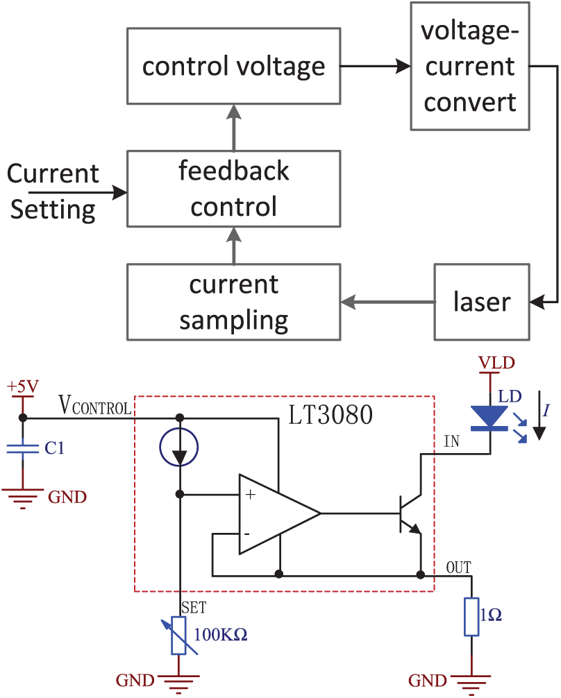
Operating principle of the current loop.
In Figure 6, LD represents the laser diode. The sampling resistor R of the LD is a precision resistor of 1 Ω. The current signal is converted into the voltage by the output current limiting resistor. It is fed back to the ‘SET’ terminal through regulating the potentiometer by the output current and it can allow the output current to be adjustable. The LT3080 requires only a small feedback resistor to achieve a constant current source with excellent performance and according to the voltage change of the constant current source on the
The output quantity of the current loop is the injection current of the LD. The laser diode is taken as the controlled object, the precision resistor, in series with the laser diode, is sampled to control the current size which is injected into the laser diode, and eventually a dynamic equilibrium state of negative feedback is reached, realizing accurate control of the LD’s current and stable output. Digital regulation of the output current can be achieved by adjusting the resistance.
Power loop
The power loop is a negative feedback control circuit that detects and feeds back the LD output optical power through the photodiode, which is packaged in the LD interior. 34 The power loop is the outer loop and is the constant power control system, which is composed of input quantity, output quantity, the controlled object, the measuring element and so on. Its input quantity is the set power, and it is converted through the microcontroller into a digital signal, and the signal is provided by the digital potentiometer. The controlled object is the LD control voltage (potentiometer resistance). After further adjusting and stabilizing for the injection current through the current loop, the output quantity, that is, the optical power, can be obtained. The precision resistor, in series with the photodiode, will form a feedback quantity after sampling for the optical power. The feedback quantity is processed by the amplifying circuit and fed back from the A/D port to the input terminal; it determines the control voltage with the presented power together.
Analysis of power loop principle
Figure 7 shows the simplified circuit of the power loop. As shown in Figure 7, the photodiode converts the optical signal reflected by the LD resonant cavity into an electrical signal, that is, the photocurrent IPD. After being sampled by the high-precision sampling resistor, the voltage signal, which is positive proportional to the output optical power, is obtained. After processing the voltage signal, it is compared with the preset value to adjust the control voltage of the current loop, and then the injection current of the laser diode is regulated further to maintain the stability of the optical power.
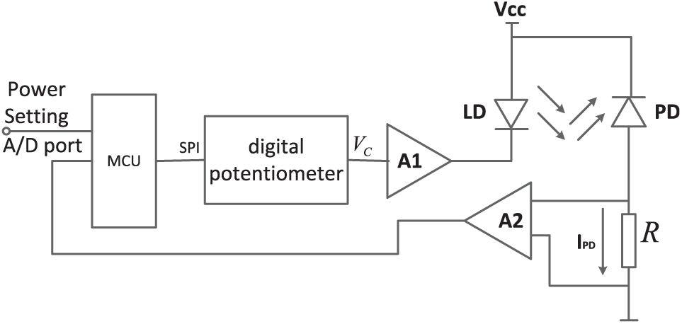
Control principle of power loop.
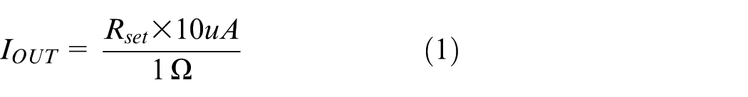
According to the performance index of the LD constant power drive circuit, the relationship between the injection current

where

From equations (2) and (3), the relationship between the injection current

where

where

Through repeatedly conducting experimental tests (controlling the injection current of the laser diode and observing the corresponding current generated by the photodetector tube),
Power loop circuit
In Figure 8, PD represents the photodiode, the sampling resistor of PD (
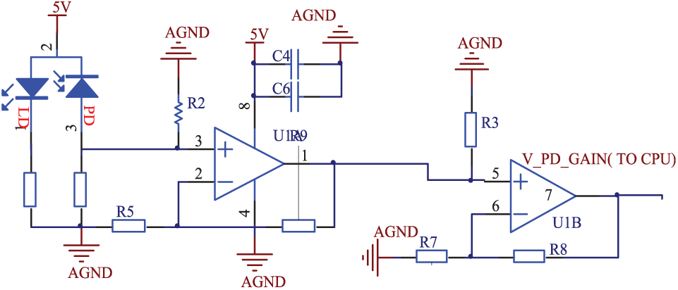
Circuit schematic diagram of power loop.
Temperature loop
The temperature loop is an important circuit to ensure the normal operation of the system. The temperature control circuit in this design is a separate closed-loop control system. The loop mainly includes the temperature detection circuit, the semiconductor refrigeration, the fan drive circuit, the optocoupler isolation circuit, the power conversion circuit and so on. Part of the peripheral circuit is shown in Figure 9. The 12 V stabilized voltage supply is used for refrigerating and the temperature control system is also the negative feedback circuit. The circuit realizes the isolation between digital and analog signals and it can prevent signal interference to a great extent. Further aspects of the temperature control parts are not discussed in detail here. 35
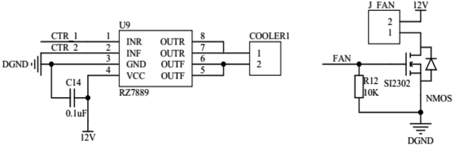
The refrigeration, fan drive circuit.
The implementation of the control algorithm
A PI controller is often used in the feedback control system. The traditional PI control method is simple in structure and easy to implement. It can meet the needs of most designs, but the ordinary PI control algorithm cannot meet the requirements of a system for which the accuracy is required is higher. 36 Meanwhile, the neural network algorithm has a self-learning ability and can infinitely approaching a nonlinear function. Therefore, in order to improve the stability of the LD output optical power, we adopt a control method combining a back propagation (BP) neural network algorithm35,36 and a PI algorithm to achieve a stable output of power. 37 The structure of the LD constant power PI control system based on the BP neural network is shown in Figure 10.
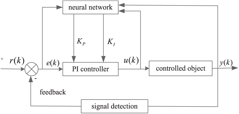
Block diagram of BP neural network PI control algorithm.
The incremental PI algorithm is shown in equation (7), where
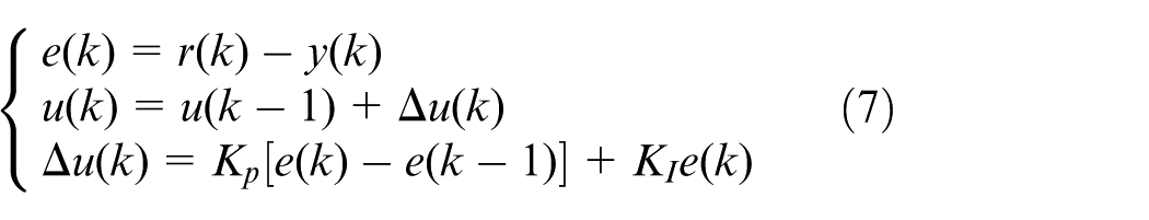
When

In order to verify the control effect of the BP neural network PI algorithm, a MATLAB simulation experiment was conducted. First, the LD mathematical model of power feedback control is established. The stable state relationship of each link can be obtained by the previous analysis, as follows.
The relationship between the injection current
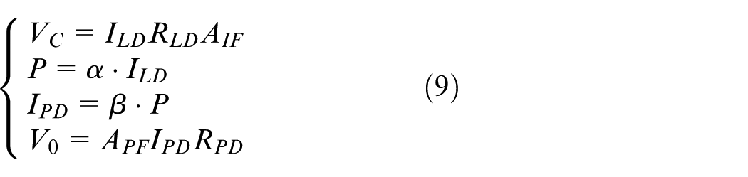
The link of voltage comparison

Neural PI algorithm controller
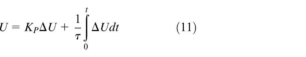
From the above formula, it can be obtained that the block diagram of the LD power feedback system structure can be obtained, as shown in Figure 11.
Block diagram of LD power feedback system structure.
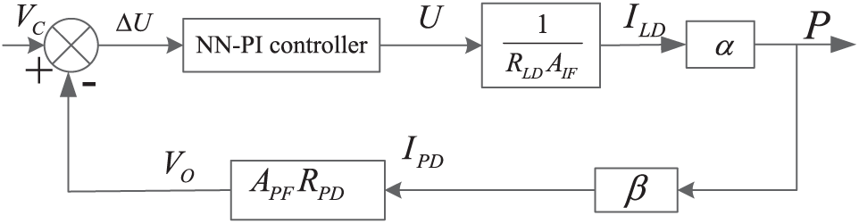
Using MATLAB to simulate the constant power control system of the lasers, the BP neural network PI algorithm is set as follows: the structure of the neural network selects 3-5-2, the learning rate is
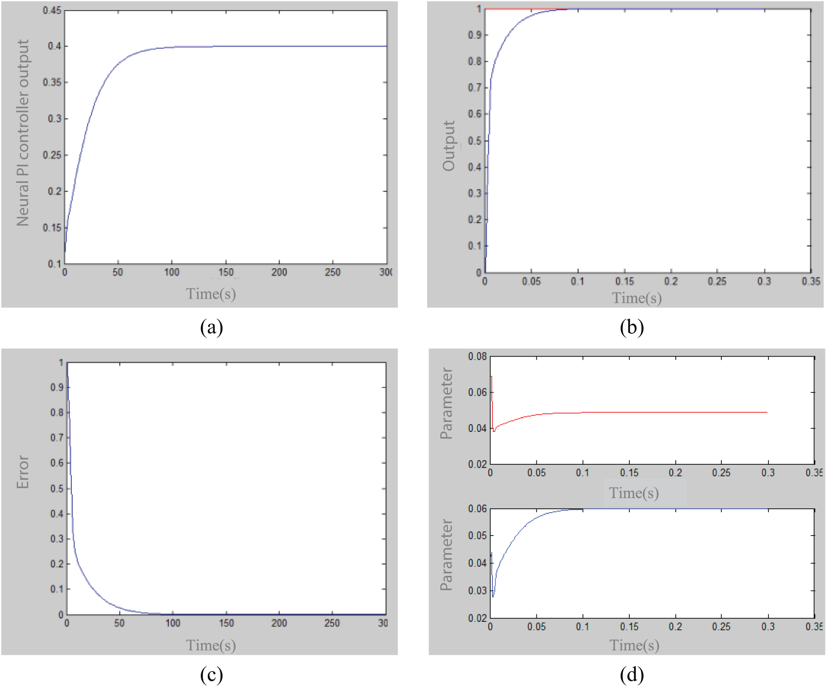
Response curve: (a) output y(k) of system, (b) output of neural network PI controller, (c) output of u(k) error and (d) output of
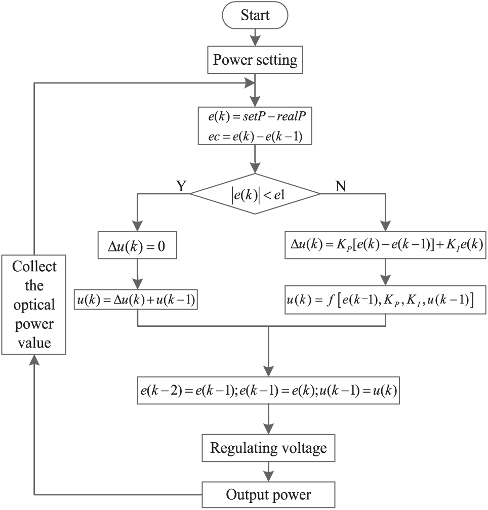
Flow diagram of BP neural network PI algorithm.
Experiments
According to the above principles and circuits, we have designed and manufactured a stable power control circuit of the laser, as shown in Figure 14(a). The output laser power with a wavelength of 940 nm is tested in the laboratory. The constant power modules of the laser are connected with the laser power detection probes, as shown in Figure 14(b). The output optical power of the laser is measured continuously using the computer output interface of the optical power meter and the drive current is sampled and transmitted by a current sampling circuit.
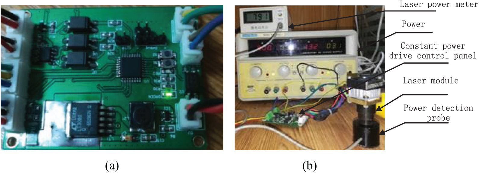
Control board of constant power drive and the experiment system of power measurement: (a) PCB board of constant power drive and (b) power measurement experiment.
Power stability test
In the laboratory, a power meter was used to measure the power of the designed constant power driven laser (with a power stable point of 493 mW), and the output value of the laser was continuously recorded, as shown in Figure 15. It can be seen that the long-term stability of the output power (20–30 h) fluctuated within ±6 mW when the closed loop was closed, and the power was on the rise. The short-term (30–40 min) power stability fluctuates within ±3 mW, and it can be seen that the circuit can achieve short-term and long-term stable output of the power drive of 2%.
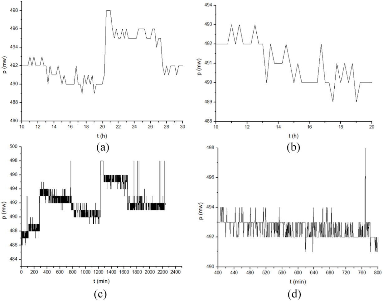
Power stability test curve: (a) permanent power stability, (b) short-term power stability, (c) 0–2400 min power curve and (d) 400–800 min power curve.
Current stabilization experiment
In order to check the stability of the current situation under the condition of stable power, the current acquisition circuit of the power point for collection and recording was used in the laboratory. As shown in Figure 16, in the closed-loop state (12 h), the long-term stability of the current fluctuates within ±2 mA, and the short-term stability can remain within ±1.5 mA. Perhaps due to temperature changes in the drive circuit, the current has a slight upward trend.
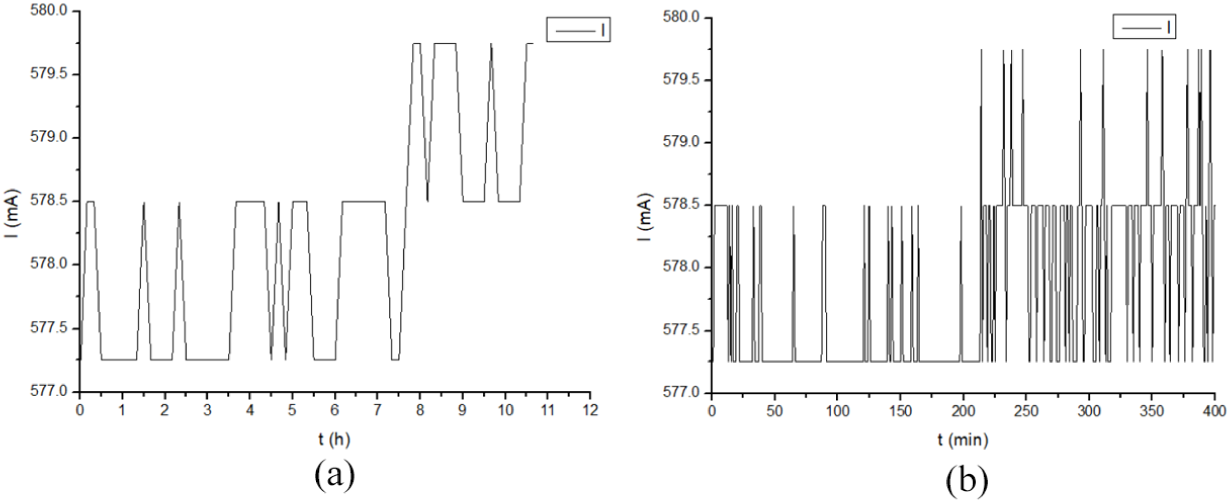
Current stability test curve: (a) current stability and (b) current curve.
It can be seen that the optical power output of the laser can reach 1000 mw and its long-term stability (48 h continuous) is within 2%. This meets the requirements of high-precision detection for the stability of the laser.
Conclusion
The laser has been widely used in industry, agriculture, medicine, precision measurement, holographic technology and other aspects, especially in the field of medical detection. The state explicitly requires blood stations and laboratories to use instruments to evaluate the results of enzyme-linked immunosorbent assay (ELISA). Enzyme standard colorimetric determination is the most basic function, the most basic requirement is that in a certain range of absorbance has better accuracy and precision, and can automatically accurately control the temperature of the instrument, this article through the research of the working characteristics of lasers designed a stable temperature characteristics of high-precision laser drive systems, mainly for medical enzyme standard instrument in colorimetric determination accuracy, precision and temperature requirements, to experiment to provide accurate, reliable and objective results. Aiming at the stringent requirements of the detection using semiconductor lasers for laser output power stability, a medium power semiconductor laser stable power control system based on the three closed loops is proposed on the basis of the analysis of the laser’s P–I/U–I characteristics and temperature characteristics, and a constant power control drive device for the semiconductor laser is designed. A model of the power control system based on neural PI is established and its core control algorithm is analyzed. Experiments show that the system can guarantee the requirements of the detection using semiconductor lasers for power long-term power stability. The control system is simple, flexible, low cost performance, and it can meet the technical index requirements of the detection using semiconductor lasers for long-term power stability.
Footnotes
Acknowledgements
The authors thank the editors and the anonymous reviewers for their valuable comments that helped to improve the paper.
Declaration of conflicting interests
The author(s) declared no potential conflicts of interest with respect to the research, authorship and/or publication of this article.
Funding
The work was supported the Shaanxi Province Postdoctoral Science Fund (no. 2017BSHEDZZ40), National Science Foundation of Shaanxi Province (no. 2018JM6023) and Science and Technology Project of Shaanxi Provincial Transportation Department (nos 17-16K, 17-33T).