
Abstract
Fuzzy control, an intelligent control method, is generally employed to deal with complex nonlinear controlled objects that cannot be expressed by accurate mathematical model. Memristor, whose unique advantages are automatic successive memory and nonvolatility, brought new opportunity for solving the key question of fuzzy control. With the design idea of software harden, this paper first constructed membership function in the fuzzy controller based on the unique feature of crossbar array of the spintronic memristor and elaborated the whole construction process. After that, this paper simulated the construction process with MATLAB simulation software, verifying its reasonability and feasibility. Furthermore, a typical fuzzy control water tank system was chosen to explore and discuss the flexibility of spintronic memristor crossbar array in the real-time control system, and the proposed control strategy and the typical fuzzy control strategy were compared. The results revealed that the proposed control strategy was able to attain the effectiveness of the typical fuzzy control system in the real-time control system. This sets light to future research on the implementation of memristor crossbar array in the real-time control system and also promotes the application of fuzzy controller design idea. The problems needed to be solved when implementing memristor crossbar array in the real-time control system were discussed in the final section.
Keywords
Introduction
In May 2008, the HP researchers announced that they had developed the physical device of the memristor, and they also demonstrated its physical structure and verified its existence, 1 which was described in the published paper of professor Chua in 1971. 2 Henceforth, this caused the wide attention in both academia and industry. A memristor is a passive two-terminal nonlinear component, 3 and it has huge potential in nonvolatile memory,4,5 large-scale integrated circuit, 6 biological bionics, 7 artificial neural networks, 8 pattern recognition,9,10 picture processing,11–13 and chaotic circuits. 14 Because of its unique switch mechanism, natural memory function, continuous input and output characteristics, and nanoscale size, the memristive effect of HP memristor was achieved in a solid-state thin film two-terminal device by moving the doping front along the device. However, reading and writing on the memristance have to be achieved by applying a pulse signal in the practical application of HP resistor. The pulse signal makes the deviation of predefined memristance arise, and the deviation affects the accuracy of the whole circuit. In 2009, Chen proposed a spintronic memristor model according to magnetic technology, and its memristive effect can be realized by the spin-torque-induced magnetization switching or the magnetic-domain-wall motion. 15 Compared with HP memristor, the relationship between the memristance and the current of spintronic memristor can be controlled more flexibly. Meanwhile, its technology to integrate magnetic device on the top of CMOS device is more mature. In the process of magnetic memory’s development, spintronic devices are widely used in the areas of modern intelligent control, signal processing, and pattern recognition because of its unique properties.
Fuzzy control is a kind of rules-based intelligent control method, which is established on fuzzy mathematics theory. Zadeh puts forward the concept of “fuzzy sets” for the first time in 1965, 16 after that fuzzy control was born, where we can describe some values of variables linguistically, such as too high, very fast, slightly lower, and substantial. It is different from classical control theory and modern control theory in the aspect that the fuzzy control theory is not dependent on the accurate mathematical models of the controlled plants. Fuzzy control provides a new way to control the complicated nonlinear plants. 17 In addition to the above advantages, fuzzy control has many other merits such as easiness to be accepted by people, simple structure, robustness, good adaptability, continuous output, and high reliability. Hence, a great number of fuzzy control systems have been developed and integrated into modern domestic applications, for example, washer, camera, copying machine, refrigerator, and air condition.
At present, hardware implementation of fuzzy control is almost based on digital realization method, that is, it is realized by digital hardware devices (such as FPGA and DSP). However, the operation precision of digital hardware devices is limited, so the abilities for keeping the balance between the adaptability and performance of the system are very finite. Another disadvantage is that digital hardware devices are very poor in acting as an evolvable hardware. Furthermore, the fuzzy algorithm realized by precise digital technology is obviously against the nature of fuzzy concepts. 18 This paper proposed a method that its operation is performed in analog, that is, through a simple hardware based on spintronic memristor crossbar structure for implementing fuzzy membership function. Its theoretical calculation accuracy is unlimited because it is an analog circuit system.6,14 Furthermore, another virtue is that its evolvability can be achieved by changing the memristance of crosspoints. The contribution of this paper is twofold. First, with design idea of software harden, this paper constructs fuzzy controller membership function based on spintronic memristor crossbar array and articulates the establishment process with MATLAB simulation technique. Second, this paper verifies the feasibility and validity of memristor-based fuzzy controller when implementing in the real-time control system.
The paper is organized as follows. In the “Model of spintronic memristor” section, we describe the mathematical model of the spintronic memristor and then build the corresponding Simulink model. “The design of fuzzy membership function by spintronic memristor crossbar array” section is devoted to the elaboration of the principle of implementing fuzzy membership function based on spintronic memristor crossbar structure. “The computer simulation results and analysis” section presents a design scheme based on spintronic memristor crossbar structure for implementing fuzzy membership function and proves the validity of the proposed scheme through simulation for Simulink model. In the “Discussion and conclusion” section, the validity of the proposed scheme is verified through a classic example of fuzzy control—the control system of hot and cold water valve—and also a brief conclusion is presented.
Model of spintronic memristor
Mathematical model of spintronic memristor
There are many physical structures of spintronic memristor nowadays. The model discussed in this paper is based on the theory of magnetic-domain-wall motion, as shown in Figure 1. Spintronic memristor is composed of a long spin-valve strip which includes two ferromagnetic layers: reference layer and free layer. The magnetization direction of reference layer is fixed by being coupled to a pinned magnetic layer. The free layer is divided by a domain wall into two segments that have opposite magnetization directions to each other. The resistance per unit length of each part is determined by the relative magnetic directions of the free layer and reference layer. If the magnetization direction of the free layer is parallel to that of the reference layer, the resistance per unit length of the part is low; otherwise, the resistance is high.
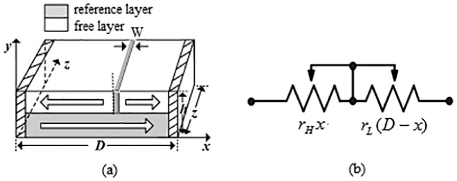
(a) The structure and (b) the equivalent circuit of spintronic memristor.
In Figure 1(a), D, z, and h are the length, width, and height of the spintronic memristive device, respectively, and the values are 1000, 10, and 7 nm, respectively. W is the width of the domain wall which moves under the effect of applied voltage, and if the length of two segments at opposite directions to each other changes, the resistors of the device change accordingly. The rL and rH denote the resistance of unit length when the segment of spin-valve strip is at the low- or high-resistance state, respectively. If the width of the domain wall is ignored, the resistance of spintronic memristor can be expressed as

where x is the moving distance of domain wall. Domain wall movement velocity v is proportional to the current density J. Its relationship can be written as
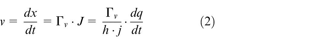
where
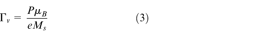
where P is the magnetizability of materials,
Equation (2) is integrated and substituted into equation (1), and the resistance of spintronic memristor can be calculated as

Here,
Considering the domain wall width of the spintronic memristor and the influence of the resistance, equation (1) can be expressed as
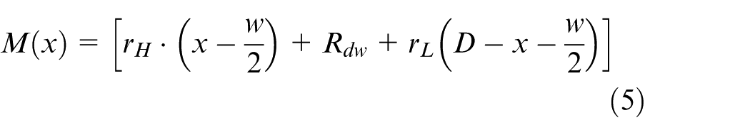
where Rdw and w are the memristance and the width, respectively. We assume that the position of the domain wall is at the middle of it and the resistance of the thin film strip changes linearly from rL to rH; thus, the memristance of the device can be rewritten as
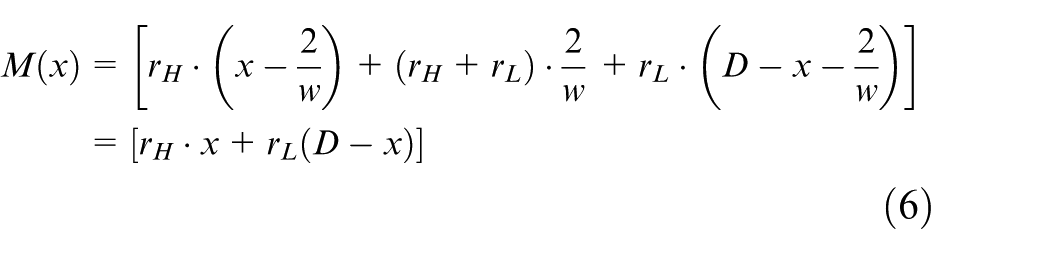
Equations (6) and (1) are identical, so we can conclude that when 0 < x < D, the memristance is not associated with the domain wall width. The relational expression of the distance x and the rate v of domain wall movement is
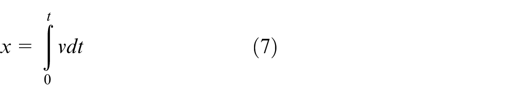
Equations (2) and (3) show that the relationship between the rate v of domain wall movement and current density can be expressed as
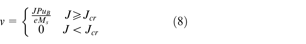
Substituting equation (8) into equation (7)
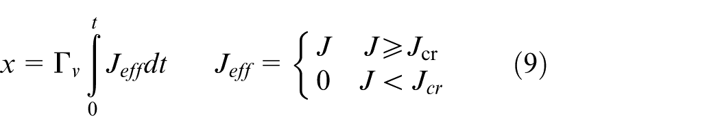
where Jeff is the effective current density of the device, and Jcr is defined as the critical current density and its size is associated with its characteristics. The theoretical calculation formula is
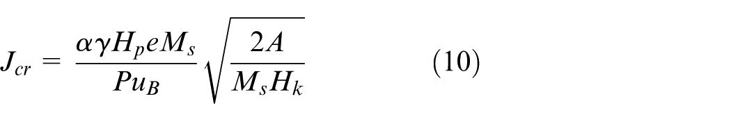
Here, α and γ are the damping parameter and gyromagnetic ratio, respectively. Hp is the hard anisotropy, Hk is the easy anisotropy, and A is the exchange parameter. The memristance is changed while the current density J is greater than the critical current density Jcr. The current density of the device is
Here, V is the voltage applied to the spintronic memristor and M(x) represents memristance.
As well known, the theoretical calculation results of equation (10) cannot explain all the experimental measurements, so Jcr is seen as the inherent electrical parameters obtained by experiment directly.
The Simulink model of spintronic memristor
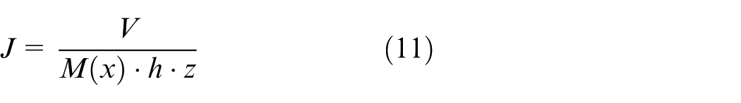
The Simulink model of spintronic memristor is established based on the theoretical basis, as shown in Figure 2. The model is made up of input signal v(t), the parameter module (rL, rH, Jcr, D, h, z), the internal operation module (summator, multiplier, and integrator), condition judgment module (If), and merge module. The parameter settings are as follows: rH = 6 kΩ, rL = 4 kΩ, x0 = 0.3 × 10⁻⁶ m, Γ v = 1.3517 × 10⁻¹¹, Jcr =5 × 10⁷ A/cm2, D = 1000 nm, h = 7 nm, z = 10 nm. The input voltage is V0 sin(2πft), and its amplitude and frequency are 1.05 V and 10 MHz, respectively.
Simulink model of the spintronic memristor.
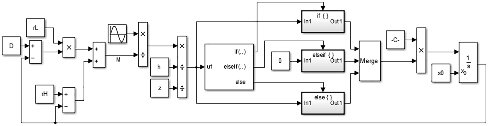
Figure 3 shows the simulation results of the spintronic memristor. The input voltage is shown in Figure 3(a). The I–V curve appears in a typical gradient hysteresis loop shape (as shown in Figure 3(b)), which demonstrates that the spintronic memristor is a kind of nonlinear component. At the same time, the switching characteristic is shown in Figure 3(b). Figure 3(c) shows the relationship between the memristance and the applied voltage. The memristance of spintronic memristor remains between minimum and maximum (i.e. between 4 and 6 kΩ) along with the changing voltage. Variation of it along with time is shown in Figure 3(d). The memristance of spintronic memristor remains between maximum and minimum with time while the amplitude of the voltage remains 1.05 V (red curve). The memristance will never reach resistance boundary when the amplitude is 0.37 V. The memristance changes if, and only if, the current density is larger than the critical current density (blue curve).
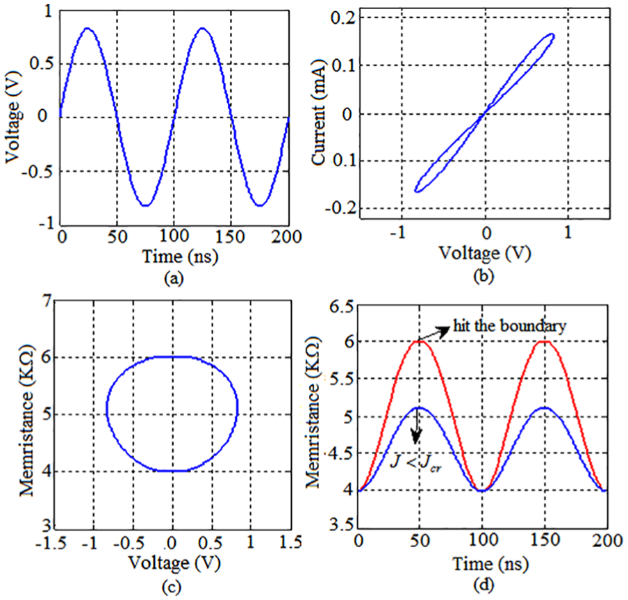
Characteristic simulation curves of the spintronic memristor: (a) Time-Voltage curve (b) Voltage-Current curve (c) Voltage-Memristance curve (d) Time-Memristance curve
Crossbar array of spintronic memristor
Crossbar array is composed of two groups of conductive parallel wires perpendicularly intersecting with each other. The region where a wire in one set crosses over a wire in another set is called crosspoint. 19 Crosspoints are usually separated by a thin film material whose properties can be changed. For example, its resistance can be changed by controlling the voltage applied to it. This paper adopts the structure of spintronic memristor crossbar array.
Figure 4 shows a typical structure of crossbar array of spintronic memristor. The memristors are fixed between the crosspoints of crossbar array, with its two terminals, respectively, connected with the corresponding transverse and longitudinal wires. Memristance of every memristor can be simply changed by applying suitable voltages to those wires between which memristor is fabricated.
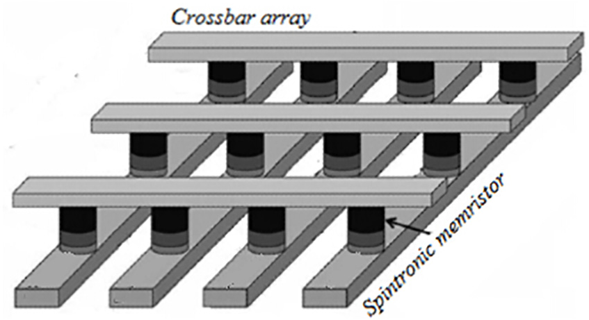
Crossbar array of the spintronic memristor.
The system of spintronic memristor crossbar array stores the analog information in the corresponding crosspoints through different memristance. So the crossbar array of memristor is a kind of ideal circuit structure of a two-dimensional fuzzy relation. The vertical and horizontal wires in the crossbar array can represent different discrete values of input and output variables. And the two-dimensional matrix of memristor on the crosspoint can be expressed by fuzzy logic relationship.
The design of fuzzy membership function by spintronic memristor crossbar array
This section presents a design scheme of fuzzy membership function of spintronic memristor crossbar array based on the above principles, which is the implementation of fuzzy membership function with spintronic memristor crossbar array.
The implementation principle of fuzzy membership function by spintronic memristor crossbar array
The fuzzy membership function with any shape can be implemented by crossbar array of memristor. 18 Figure 5 shows the hardware implementation of Gaussian membership function (fuzzy set A) and the generalized bell membership function based on the spintronic memristor crossbar array. This paper then articulates the theory of simulating membership function of fuzzy sets based on spintronic memristor crossbar array.
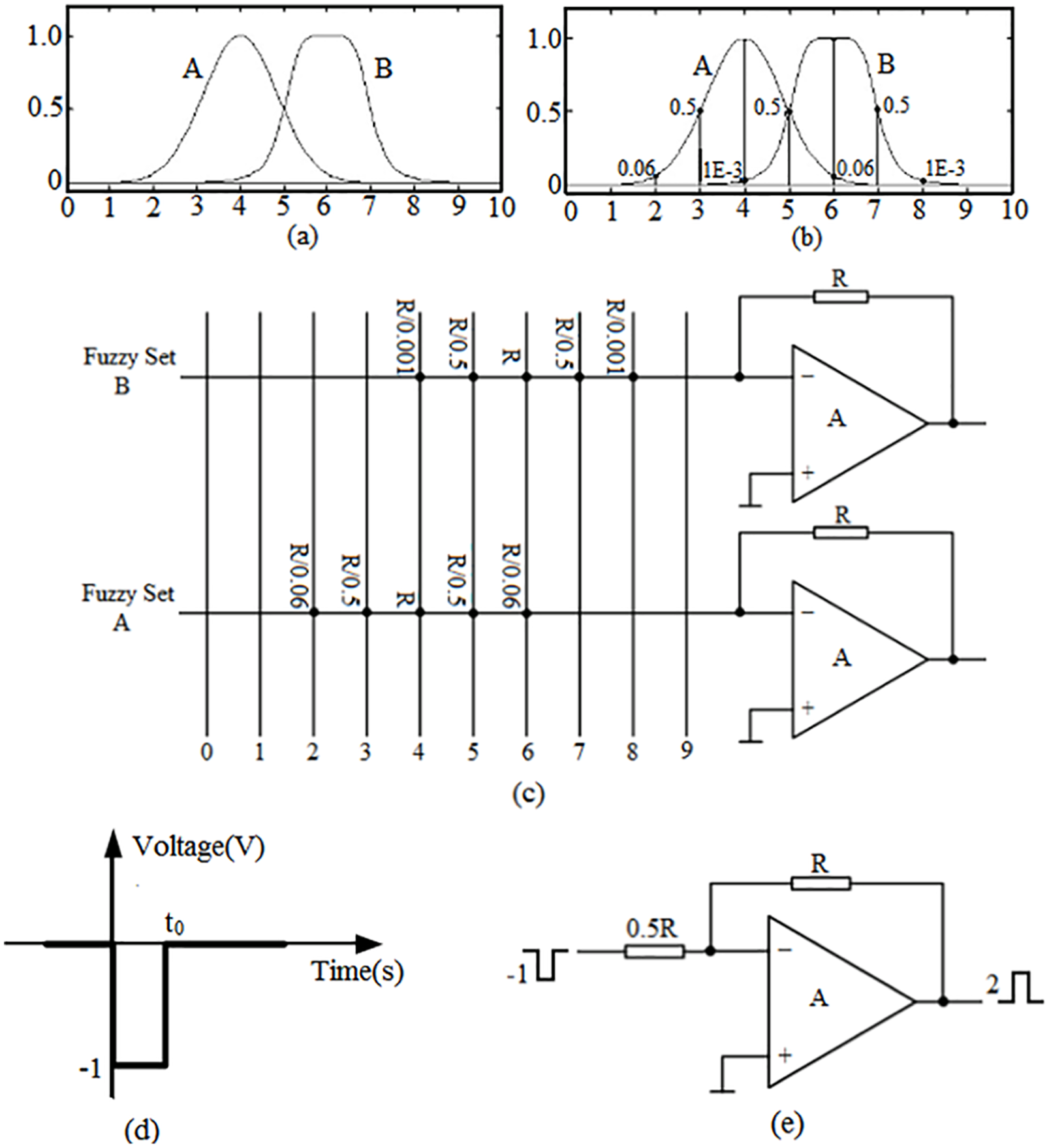
Hardware implementation of Gaussian membership function and the generalized bell membership function based on the crossbar array of spintronic memristor: (a) continuous form of Gaussian membership function and the generalized bell membership function, (b) discrete form of Gaussian membership function and the generalized bell membership function, (c) the hardware implementation of Gaussian membership function and the generalized bell membership function based on the spintronic memristor crossbar array, (d) a negative narrow pulse with amplitude −1 which should be applied to that column of the crossbar which represents input sample, and (e) equivalent circuit when the input sample is x = 5.
We assume that µ(·) is the domain and represents the system function of fuzzy sets. We build the system of spintronic memristor crossbar array. The xi is input sample of the system, and µ(xi) is output sample of the system.
First of all, we assume that A and B are two fuzzy sets. A(·) and B(·) are defined as the membership functions of A and B, respectively. The x is the input signal, as shown in Figure 5(a). In almost all applications, the input signals are sampled and quantified with finite resolution. Without loss of generality, the input signals are quantified with quantizer so that its quantitative spacing is equal to 1. The input variable is only a discrete integer value, so fuzzy sets A and B and their membership functions A(·) and B(·) are also the discrete values, as shown in Figure 5(b). Hardware implementation schematic diagram of fuzzy membership function based on spintronic memristor crossbar array is shown in Figure 5(c). In this case, there are two rows in the crossbar, which represent the fuzzy sets A and B, respectively. A(·) is implemented in lower row and B(·) is implemented in higher row of the crossbar. Each column represents the value of input variable x in the crossbar. Memristance of memristors on the crosspoints should be set to the corresponding values near the crosspoints. Take the membership function A(·) as an example. Memristance of memristors M(xi) on the crosspoint xi of the horizontal wire and vertical wire on the low row can be expressed as
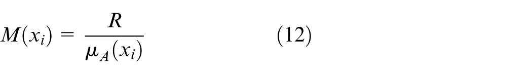
where µA(xi) represents the membership function of fuzzy set A at crosspoint xi, and R denotes the feedback resistance of operational amplifier. The memristance on the other crosspoints whose values equal to 0 should be set to the maximum memristance Roff.
The circuit as shown in Figure 5(c) works with the following principle. We assume that the input signal sample xi equals 5, and the narrow pulse whose amplitude −1 is applied to the sixth column from the left (which corresponds to x = 5), and other columns are grounded. Pulse voltage will not change memristance if the current density J calculated according to equation (11) is not above the critical current density JCR. The equivalent circuit is shown in Figure 5(e) with the pulse signal (as shown in Figure 5(d)) applied to the spintronic memristor (as shown in Figure 5(c)). The output values of fuzzy sets A and B are both 2 which are equal to membership functions, µA(xi = 5) and µB(xi = 5). The input signal is the quantitative sample of input variable x.
The output signals are the membership functions of A and B, that is, µA(x) and µB(x). When the input sample x = 9, the output value of operation amplifier is equal to R/Roff, and the ideal output value should be 0. Therefore, the resistance R should be selected as small as possible. In addition, samples of the input variable are considered to be a singleton instead of fuzzy number, because of applying negative narrow pulse to one column while grounding other terminals.
Through the above two examples, we can verify the following conclusions that the fuzzy set membership function with any shape and any number can be implemented by the hardware circuit of crossbar array based on the spintronic memristor. Moreover, if the number of crossbar array is increased, that is to reduce the input signal sampling interval (e.g. reduce from 1 to 0.5 in the above two examples), the resolution of the input signal can be increased.
Fuzzification
In a fuzzy system, the number of the controller output is divided into single variable fuzzy control and multivariable fuzzy control. In the single variable fuzzy controller, the number of input is defined as the dimension of fuzzy control and divided into one-dimensional fuzzy controller, two-dimensional fuzzy controller, and three-dimensional fuzzy controller. Theoretically, the higher the dimension of fuzzy controller is, the higher the rate system control progress is. Fuzzy control is too complicated with too high dimension, and computer implementation of control algorithm based on the fuzzy synthesis reasoning is more difficult. So, we first consider the simplest case in the fuzzy control, that is, one-dimensional controller of a single variable fuzzy control. The input signal is the error e, and the output signal is y; e and y, normalized to [0, 1], are denoted by corresponding fuzzy set, which is divided into negative big (NB), negative small (NS), zero (ZO), positive small (PS), and positive big (PB).
Fuzzy sets can be denoted by membership functions. Membership function is the essence of fuzzy set and the basis of fuzzy computing. It translates the word computing into numerical calculation, and puts the brain’s thinking process into computer program calculation. There are many common membership functions such as bell-shaped membership function, triangular membership function, and trapezoidal membership function. The paper selects the triangular membership functions as the membership functions of input and output signals, as shown in Figure 6.
Simulink model of the fuzzy membership function based on crossbar array of the spintronic memristor.
Knowledge base
Knowledge base includes the control objective of the knowledge and demands in the specific application field. It consists of database and rule base of fuzzy control.
Database
Database is used to store the membership degree vector value of all fuzzy subsets of input and output variables. It provides data to the inference engine in the process of solving fuzzy relation equation of rules inference.
Rule base
Rule base of fuzzy controller is based on expert knowledge or experience accumulated in a long term by operating personnel. It is a kind of language representation according to intuitive reasoning. Fuzzy rule is usually connected by a series of relational words. The most relational words commonly used are “if-then” and “also.” The “and” is used in the multivariable fuzzy control system. In “if … then,” the part “if …” is called “the premise part,” and “then …” is called “the conclusion part.” The basic structure of fuzzy rule is “If A and B then C.”
Rule base is used to store all the fuzzy control rules. It provides control rules to the inference engine when reasoning.
Fuzzy reasoning
Fuzzy reasoning is the core of fuzzy controller, and it has the inferential capability like men’s based on the fuzzy concept. In the fuzzy controller, fuzzy reasoning is accomplished by fuzzy control rules so as to solve the fuzzy relation equation and obtain function part of fuzzy control volume. In the specific controls, inference method of simple operations is usually adopted considering the reasoning time. The basic method is Zadeh’s approximate reasoning, which includes forward reasoning and backward inference. Fuzzy control usually adopts forward reasoning, so does the design in this paper.
Defuzzification
Acquisition of the reasoning results denotes that the function rules inference of fuzzy control has been done. But the result is still a fuzzy vector, not a control volume. It must undergo a transformation and obtain clear control output, which is defined as defuzzification.
Defuzzification consists of the following two processes. First, the quantity of fuzzy control becomes the clear amount that represents theoretical domain range through defuzzification transformed. Then the clear amount is turned into the actual quantity of control according to the change of scale.
The methods of defuzzification usually include the method of middle of maximum (mom), smallest of maximum (som), last of maximum (lom), the median method (bisector), and weighted mean method (centroid), among which weighted mean method is used extensively.
Weighted mean method takes the average value z0 of
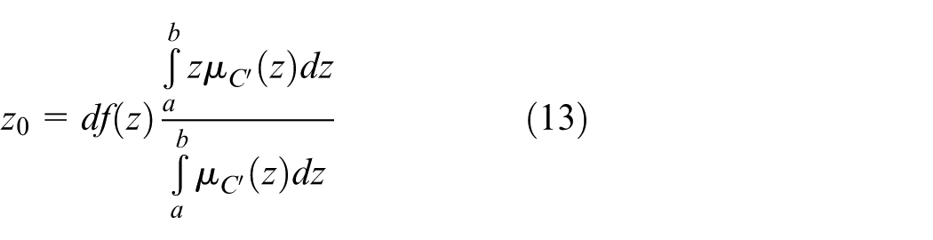
It is similar to the calculation of gravity center; hence, it is named as centroid. In the case of discrete theory domain, the computational formula of the clear amount is
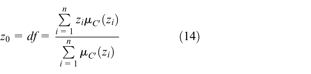
After obtaining z0, the clear amount is turned into the actual quantity of control. The defuzzification method in this design adopts method of weighted mean, and the computational formula is equation (14).
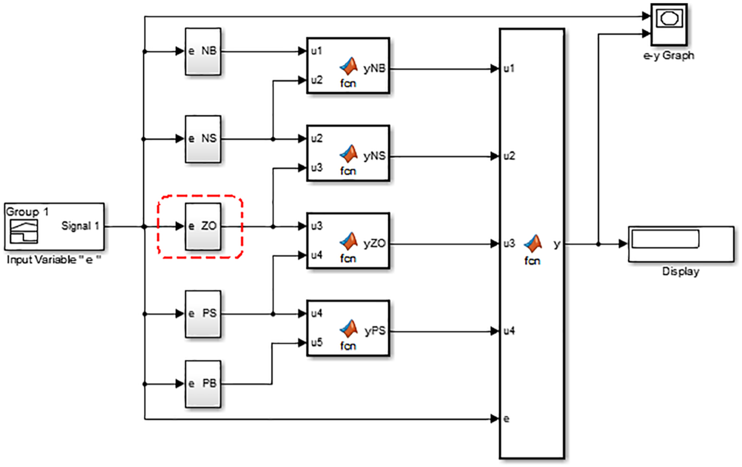
The Simulink model of fuzzy membership function based on crossbar array of the spintronic memristor is shown in Figure 6. The subsystems NB, NS, ZO, PS, and PB implement five membership functions NB, NS, ZO, PS, and PB. Take ZO for an example (the red dotted line frame is shown in Figure 6); the Simulink model of its subsystem is shown in Figure 7. In the model, the left sides of two columns (the blue dotted line frame) are the different memristance of the spintronic memristor crossbar array.
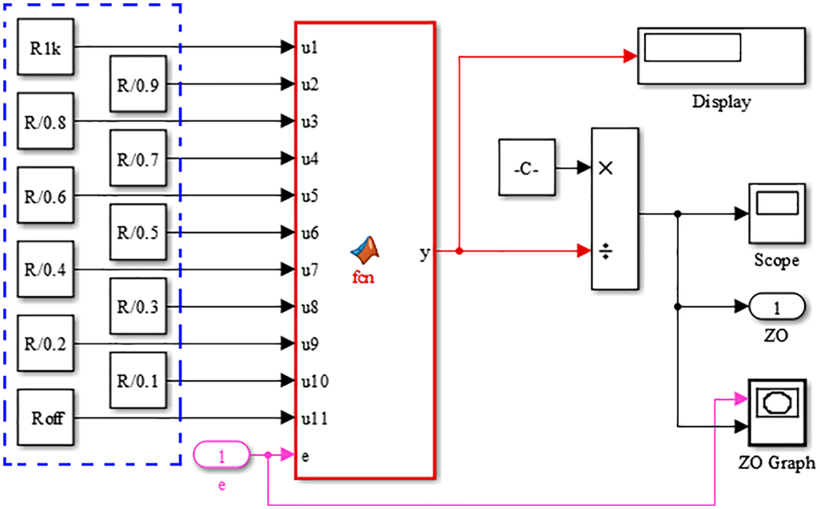
Simulink model of subsystem of ZO membership function.
We obtain the following result through the Simulink simulation of the above design scheme. The waveform of membership function of crossbar array based on spintronic memristor and fuzzy module are shown in Figure 8, respectively. The membership function of input e of fuzzy module is shown in Figure 8(a), and the membership function of input e of crossbar array based on spintronic memristor is shown in Figure 8(b). We can conclude that the membership function implemented by crossbar array of spintronic memristor reaches basically the demand through comparing the two waveforms. It is worthy to mention that the triangular membership function curve is not smooth because of two reasons: the adopted sampling number is finite, so there is a certain error. Waveform will be smoother through increasing the sampling points. Waveform which appears in the shape of ladder relates to simulation step size. The shape of ladder is obvious, because the simulation step size is small, but the precision is high. Waveform will become smoother if the step size is increased.
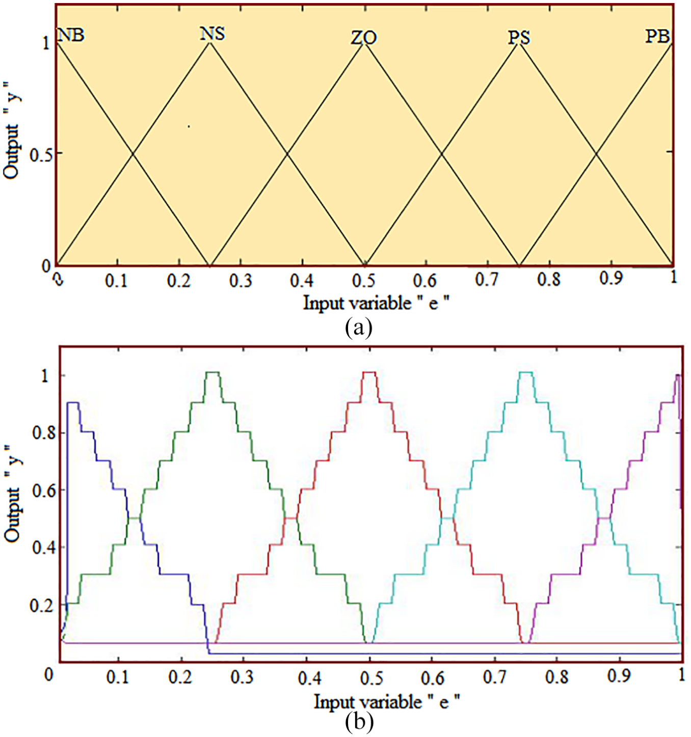
The simulation waveform of crossbar array based on spintronic memristor: (a) the input membership function of the fuzzy set and (b) the membership function based on crossbar array of the spintronic memristor.
Furthermore, take error e = 0.6, for instance; the output calculated by fuzzy module is y = 0.978 (as shown in Figure 9(a)), and the output calculated by the membership function based on the crossbar array of spintronic memristor is y = 0.9778 (as shown in Figure 9(b)). If taking to the results of three decimal places, y = 0.978 which equals to the value of fuzzy module.
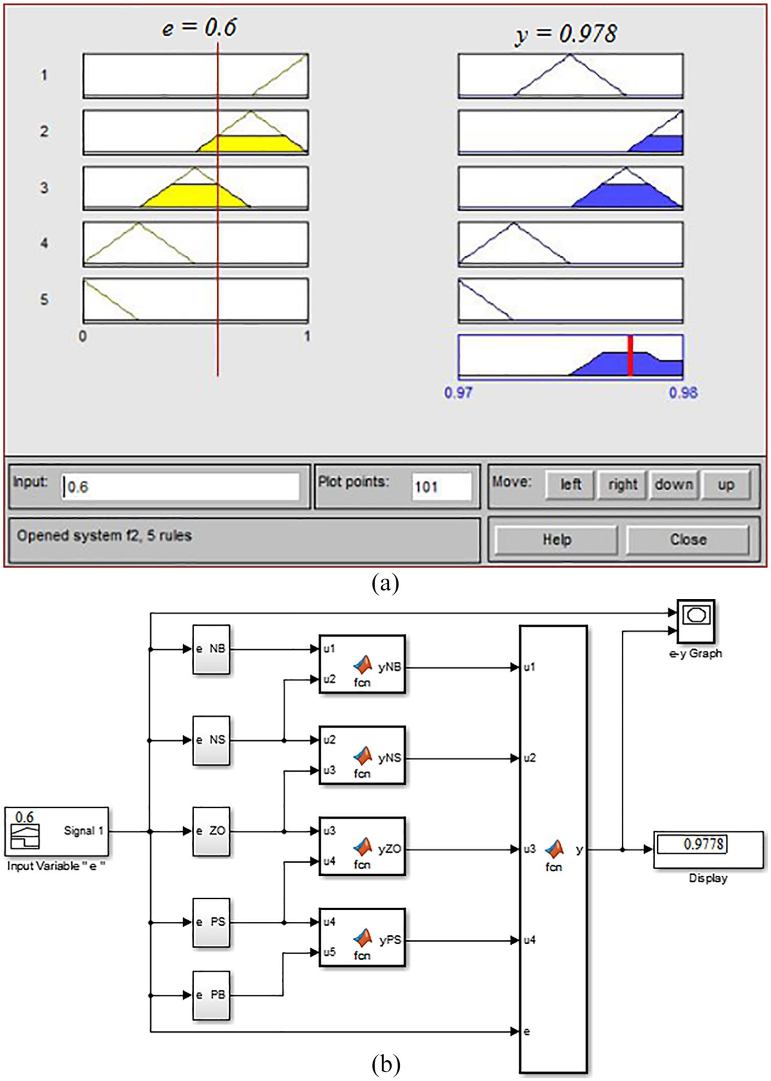
Comparison of membership function between fuzzy module and the crossbar array of spintronic memristor: (a) the results of y of fuzzy module when e = 0.6 and (b) the results of y implemented by the membership function based on the crossbar array of spintronic memristor.
The computer simulation results and analysis
The implementation scheme of the fuzzy control membership function based on spintronic memristor crossbar array which is structured in this section is applied to classic case of fuzzy control system of hot and cold water valve.
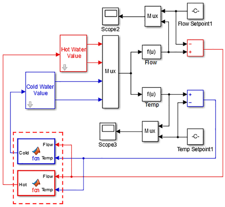
Figure 10 is the Simulink model of the control system of hot and cold water valve. In this system, hot and cold water valve is controlled by fuzzy control algorithm: two input signals of fuzzy controller are flow error and temperature error signals, respectively, and two output signals are cold and hot water valve control signals, respectively.
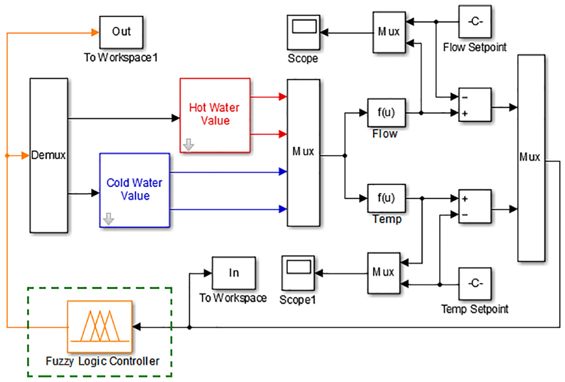
Simulink model of the control of cold and hot water valve.
The fuzzy control membership function is shown in Figure 11. Figure 11(a) shows the signal of membership function of flow error, and Figure 11(b) shows the signal of membership function of temperature error. Figure 11(c) and (d) shows the signals of membership function of control system for cold and hot water valve. Fuzzy control rules are shown in Table 1.
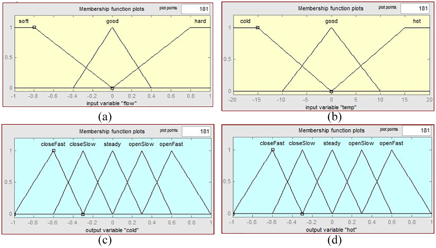
Fuzzy control membership function of cold and hot water valve of shower: (a) membership function of flow error, (b) membership function of temperature error, (c) membership function of the control system for cold water valve, and (d) membership function of control system for hot water valve.
Fuzzy rules of the control system of cold and hot water valve.
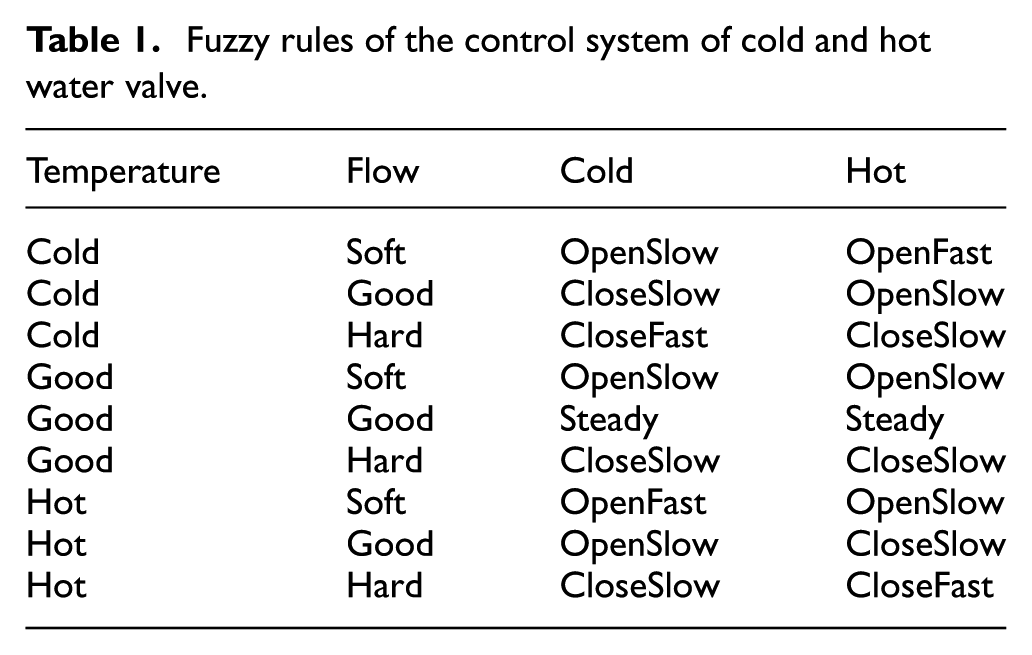
Figure 12 is the Simulink model of the cold and hot water valve control system, which is based on spintronic memristor crossbar array. The two subsystems, which are shown in dashed box of the figure, are cold water and hot water valve control signals. The input signals of the two subsystems are the temperature and flow error signals. The output signal of the cold subsystem is the cold water valve control signal. The output signal of the hot subsystem is the hot water valve control signal.
Simulink model of the control system of cold and hot water valve, based on crossbar array of spintronic memristor.
Figure 13 is the Simulink model of the cold subsystem. The hot subsystem is constructed same as cold subsystem. The corresponding membership function of the flow and temperature input signals is deposited in the dotted line box as shown in the subsystem. The defuzzification method of the design adopts the method of weighted mean.
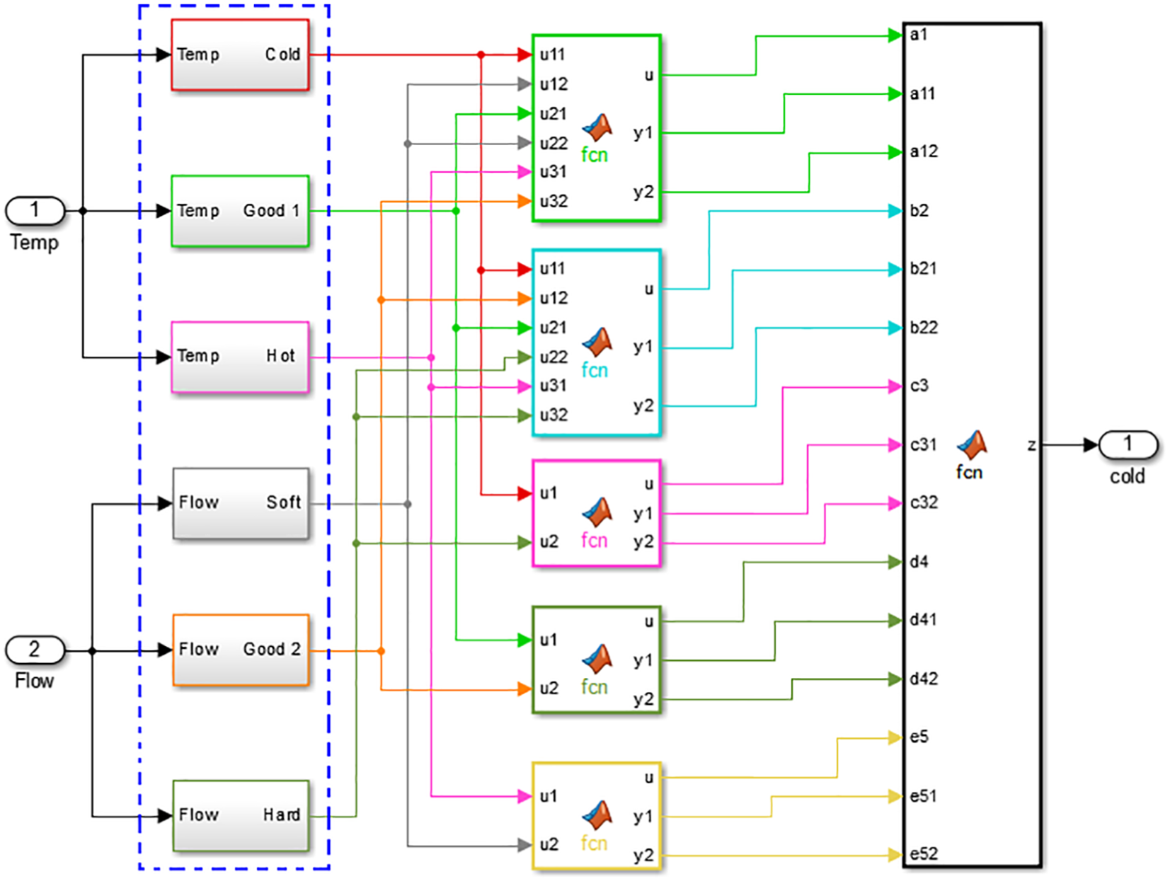
Simulink model of the cold water valve control subsystem.
The simulation results for the system of traditional fuzzy control algorithm and the system consisting of the fuzzy control membership function based on crossbar array of spintronic memristor are shown in Figure 13.
Figure 14(a) and (c) shows the flow and temperature waveform figure, which results from conventional fuzzy control algorithm. Figure 14(b) and (d) shows the flow and temperature waveform figure, which results from the fuzzy control membership function based on crossbar array of spintronic memristor algorithm. Blue curve shown both in Figure 14(a) and (b) is the flow reference value for the two systems, while the pink curve represents the actual flow of the two systems. In Figure 14(c) and (d), the pink curve represents the reference temperature of the two systems, and blue curve indicates the actual temperature of the two systems. After the comparison of the flow and temperature waveform figures between these two systems, we can conclude that system of the fuzzy control membership function based on crossbar array of spintronic memristor can achieve the basic requirement of controlling the temperature and flow rate.
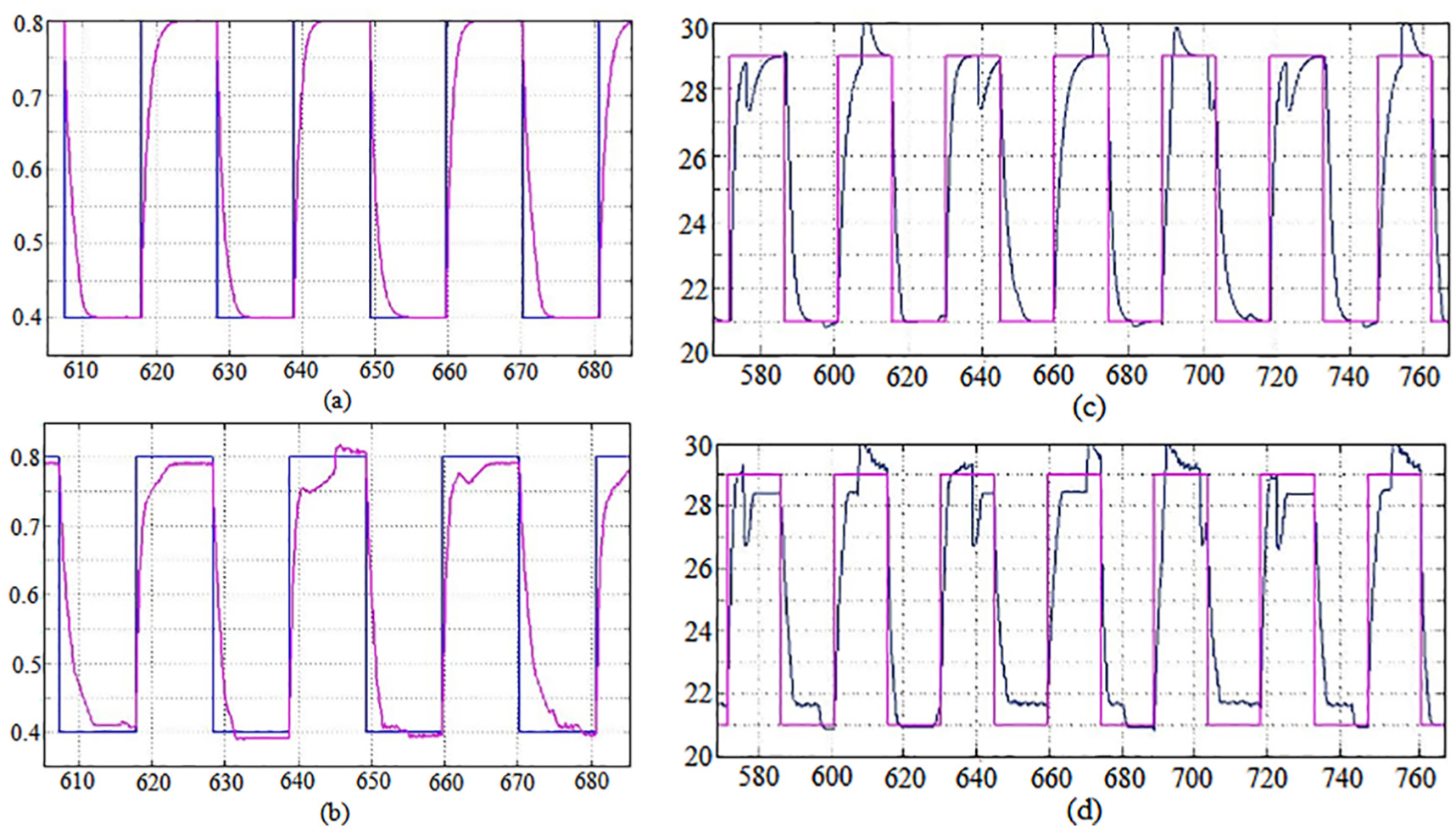
Simulation results of flow for different fuzzy control system: (a) classical fuzzy control system, (b) the fuzzy control membership function based on crossbar array of spintronic memristor control system, (c) temperature waveform of classical fuzzy control system, and (d) temperature waveform of the fuzzy control membership function based on crossbar array of spintronic memristor control system.
Figure 15 is the error curve for reference value and the actual output. Figure 15(a) and (c) shows the simulation results of flow and temperature error curve of conventional fuzzy control algorithm. Figure 15(b) and (d) shows the simulation results of flow and temperature error curve of system of the fuzzy control membership function based on crossbar array of spintronic memristor. After the comparison between Figure 15(a) and (c), (b) and (d), we can conclude that the error curve for the system of fuzzy control membership function based on crossbar array of spintronic memristor in flow and temperature is similar with the original system. The peak value is slightly less than the original system. Through calculation, the original system in flow and the temperature of the mean square error are 0.0070 and 2.4430, respectively. Meanwhile, systems of the fuzzy control membership function based on crossbar array of spintronic memristor in flow and the temperature of the mean square error are 0.0068 and 2.3968, respectively. It is slightly better than the original system and meets the requirements of the original system of error.
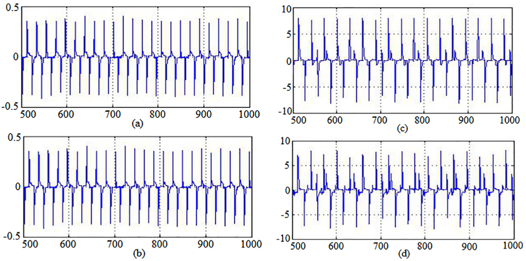
The error curve between the reference and the output value curve: (a) the flow error curve of the classical fuzzy control system, (b) the flow error curve of membership function based on crossbar array of the spintronic memristor, (c) the temperature error curve of the classical fuzzy control system, and (d) the temperature error curve of membership function based on crossbar array of the spintronic memristor.
The fuzzy control membership function system based on crossbar array of spintronic memristor can replace traditional fuzzy controller to realize the accurate control of temperature and flow rate.
Discussion and conclusion
In this paper, we first analyzed the physical structure, the operating principle, and the accurate mathematical model of the spintronic memristor systematically. And then we established the Simulink model of the spintronic memristor and verified its correctness through the numerical analysis on it. On this basis, we demonstrated the theory of the crossbar array of spintronic memristor and the fuzzy set membership function. Combining these together, we presented the design scheme of fuzzy control membership function based on crossbar array of spintronic memristor and analyzed its feasibility theoretically. Through the analysis of simulation result of this Simulink model and the comparison with relevant curves in the fuzzy modules, we verified the correctness of this design scheme. Furthermore, we applied the hardware implementation scheme of the fuzzy control membership function based on spintronic memristor crossbar array to the classic case of fuzzy control system of hot and cold water valve and proved the effectiveness of the construction through system simulation, thereby laying the foundation for hardware realization of fuzzy control algorithm. Finally, it is suggested that we could combine this circuit configuration with Proportion, Integral and Differential control to realize the adaptive fuzzy PID control for further research. However, the proposed system also has three problems needed to be solved in the future. The first one relates to the uncertainty of reading and writing patterns of memristor. Different reading and writing patterns result in different levels of energy consumption; 20 thus, a comparative analysis is required. The second problem is how to construct the peripheral circuit of memristor crossbar array so that it can accurately detect and give the trigger signal of the memristor. Third, the low-frequency working circuit and the high-frequency memristor can trigger the separation of circuit; thus, how to effectively avoid the coupling effect between them is another future research direction.
Footnotes
Declaration of conflicting interests
The author(s) declared no potential conflicts of interest with respect to the research, authorship, and/or publication of this article.
Funding
The work was supported by Intelligent Agricultural Equipment Project, National Key Technologies R&D Program in the 13th Five-Year Plan Period (Grant 2017YFD0701101-3); Chongqing Technology Innovation and Application Demonstration Project (Industry Key R&D, Grant cstc2018jszx-cyzd0182); Social Cause and Livelihood Security S&T Innovation Project, Chongqing Science & Technology Commission Key Technologies R&D Program (Grant cstc2017shms-zdyfx0006); and Chongqing Key Innovation Program of Common Fundamental Technologies in Main Industries (Grant cstc2015zdcy-ztzx8002).