
Abstract
In order to improve the vibration responses of rotor system, this paper presents an active vibration control technique for a rotor-bearing-actuator system with the use of robust eigenvalue placement method. By analyzing the characteristics of the piezoelectric stack actuator, bearing and rotor, a rotor-bearing-actuator system is modeled. Based on this dynamical model, a reduced-order technique is used to establish the state equation in the modal space. A robust eigenvalue placement method, which can enhance the robustness of system to model error and uncertain factors by optimizing the close-loop eigenmatrix with a small condition number, is proposed to carry out the active vibration control for system. The good results indicate that the eigenvalue can be placed to precise position, and the displacement responses get effectively suppressed with the proposed method. Meanwhile, the optimized close-loop eigenmatrix can possess a small condition number, which means the system has achieved excellent robustness.
Introduction
Rotary machine components are used in the areas of mechanical engineering such as the machine tools, textile, paper and printing industries. The rotor vibrations caused by unbalances, process forces and system instabilities affect the machining accuracy and machine reliability, so an increasing amount of research is focused on the effective vibration control method for rotary machine.1–5 Considering the advantages such as wide application and high stability, the active control is more suitable for adjusting to a myriad of load conditions and machinery configurations compared with the passive control. 6
The dynamical model of rotor system is essential for active vibration control design. The accuracy of the dynamical model influences the control design and response analysis, and many researchers have investigated the dynamical behaviors of rotor system.7–13 Sharan et al. 7 calculated the dynamical responses of the rotor system to random excitation based on a finite element method along with the model analysis method. Considering the nonlinear characteristics of bearing, Shin 8 and Chen et al. 9 regarded the rotor-bearing as an integral system and explained the phenomenon of the “bearing softening” effect with the change of speed. Furthermore, Li and Shin14,15 took the thermal expansion factor into account to analyze dynamical responses of the rotor-bearing system. In the field of piezoelectricity, Zine et al.11,12 proposed a suitable piezoelectric accelerometer mathematical model to select appropriate accelerometer frequency range that minimizes measurement error and improves accuracy. A model of the physical behavior of piezoelectric sensor was extracted. 11 Nondimensional model and parametric studies were given by Xinlei and Wei-Hsin. 13
The active vibration control strategy is the core technique which determines the control quality of system. With the rapid development of the control theory, more and more control methods were applied to active vibration control (Takaba, 2015).16–21 Abdul-Jabbar et al. 16 designed a state feedback controller with optimal control theory to achieve desirable transient responses and a feed-forward controller to counteract the effect of the external excitations for a flexible rotor running with flexibly mounted journal bearings. The optimal control was applied to rotor-bearing-support systems, in which the rotor finite element models have relatively large degrees of freedom (DOF). 17 The active piezoelectric actuator bearings and self-learning control method had been used for active vibration control of a rotor system with varying initial state errors by Li et al., 10 and the experimental results confirmed the success of control strategy. Based on the proportional–integral–derivative (PID) control method, Lau et al. 18 used the giant magnetostrictive material–based actuators in active control of journal bearing system to analyze the shaft orbit and achieved the desired responses. Palazzolo et al. proposed three methods, which are the optimal control, eigenvalue placement and simplified method for the vibration control of a rotary machine using piezoelectric stack actuator. By integrating actuator saturation, Xu et al. designed an effective acceleration feedback H∞ active vibration control for seismic excited building structures. Eigenvalue placement method is widely used in nonlinear network system (Takaba, 2015), while for rotor system, Palazzolo et al. 20 deemed that the eigenvalue placement method is careless about the robustness of system.
However, an active vibration control technique for a rotor-bearing-actuator system by using robust eigenvalue placement method is presented in this paper. To improve the accuracy of the dynamic model of system, the outer ring of bearing and the piezoelectric stack actuator are modeled, and the rotor-bearing-actuator system is more consistent with the actual condition. Then the state equation of reduced order in the modal space is established for control design. In order to achieve good robustness of the system to model error and uncertain factors when applying eigenvalue placement method for active vibration control design, a robust method is proposed. The good results indicate that this method is capable of placing the eigenvalue to precise position and achieving excellent robustness of system at the same time.
Dynamical model of system
The piezoelectric stack actuator consists of a stack of piezoelectric ceramic disks which are arranged on the top of one another and are connected in parallel electrically. Due to the excellent mechanical-electromagnetic properties, it is widely used in active vibration control field and is researched by many scholars.10,20–23 The sketch of a piezoelectric stack actuator is shown in Figure 1.
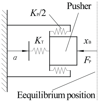
Sketch of the piezoelectric stack actuator.
The prescribed displacement α is proportional to the input voltage, and the pushing force Fp will induce a displacement xB. The relationship of force balance can be expressed as
where Kα is the synthetical stiffness, and KT and KP are the stiffness of stack of piezoelectric disks and preload spring, respectively.
With the advantages such as high positioning accuracy and excellent mechanical properties, angular-contact ball bearing is widely used in all kinds of rotating machinery. Based on the raceway control theory and the Hertz contact theory, the running condition of the bearing can be obtained by solving the balance equations of ball and inner ring. 24 The relationship between load and displacement of the inner ring can be expressed in the form of matrix as 25

where
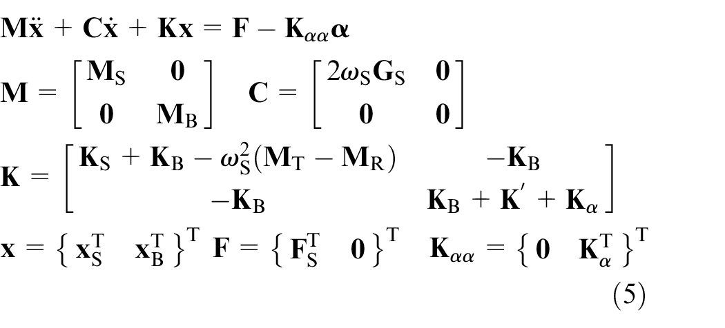
The dynamical model of system is a set of mathematical relationships, which relates intrinsic dynamic parameters (mass, damping, stiffness, etc.) to external loads (control force and cutting force). In this work, a mathematical model of the rotor-bearing-actuator system is needed to carry out the design for active vibration control. Inevitably, some basic assumptions and simplifications in this model should be made as follows:
The rotor is a continuous elastic and rotating symmetric shaft.
The machinery parts rotating with the rotor (inner rings of bearings and nuts) are simplified into the sleeves.
The bearings and supporting parts are modeled as a set of springs.
The outer ring of front bearing, which cannot be ignored, is equivalent to a mass.
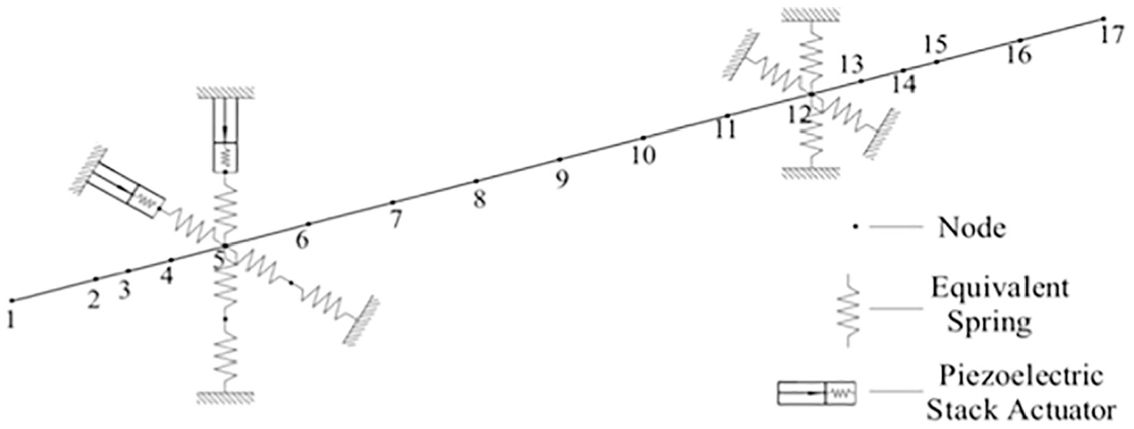
Then the modeled rotor-bearing-actuator system is depicted in Figure 2. The piezoelectric stack actuators push the outer ring of front bearing, which is a circular ring with a mass and is considered as two equivalent linear springs in the opposite directions. The bearings are equivalent to springs to support the horizontal flexible steel shaft.
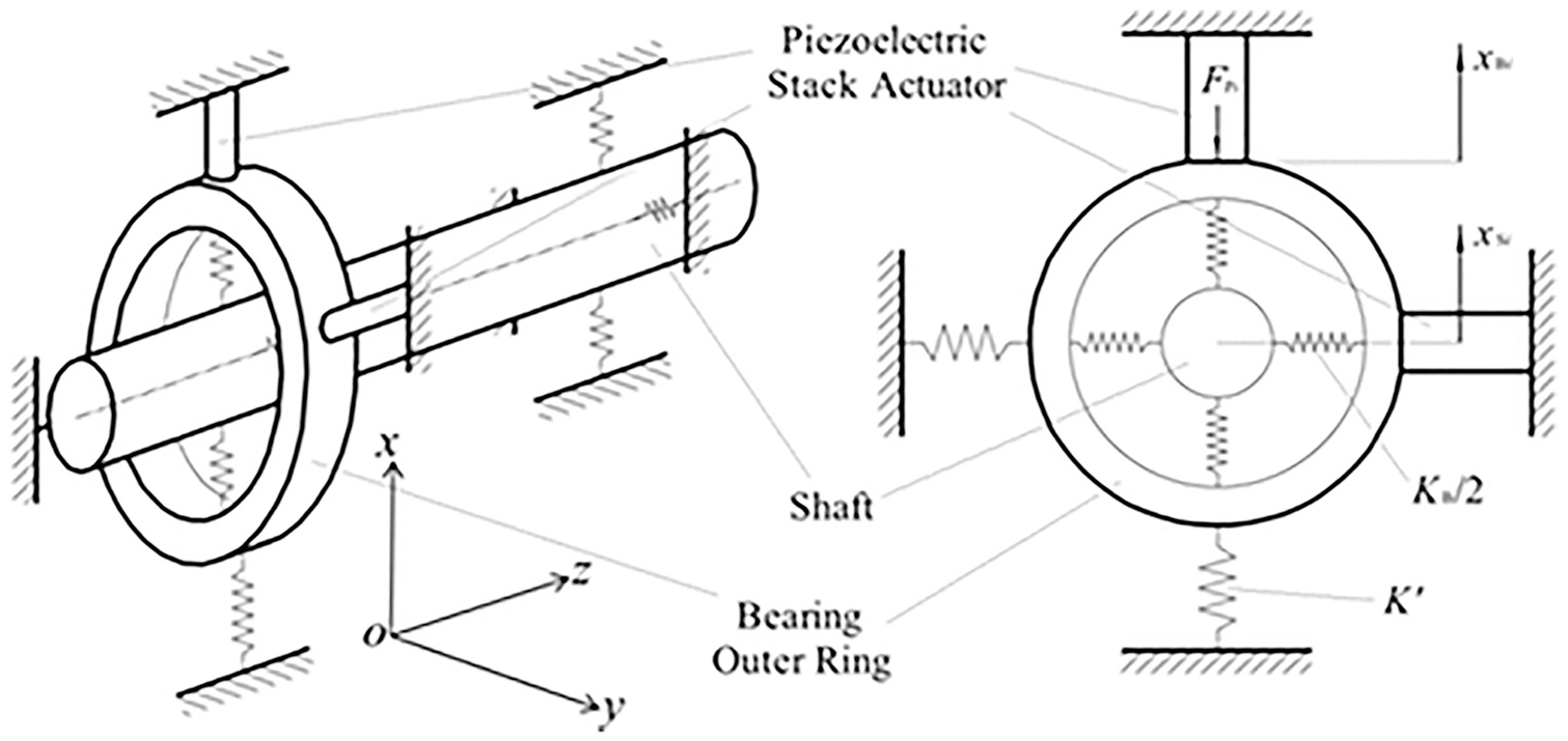
Model representation.
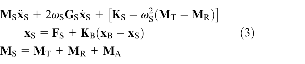
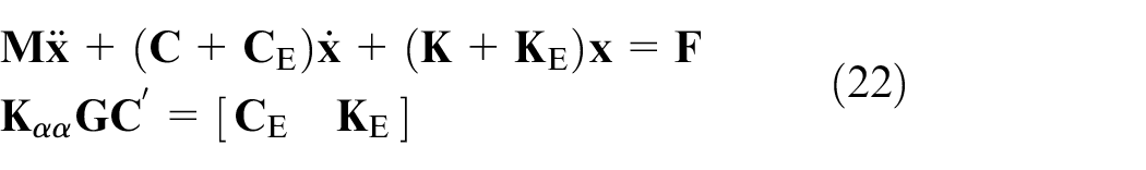
By neglecting damping effect and both axial forces and displacements, 26 the dynamical model of the rotor including the simplified sleeves can be written as follows
where
The dynamical model of the outer ring of front bearing can be written as follows

where
By using mathematical means, the rotor-bearing-actuator model is expressed as
where
Control design
To obtain a suitable analytical model, a reduced-order technique substituting previous low-order models for the overall performance is used to reduce the dimensionality of system. Applying this method, the reduction is achieved by changing from the physical coordinates

where
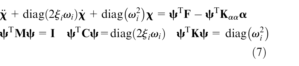
where ξi and ωi are the damping and stiffness of the ith modal, respectively. The equation of state in the modal space can be written as a first-order form by adding an identity equation as follows 10
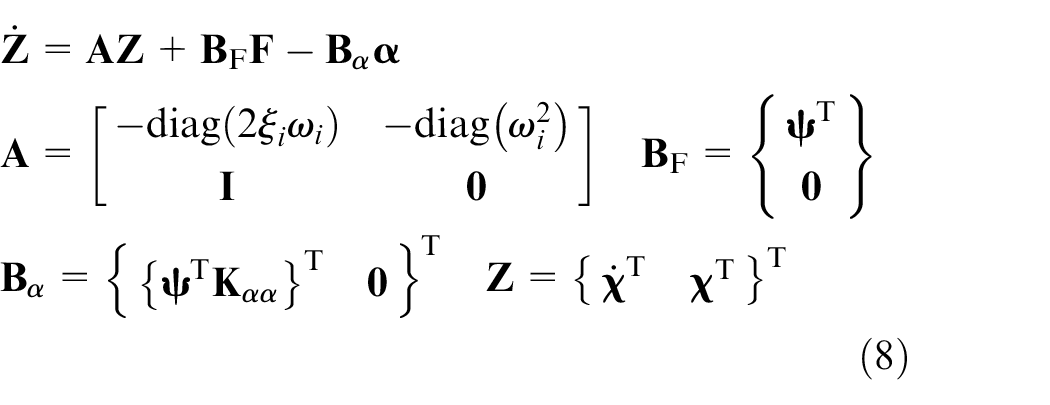
where
where
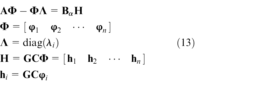
With the use of the output feedback method, the eigenvalue and eigenvector of system can be improved, and the system will present a desired response, while the feedback gain matrix which can accomplish the same aim of eigenvalue placement is not unique. 27 This important property indicates that the eigenvector placement has many choices, so we can make use of this property to enhance the robustness of system to model error and uncertain factors. Based on the theory of matrices, 27 the condition number of eigenmatrix, which is made up of eigenvectors, is a measure of robustness of the system. With the same eigenvalue placement, the smaller the condition number of eigenmatrix, the better the robustness of the system. Based on this, the control design of robust eigenvalue placement is conducted.
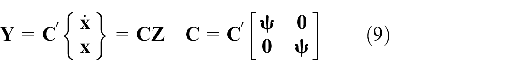
The feedback relationship between prescribed displacement vector and output vector is expressed as follows

where

The eigenvalue and eigenvector of the closed-loop system can be obtained by

where
where

If we regard the matrix (

where

where

So
According to equation (18), we can introduce the optimization problem of finding the desired closed-loop orthonormalized eigenvector

And the constraint condition

By obtaining the desired closed-loop eigenmatrix
Substituting equation (21) in equation (13), we obtain the final optimized closed-loop eigenmatrix
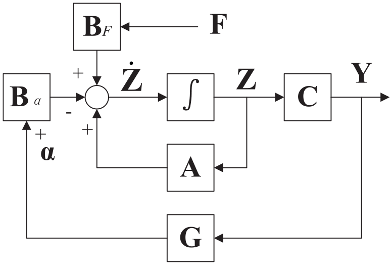
Block diagram for system control.
Substituting equation (10) into equation (5), we obtain the closed-loop dynamical equation
where
Applications
The proposed methodology is numerically applied to a system consisting of a horizontal flexible steel shaft, two angular contact ball bearings and two piezoelectric stack actuators. The finite element method and the Timoshenko beam theory are used for dynamical modeling of the system, 28 and the model is shown in Figure 4.
The finite element model of the rotor-bearing-actuator system.
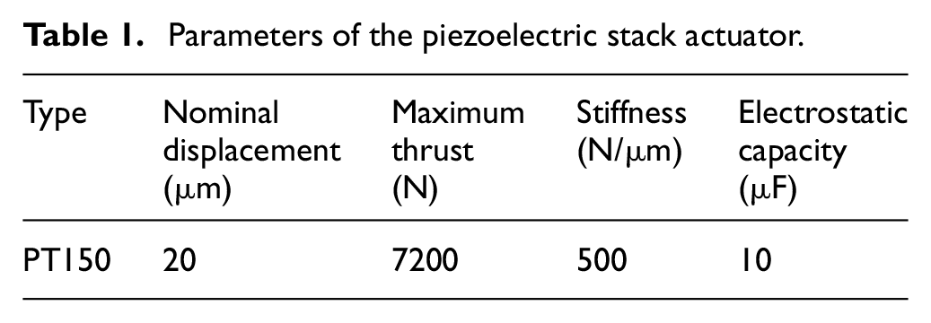
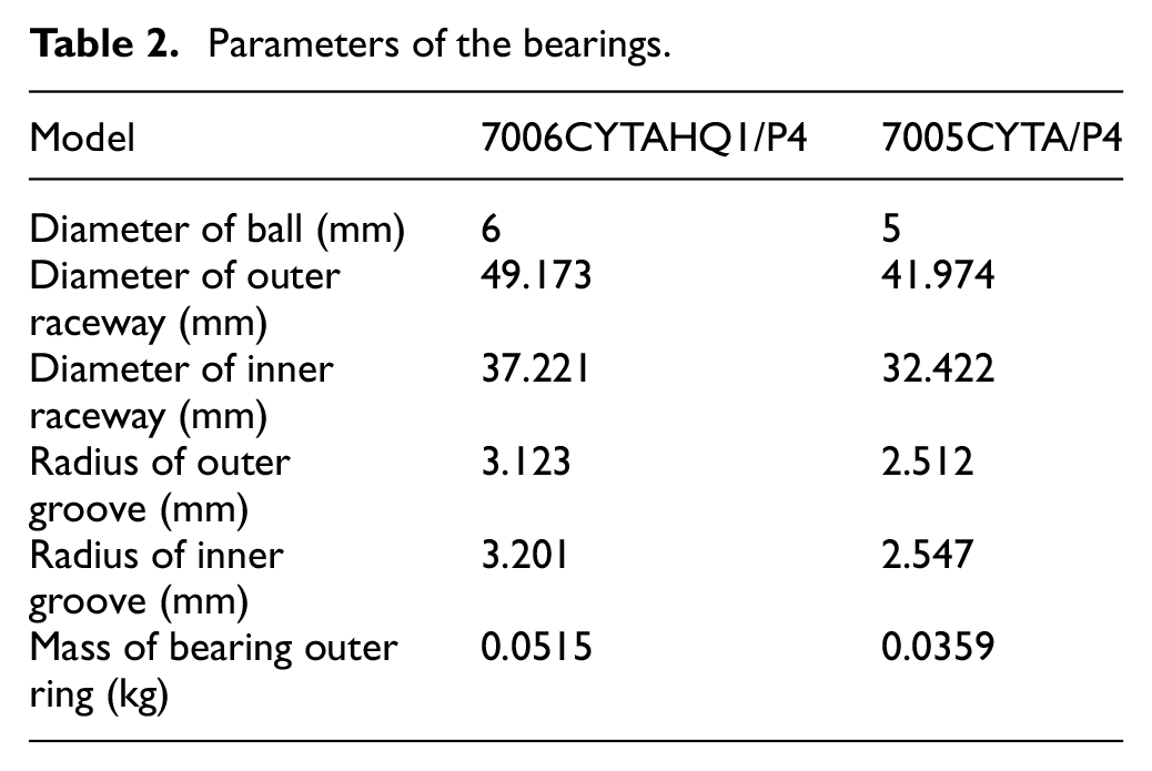
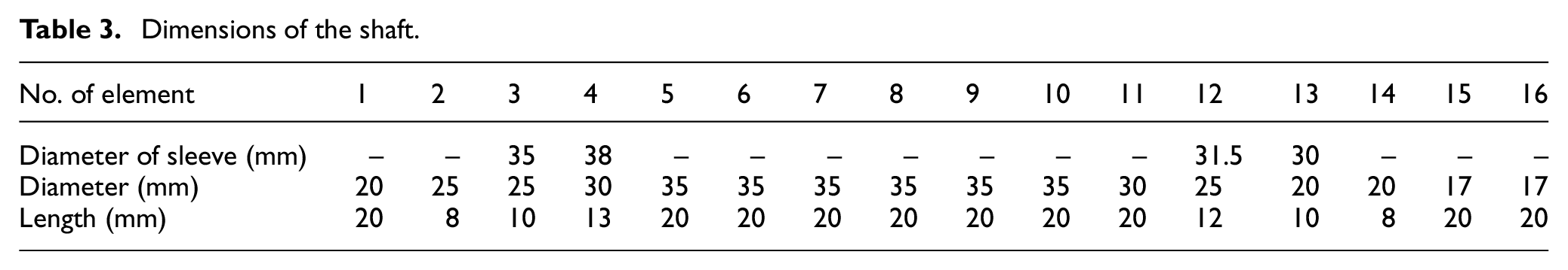
The physical and electrical parameters of the piezoelectric stack actuator are given in Table 1, the physical and geometric properties of bearings are given in Table 2 and the physical dimensions of shaft is given in Table 3.
Parameters of the piezoelectric stack actuator.
Parameters of the bearings.
Dimensions of the shaft.
The feedback signals come from the velocity and displacement of node No. 1 and No. 5, and all the equations in this paper are solved by commercial software MATLAB. The displacement responses at the shaft end and front bearing outer ring are presented as the typical cases. When solving the dynamical equations, the first eight order models are generated, and while carrying out the control design, the first two order models in every orthogonal direction are generated. Since the system has the same properties in the two orthogonal directions, only one of them will be analyzed.
With the speed rising from 1000 to 10,000 r/min, the stiffness of bearings will vary, which is shown Figure 5. The radial stiffness increases because the centrifugal force of ball increases the contact stiffness between the ball and outer ring. While the axial and angular stiffness decrease because the centrifugal force of ball decreases the contact stiffness between the ball and inner ring which is the main factor influencing the axial and angular stiffness.
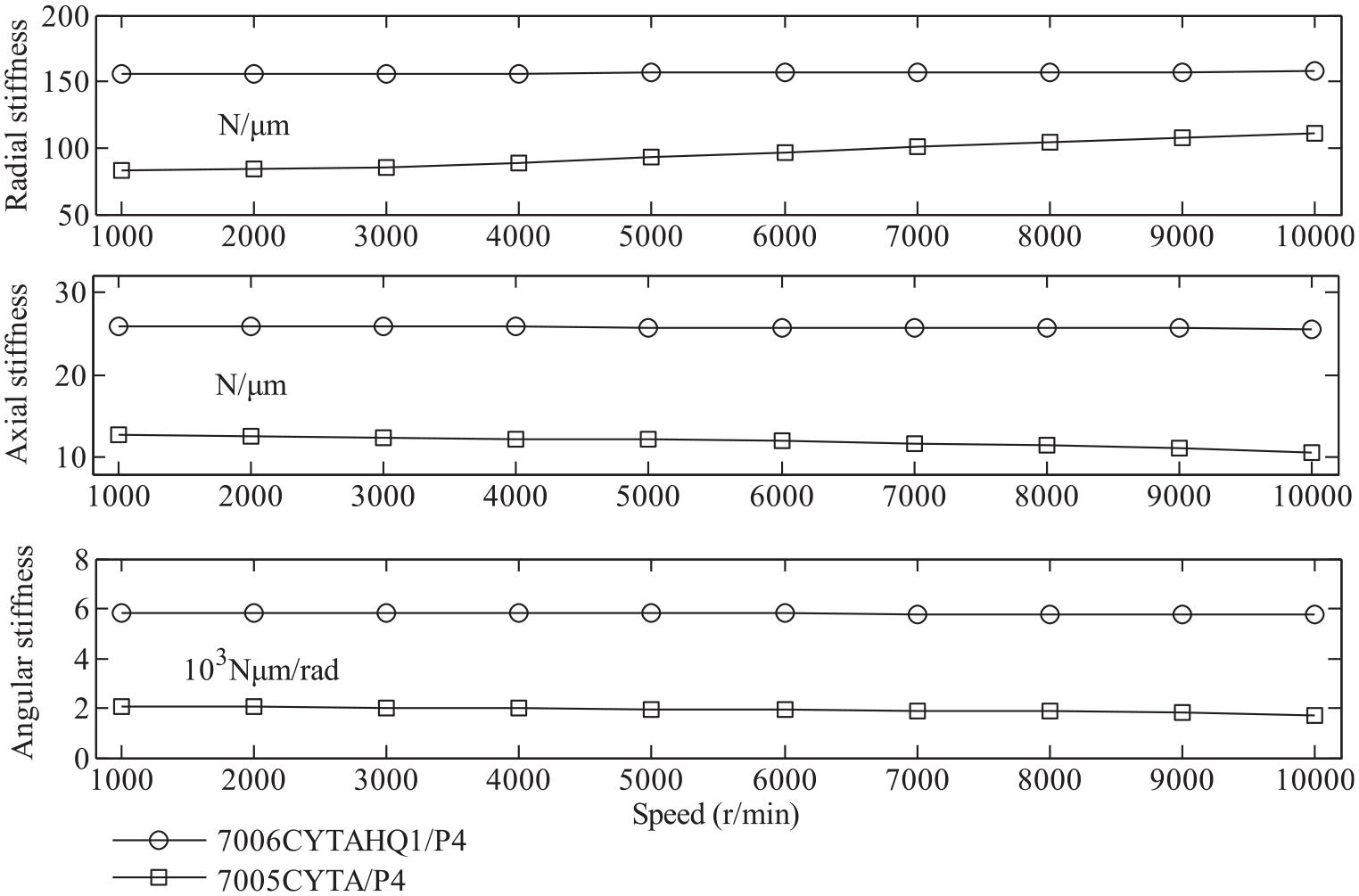
Bearing stiffness.
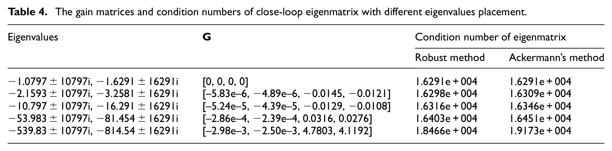
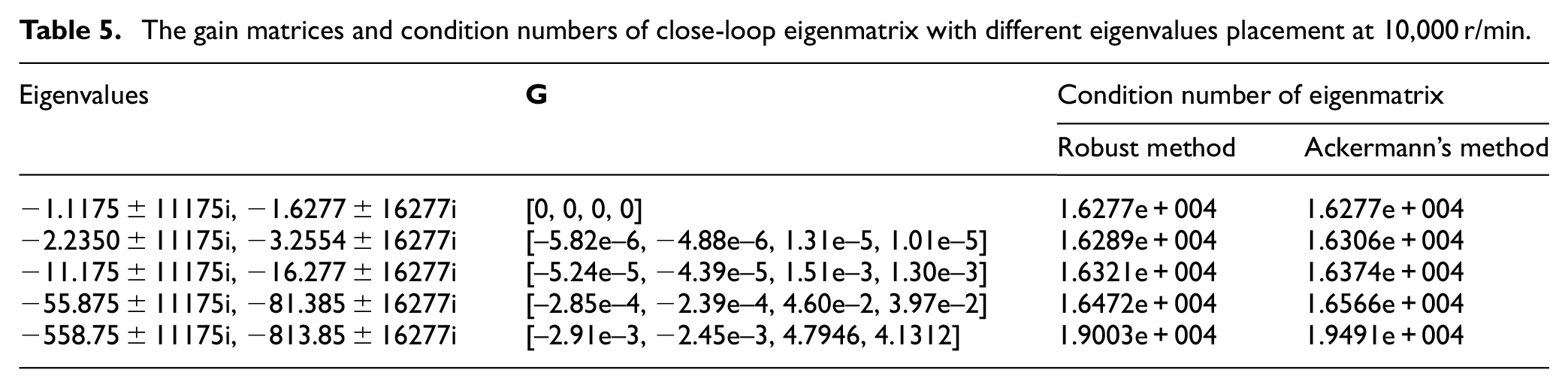
Based on the robust eigenvalue placement method mentioned earlier, the closed-loop eigenvalues have been placed at different locations, and the corresponding gain matrices have been achieved and are shown in Table 4. It will need lot of control energy if allocating the imaginary parts of the desired close-loop eigenvalues which are determined by the stiffness of system and hardly change, so they have no change compared with open-loop system in this study. While the real parts of the desired close-loop eigenvalues are determined by the damping of system and easily change, and they must be located in the left half of complex plane to ensure the system stability. 29 Therefore, the real parts of the desired close-loop eigenvalues to different locations are configured on the left half of complex plane. With the increase in the absolute value of real parts, the system becomes more and more stable. Accordingly, the absolute value of first two numbers and the value of last two numbers of gain matrices become larger, which indicates that the system needs more control energy.
The gain matrices and condition numbers of close-loop eigenmatrix with different eigenvalues placement.
The displacement responses at the shaft end and front bearing outer ring are shown in Figure 6 (5000 r/min) and Figure 7 (10,000 r/min). When a step-input load of 40 N is applied on the shaft end, the vibration displacements at the shaft end and front bearing outer ring show different responses with different eigenvalues and gain matrices. At 5000 r/min and without control, the equilibrium position of vibration at shaft end with eigenvalues being 1.0797 ± 10797i, −1.6291 ± 16291i and
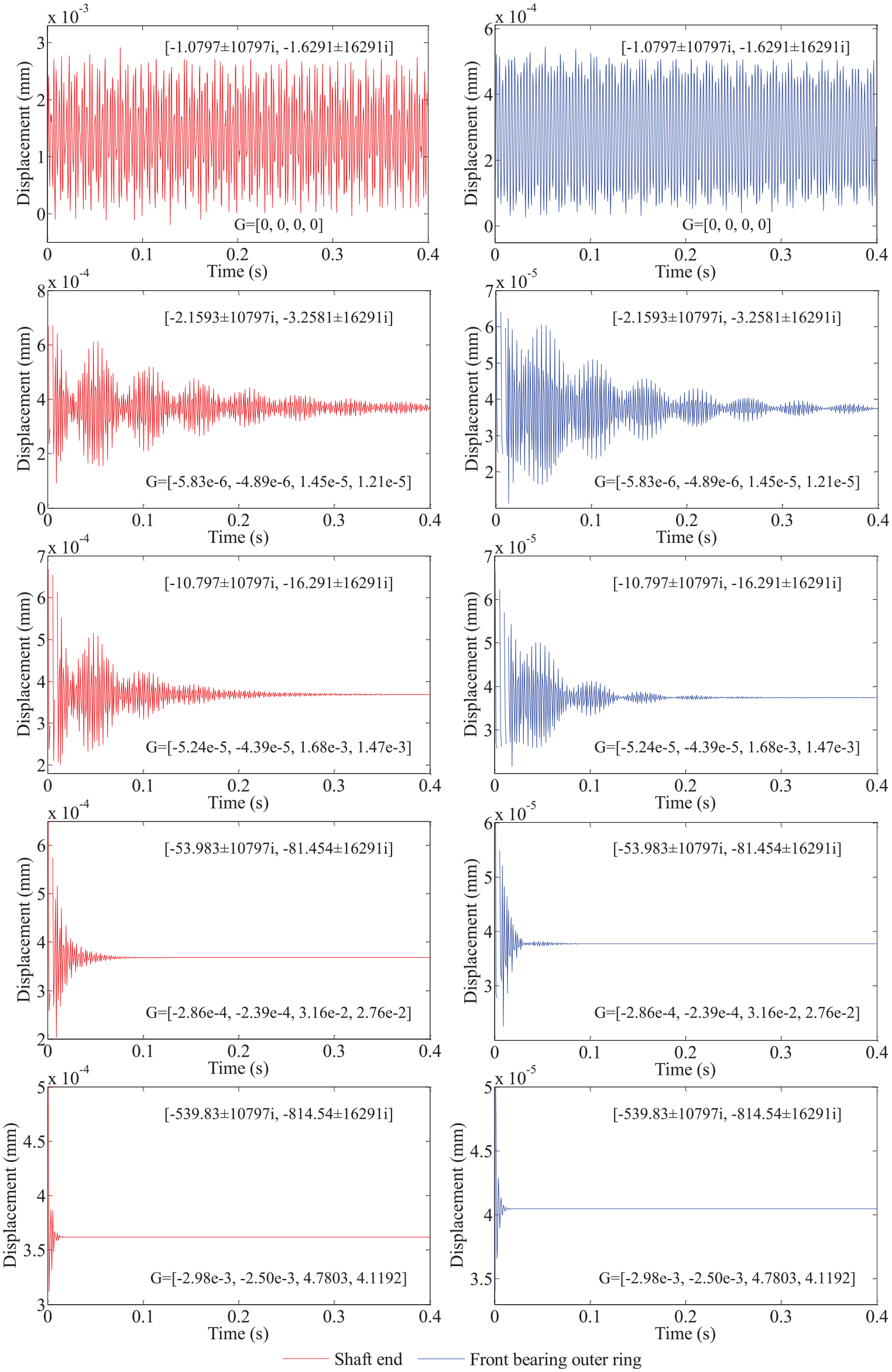
Displacement responses at the shaft end and front bearing outer ring with different eigenvalues and gain matrix in one of the orthogonal directions at 5000 r/min.
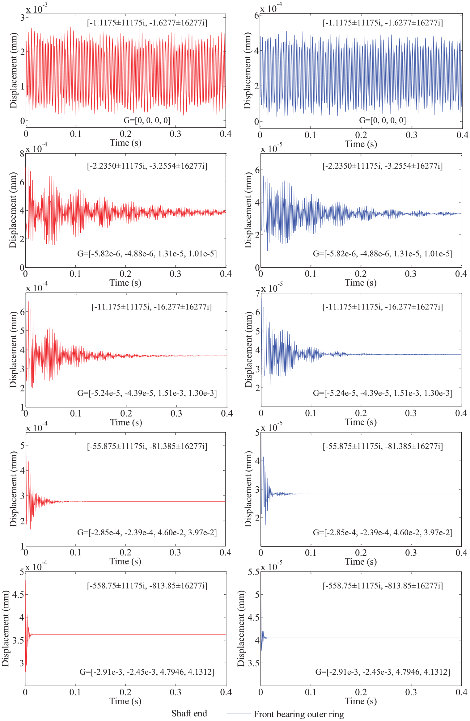
Displacement responses at the shaft end and front bearing outer ring with different eigenvalues and gain matrix in one of the orthogonal directions at 10,000 r/min.
The condition numbers of eigenmatrix, which is the measurement of the robustness of system, are shown in Table 4 (5000 r/min) and Table 5 (10,000 r/min). With the increase in the absolute value of the real parts of desired close-loop eigenvalues, the condition numbers of eigenmatrix derived from the robust eigenvalue placement method increase, which indicates that this method leads to poor robustness of system and weakens the adaptability of system to model error and uncertain factors. While compared with Ackermann’s eigenvalue placement method, 26 the condition numbers derived from the robust method are smaller. Therefore, the robust eigenvalue placement method can ensure the excellent robustness of system in active vibration control, which refutes the conclusion drawn by Palazzolo et al. 20 and proves that the accuracy of the system model determines the control design and response analysis. When the close-loop eigenvalues are −539.83 ± 10797i, −814.54 ± 16291i (5000 r/min) and −558.75 ± 11175i, −813.85 ± 16277i (10,000 r/min), and the condition numbers of eigenmatrix are 1.8466e+004 (robust method at 5000 r/min) and 1.9003e+004 (robust method at 10,000 r/min), which are so large that the robustness get worse seriously compared with the open-loop system. Meanwhile, this situation needs lots of control energy. So they will not be accepted.
The gain matrices and condition numbers of close-loop eigenmatrix with different eigenvalues placement at 10,000 r/min.
Conclusion
This paper deals with the problem of active vibration control for a rotor-bearing-actuator system using robust eigenvalue placement method. The model of the rotor-bearing-actuator system is proposed, and the robust eigenvalue placement method for control design is applied on the system. From the simulation results, the following conclusions can be drawn:
The accuracy of the system model determines the control design and response analysis.
The robust eigenvalue placement method can place the eigenvalues to desired positions, and the system can have a high stability. The displacement responses at the shaft end and front bearing outer ring can decay rapidly under a step-input load, which indicates that this method is effective for active vibration control of a rotary machine.
Although the condition number of close-loop eigenmatrix will decrease, compared with the open-loop system, the robust eigenvalue placement method can get a smaller condition number than Ackermann’s method which means that the system has a better robustness.
Footnotes
Declaration of conflicting interests
The author(s) declared no potential conflicts of interest with respect to the research, authorship, and/or publication of this article.
Funding
The author(s) disclosed receipt of the following financial support for the research, authorship, and/or publication of this article: This work is financially supported by National Natural Science Foundation of China. (No. 51405151).