
Abstract
Even if there exists remarkable applications of induction machines in variable speed drives and also in speed sensorless control in the low–high speed region, open/closed loop estimators in the literature utilized on induction machine sensorless position control vary regarding to their accuracies, sensitivity, and robustness with respect to the variation of model parameter. The deterioration of dynamic performance depends on the lack of estimation techniques which provide trustable information on the flux or speed/position over a wide speed range. An effective estimator should handle the high number of parameter and model uncertainties inherent to induction machines and also torque ripple, the compensation of which is crucial for a satisfactory decoupling and linearizing control to provide the accuracy and precision requirements of demanding motion control in the field of robotics/unmanned vehicle. In this study, to address all of the above-mentioned problems, robust-adaptive linearizing schemes for the sensorless position control of induction machines based on high-order sliding modes and robust differentiators to improve performance were designed. The control schemes based on direct vector control and direct torque control are capable of torque ripple attenuation taking both space and current harmonics into account. The simulation results comprise both the estimation and sensorless speed control of induction machines over a wide operation range, especially at low and zero speed, all of which are promising and indicate significant superiority over existing solutions in the literature for the high precision, direct-drive, speed/position sensorless control of squirrel-cage induction machines.
Keywords
Introduction
Since induction machines (IM) have highly nonlinear and coupled fifth-order dynamics under strong parameter and model uncertainties and make it possible to measure only three state variables, linearizing and decoupling control of IMs is a competitive problem in nonlinear control field. The breakthrough in the control of IMs has been achieved after the invention of field-oriented control (FOC) or vector control (VC). 1 By applying VC method to the IM, speed and torque control become easier. To develop such kind of scheme, stator or rotor flux magnitude and their angles relative to the stationary stator should be accessible through a sensor measurement or an observer estimation. A large number of researches have conducted for implementing FOC approach, which transforms the IM’s control to that of a separately excited direct-current (DC) motor by setting the rotor flux constant on the direct axis. Nonlinear into linear system conversion is possible with this approach, which helps to decouple the flux and speed (or position). Unfortunately, the assumption of a constant rotor flux gives rise to an only “asymptotically” decoupled or input–output (I-O) linearized system. To cope with this kind of problem, I-O linearization methods have been studied. These methods utilize the flux dynamics,2–5 or dynamic I-O linearization with the addition of an integrator.6,7 In Khorrami et al., 8 nonsingularity conditions on the direct-quadrature (d-q) model, when the position is also added as output, have been investigated. The feedback linearization (FL) performance is influenced by the system parameters, which vary with the operating conditions. Besides the load changing from low to high, inductances are likely to saturate at high flux levels and resistances are inclined to increase as a result of temperature which is particularly effective for the stator resistance and frequency, showing itself mostly on the rotor resistances as skin effect. The parameter uncertainties which are dealt by some studies9–11 are as follows: addressing and modeling magnetic saturation effects,12,13 taking an adaptive approach for the compensation of the rotor resistance and external load,14,15 developing an adaptive nonlinear feedback for torque control, 16 estimating and compensating the saturation effect, 17 proposing a robust dynamic I-O linearization scheme for rotor resistance variations, 18 developing an adaptive method against rotor resistance/load variations, and, finally, 19 developing a parallel model reference adaptive scheme (MRAS) to compensate for the variations of the rotor and stator resistances. Since the overall performance of the VC depends on the uncertainties of unpredictable parameter variations of the system, external load disturbances, unmodeled and nonlinear plant dynamics, all the above-mentioned methods require flux observers, the performance of which also depends on how well the system parameters are accessible. An observer-based solution coping with the problem of parameter variations could be given as follows: in Alagna et al., 20 a sliding mode flux observer was designed to estimate the rotor flux vector for improving the performance of the sliding mode–based torque control while sustaining robustness against change in load torque and parameter variations; in Stumper and Kennel, 21 a nonlinear observer structure, which operates at any speed, in extremely low and zero speed up to half nominal torque, with direct FOC, was proposed to estimate the motor speed and the rotor flux; in Luo and Ke, 22 a full-order flux-observer-based speed estimation approach with an MRAS identifying the stator resistance parameter was applied to realize a rotor flux-based VC of an IM drive. Model uncertainties and nonlinearities inherent to IMs are well suited for the stochastic nature of extended Kalman filters (EKFs). 23 Through the help of this method, online estimation of states can be made while identifying parameters in a relatively short time interval by taking system/process and measurement errors (noises) directly into account.24–26 Passivity-based approaches,27–29 which also depend on accurate knowledge of parameters, robust control, 30 and intelligent control approaches 31 against parameter uncertainties were also utilized for IM control. Both FOC and DTC (direct torque control) drives necessitate robust (to parameter and model uncertainties) and speed sensorless solutions. In industrial applications, low-cost and precise speed sensorless systems able to effectively drive IMs at low and zero speed are preferable. 32 If one can eliminate the speed sensor at machine shaft without deteriorating the dynamic performance of the drive control system, the following benefits are provided: economy on both cost and size, elimination of additional wiring, drift and noisy measurements, and reduced hardware complexity. To eliminate speed or position sensors, an observer, which estimates position or speed values from measured stator voltages and currents, can be used. This procedure leads to speed/position estimation schemes, which deal with the effect of parameterization errors and model/load uncertainties. Speed/position sensorless control of IMs constitutes a problem of specific nature at very low speeds and specifically at zero speed. As the electromagnetic field maintains a fixed position in space at this operating point, the rotor-induced voltages in the stator windings have zero values. This gives rise to problems in the spatial orientation estimation of the rotor field based on measurable quantities, such as currents and voltages on the stator side. 33 To obtain successful results, not only robustness against parameter and model uncertainties should be satisfied but also solutions must be sought in the very low-speed region, specifically at zero speed under full load and no load (at zero stator frequency) in the designed observer methods. 34 Much research are titled “model-based” in that they use two-axes machine model to predict the speed and a flux angle necessitating for a high-performance vector drive.35–38 The speed estimation below 1 Hz machine frequencies, model-based approaches do not provide remarkable performance and improvements in the online parameter estimation are not satisfactory. Tracking saliencies within an IM based on high-frequency (hf) signal injection is another method realized in the literature. This method can yield either the rotor position or an orientation flux angle without needing to a machine model39–43 and thereby demands to solve the zero- and low-speed cases. These methods comprise two categories. The first one is related to the natural saturation saliency, which yields an orientation flux angle . 44 Unfortunately, phases among the saturation vector and either flux vector (stator or rotor) are affected from the leakage saturation and slot design.45,46 This kind of dependency cannot be acquired from the two-axes machine model knowledge; therefore, modeling based on finite-element method or experimental research is necessitated to quantify it. Saturation saliency tracking can be applied to a torque-controlled drive; however, a model-based speed estimator should be used for speed control. A rotor saliency arising from rotor slotting or a saliency involving circumferential variation of surface rotor resistance 47 or leakage inductance 48 is tracked in the second category. 49 Rotor position is estimated to be used for sensorless position control and field orientation through VC techniques. The saturation saliency modulation of the hf stator currents interferes with the rotor saliency modulation in a fully fluxed machine and machine under load. Owing to the variable magnetic coupling among the discrete rotor bars and stator windings of an IM, a quasi-continuous rotor position signal is obtained measuring three-phase stator leakage inductance. The sampling process is conducted synchronously through the regular commutations of the pulse width modulation (PWM); thus, the injection of additional hf carriers is unnecessary. The acquired signals exhibit high spatial resolution and dynamic bandwidth. The repetitive transient excitation through the test signals was made to identify the spatial orientation of anisotropies that indicate the rotor position. The position information is contained in the inverter output voltages. These are measured against the neutral point of the star-connected stator winding. The disturbance for position identification is constituted due to the effect of the magnetic saturation upon the total leakage inductances. Two different approaches relying on anisotropy effects, the frequency-domain approach50,51 and the time-domain approach, 52 were applied to estimate the rotor position angle. A transient condition by continuously injecting an hf carrier signal into the stator windings is established by the frequency-domain approach. These anisotropies are linked to spatial orientation of angular position of the rotating fundamental field. The directions in space of such anisotropies are detected from the machine response to perpetuate transient excitation through stator windings. The position information, which is acquired by phase-locked loop (PLL) technique, is mirrored in the negative sequence response signal component. The inverter dead-time phenomena, parameter dependence, low signal-to-noise ratio (SNR), the dynamic delay of the PLL, and magnetic saturation effects are unwanted effects in the estimation technique for fully loaded closed-loop position control system. 53 In the time-domain approach, instantaneous samples are collected from the stator phase voltages, immediately after the inverter commutations at PWM operation. Inverters, which are switching higher transient excitation than a continuous carrier injection give rise to a high SNR. The zero sequence voltage component, which is computed using the sampled stator phase voltage, demonstrates an imbalance at the sampling instant among total leakage inductances of three phases. Such imbalance originates from the variation of the magnetic coupling among the rotor bars and stator windings, magnetic coupling degree.
To improve the parameter sensitivity, open-loop estimators or closed-loop observers have been constructed for the estimation of velocity and flux. A variety of approaches have been taken for this purpose, some performing state estimation only and some also performing load and/or parameter estimation. Various problems have been encountered in the process, that is, simultaneous estimation of the rotor and stator resistances gives rise to instability 54 and inaccurate rotor and stator resistance estimations. 55 Model reference adaptive laws 56 estimate the flux and speed; however, the system response is not tested for load torque variations. Rodič et al.’s study 57 uses sliding mode observers (SMOs), while Mehta et al.’s study 58 develops Gopinath’s reduced-order observer. Zaky 59 develops an adaptive flux observer (AFO) using the Lyapunov and Popov criteria, respectively, and requires adjustments to the observer gain matrix with changing operating conditions to suppress the oscillations on the estimated velocity. In the speed sensorless study, 60 in which the stator resistance has been estimated based on a two-timescale approach, it has been stated that even a very small offset in either the voltage or the current measurement causes instability of the drive at zero stator frequency and rated load. SMOs, as in Umida and Guidi 61 and Edwards et al., 62 have also been designed with the error correction term reflected to the observer as a multiplicative term. Theoretically, the switching frequency should be infinite to avoid chattering on the sliding surface, 63 which poses problems in some applications. In Lascu et al.’s study, 64 a DTC-based on an SMO using a dual reference frame motor model was achieved at very-low-speed sensorless operation. The performance was obtained without using hf signal injection or saliency effects for the flux and speed estimation. Gaballah et al. 65 present a chattering-free SMO, whose switching function is replaced by a rule-based fuzzy logic system, for the velocity with high-accuracy tracking performance. Unlike adaptive methods, which require persistently exciting input signals, EKF uses the above-mentioned system noise to fulfill the hf signal requirement for accurate and fast convergence. This feature also makes EKF an attractive option in the sensorless control of IMs, despite of its computational complexity. Among studies related to the EKF estimation for IMs, Mannan et al. 66 and Hinkkanen 67 estimate the velocity and flux with full-order observers, while Zaky 68 uses an adaptive flux-observer insensitive to stator resistance variations. In addition, in sensorless control, the velocity is estimated as a constant parameter, with the assumption of slow variation. However, the estimation performance at very low- and zero-speed region is not satisfactory. A Luenberger observer in Jouili et al. 69 was designed for velocity estimation, but very low- and zero-speed operation has not been addressed. For improved performance against the problems of sensorless control in the very low- or zero-speed region, methods have been proposed that make use of magnetic or electrical anisotropies of the rotor for the determination of the rotor position. 70
Two approaches are taken in the literature: frequency-domain approach based on the injection of hf signals, a major disadvantage being the demand for additional hf signals, sensitive to system parameters, the dynamic delay originated from PLL, low SNR, and magnetic saturation due to the fundamental field; and time-domain approach, making use of the inverter PWM signals, which provide a high SNR. The latter approach is quite effective for the control of IMs (in the very low- and zero-speed region); however, problems arise due to signal acquisition in the high-speed region—therefore, special measures (such as the use of a different model) must be taken when it is aimed to perform velocity control over a wide speed range. This issue was addressed by taking the angular velocity into consideration via the equation of motion in an EKF scheme that also estimates the load torque and rotor resistance. The torque term in the equation of motion helps conveying the rotor information to the stator side, which is otherwise lost at zero stator frequency. The approach has yielded successful results over a wide velocity range, also including very low and zero speed.71–73 Finally, another factor to consider for precise position control in IMs is the torque pulsations caused by the interaction of the space harmonics of the motor and the current harmonics. Those pulsations, also known as torque ripple, affect the position output significantly and are unacceptable for high-performance motion control and robotics applications. Therefore, to establish the compatibility of IMs with high-cost, high-performance motors for those applications, solutions must also be sought for torque ripple minimization. There have been numerous studies on the modeling of torque ripple74,75 for IMs, but studies dealing with the elimination of torque ripple are mostly related to DTC only, which inherently has the drawback of high torque ripple due to variable switching frequency, for example, Toro et al. 76 address the problem of current harmonics only by different switching strategies for DTC, that is, by using space vector method (SVM). Studies also corresponding to the effects of space harmonics are very rare, such as Vernet et al., 77 which uses a Kalman filter to estimate the two components of the harmonic rotor flux generated by one space harmonic for wound rotor IMs but has a speed sensor. To summarize the results of our review of existing literature on IM control, it has been noted that successful examples of sensorless IM speed control in the very low- and zero-speed range and similarly sensorless IM position control are very rare.78–80 Those solutions mostly require extra precautions for signal acquisition and/or address low-speed operation only. However, high-performance position control also requires a good transient performance, calling for improved estimation/control methods over a wide speed range.
In this paper, computer simulations related to the robust-adaptive linearizing schemes based on higher order sliding-mode controllers (HOSMC) were conducted for DTC. It is intended to contribute significantly to the challenging area of sensorless position control of IMs with novel control and observer schemes that are specifically designed to solve the major problems encountered in the high-performance control of IMs. The outcomes will also contribute significantly to the IM position/tracking control with sensors, as well as sensorless speed control in a wide speed range, including very low/zero speed. Most studies in the literature address only certain subsets of IM control problems. However, for the IMs to be compatible with their more expensive counterparts in high-performance motion control, all of the above-mentioned problems should be solved. In this paper, the following approaches are proposed for this purpose:
A multiple EKF-based observer approach for the online estimation of a high number of parameters and states. The proposed estimation scheme meets the parameter/state requirements of the observer scheme as well as those of the linearizing and decoupling controllers.
HOSMC-based robust-adaptive linearization schemes for increased robustness and accuracy.
A torque ripple cancelation approach for FOC and DTC schemes, with the consideration of both space and current harmonics. Modeling of torque ripple in IMs has been frequently addressed, but its minimization is mostly addressed for DTC and by reducing the current harmonics only.
The contributions of this paper are not limited to IM applications; for example, the proposed observer could be used with any nonlinear control system requiring the reliable estimation of a high number of state/parameters. Similarly, the proposed continuous HOSMC and adaptive torque ripple minimization schemes could address robustness and accuracy problems in a variety of electromechanical systems.
IM model
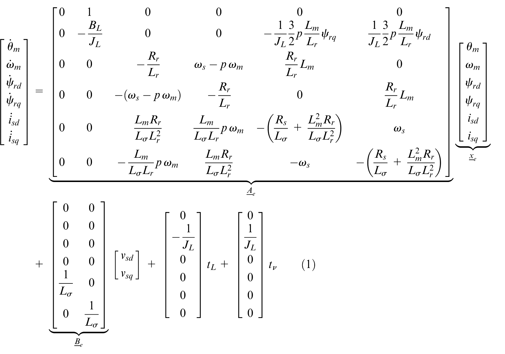
Before constructing control/observer schemes, the mathematical model of IM is derived in d-q axis, with the inclusion of the motor angular position—with the definition of
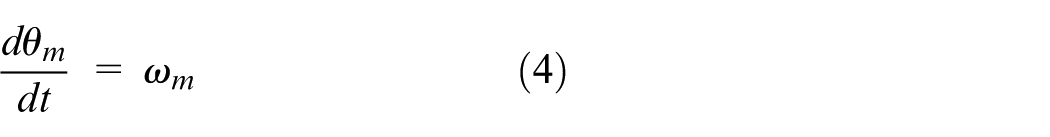
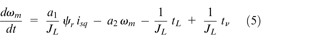
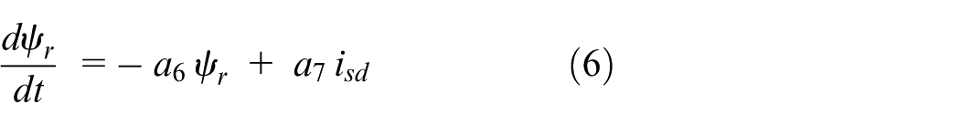
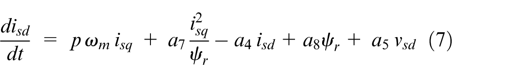
The state-space form of the IM model is given in equation (1)
The d-q axis angular velocity can be represented in terms of electrical parameters as in equation (2)
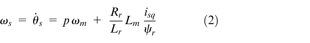
where
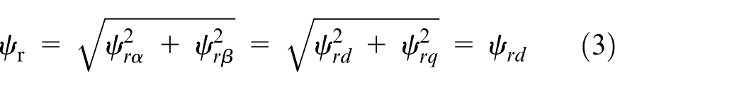
The magnitude of the rotor flux is defined as in equation (3)
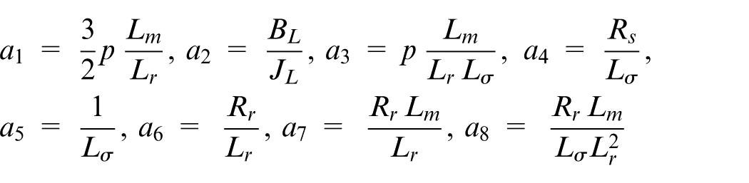
For further simplification, the following definitions are made for the parameters
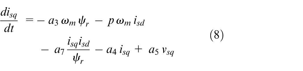
All parameters are assumed to vary slower than the states, and hence, their time derivatives are taken as zero. Under the assumption of a good control for
The system outputs are chosen as in equation (9)

In the “Control strategies” section, different control strategies are proposed to achieve I-O linearization for the VC and DTC of IMs.
Control strategies
Robust-adaptive linearizing controller based on HOSMC for VC
An HOSMC-based adaptive linearizing control is explained for both vsq and vsd. Two HOSMC approaches will be taken as follows:
HOSMC with discontinuous input, which depends on the artificial increase of the system order, to reduce chattering effects on the output for increased accuracy.
HOSMC scheme with continuous input to avoid the requirement of high-order state derivatives due to the artificial order increase.
The parameter and state estimation required for linearization and decoupling should be provided by an observer scheme. The HOSMC is designed to provide robustness against uncanceled nonlinearities as well as the torque ripple effects, which are not taken into consideration for direct cancelation in this scheme. HOSMC has proven to be very effective particularly against load uncertainties as well as low-order torque ripple terms, which tend to be the more effective in electric motors. 81
Defining the outputs as


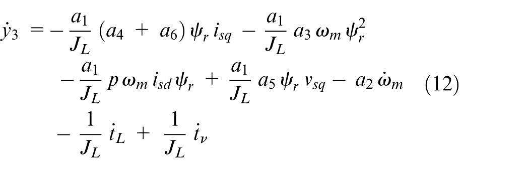

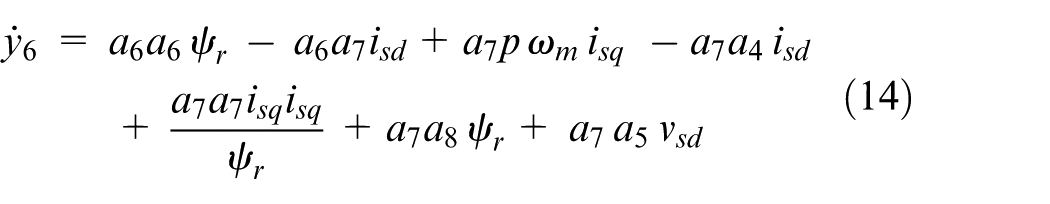
The nonlinear terms given in equations (12) and (14) are simplified by defining new control inputs as in equations (15) and (16)
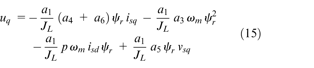
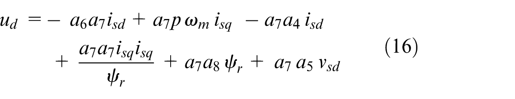
Using equations (15) and (16)—
The control inputs applied to the motor are represented as in equations (18) and (19)
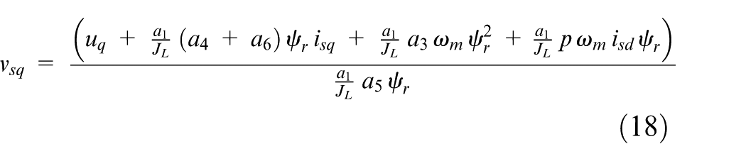
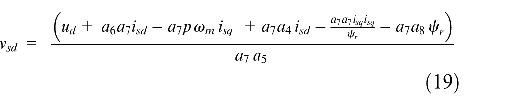
As can be easily seen from equations (18) and (19), the system is not state-input linearizable. In addition, it must be ensured that
Derivation of uq for position control
For position control, the relative degree is 4, and hence, a 4-HOSMC is proposed for position control82–84 for avoiding the chattering effect from the control input. For 4-HOSMC, the error dynamics become

where
Derivation of ud for flux control
For flux control, the relative degree is 3, and hence, a 3-HOSMC is proposed considering the error dynamics as

where
Disturbance effect, unmodeled dynamics, torque ripples and remaining nonlinear terms after linearization will be eliminated by the HOSMC controllers. To apply this controller, one needs information on the following variables:
Robust-adaptive FL approach with torque ripple minimization for VC
In this section, a robust-adaptive feedback linearizing scheme was implemented for the position tracking control of IMs with torque ripple minimization via the q-axis current. The adaptive I-O linearizing inner loop was designed for the cancelation of torque ripple terms and can be augmented for the cancelation of sinusoidal or constant load terms (including constant friction). As the robust outer loop, it was designed an HOSMC scheme with continuous input to avoid the calculation of high-order derivatives. To eliminate the torque ripple, the frequencies of the most significant components were determined with a self-commissioning scheme with the unknown amplitudes calculated by parameter adaptation.
For the design of the control law, the q-axis current component, equation (5) is written as in equation (22)
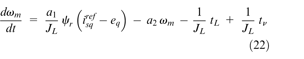
where
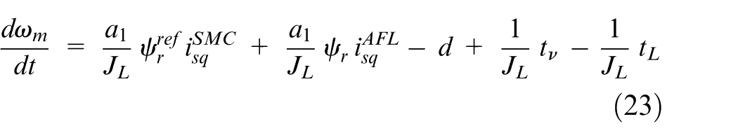
Equation (22) is transformed into equation (23)
Taking
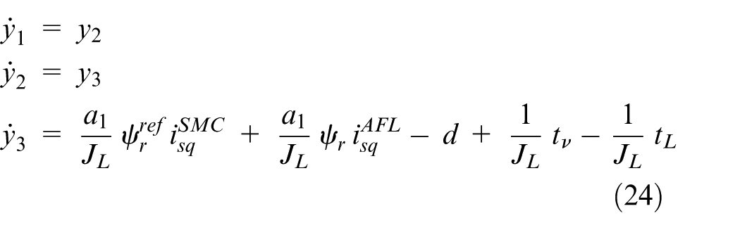
where
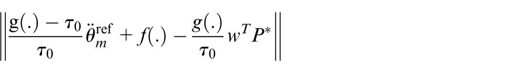
An HOSMC-based robust outer loop for position control is derived as a novel chattering-free HOSMC with continuous input based on the Lyapunov approach as in equation (25)
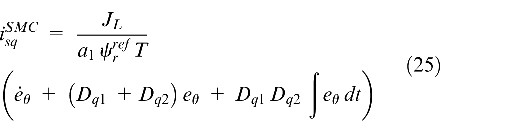
where
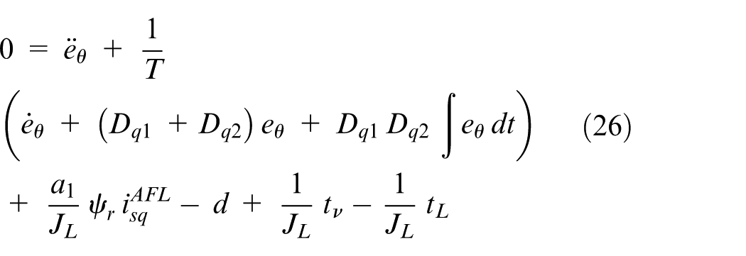
An adaptive linearization scheme was designed to suppress sinusoidal and/or constant load terms “
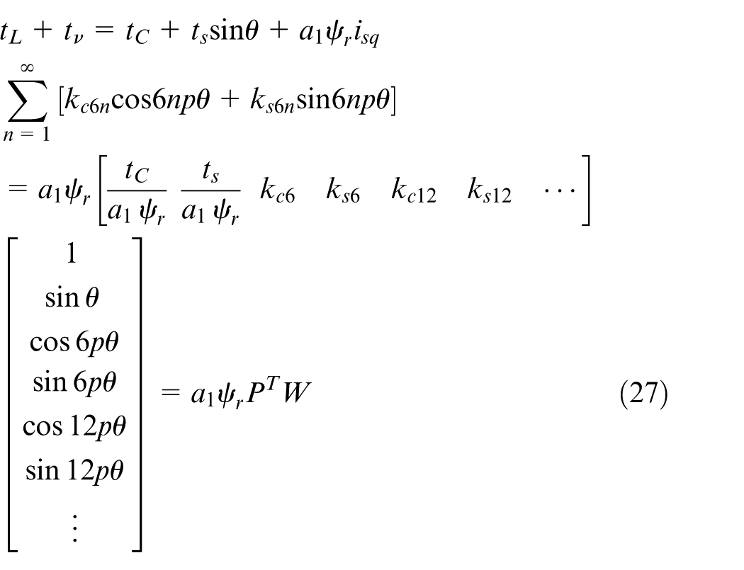
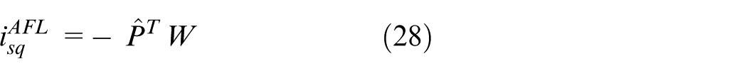
The control input,
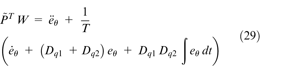
Substituting equations (27) and (28) into equation (26), the error dynamic becomes as in equation (29)
For the update law of parameters, a Lyapunov function is chosen as in equation (30)
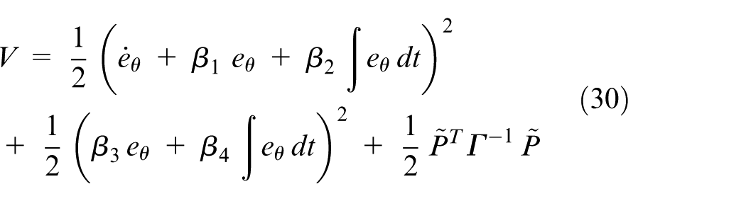
where
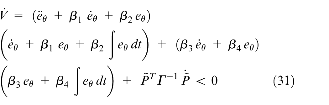
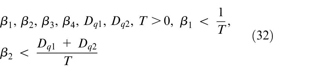
The negative definites can be ensured by fulfilling the following equalities and inequalities given in equations (32) to (34).
Inequality conditions
Equality conditions
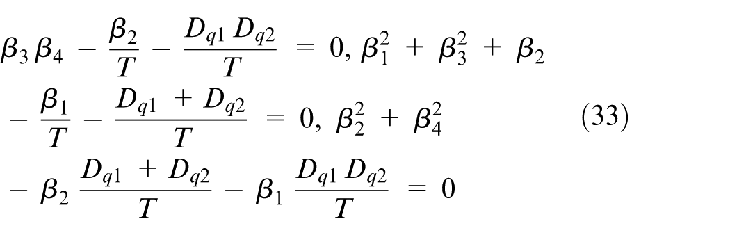
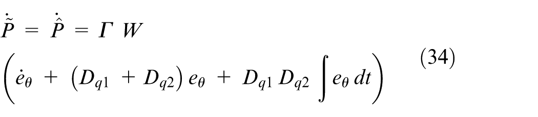
Equation (34) also gives the parameter adaptation rules. Now that the
A chattering-free 3-HOSMC with discontinuous input for flux control shares the same structure represented in equation (21). The artificial input
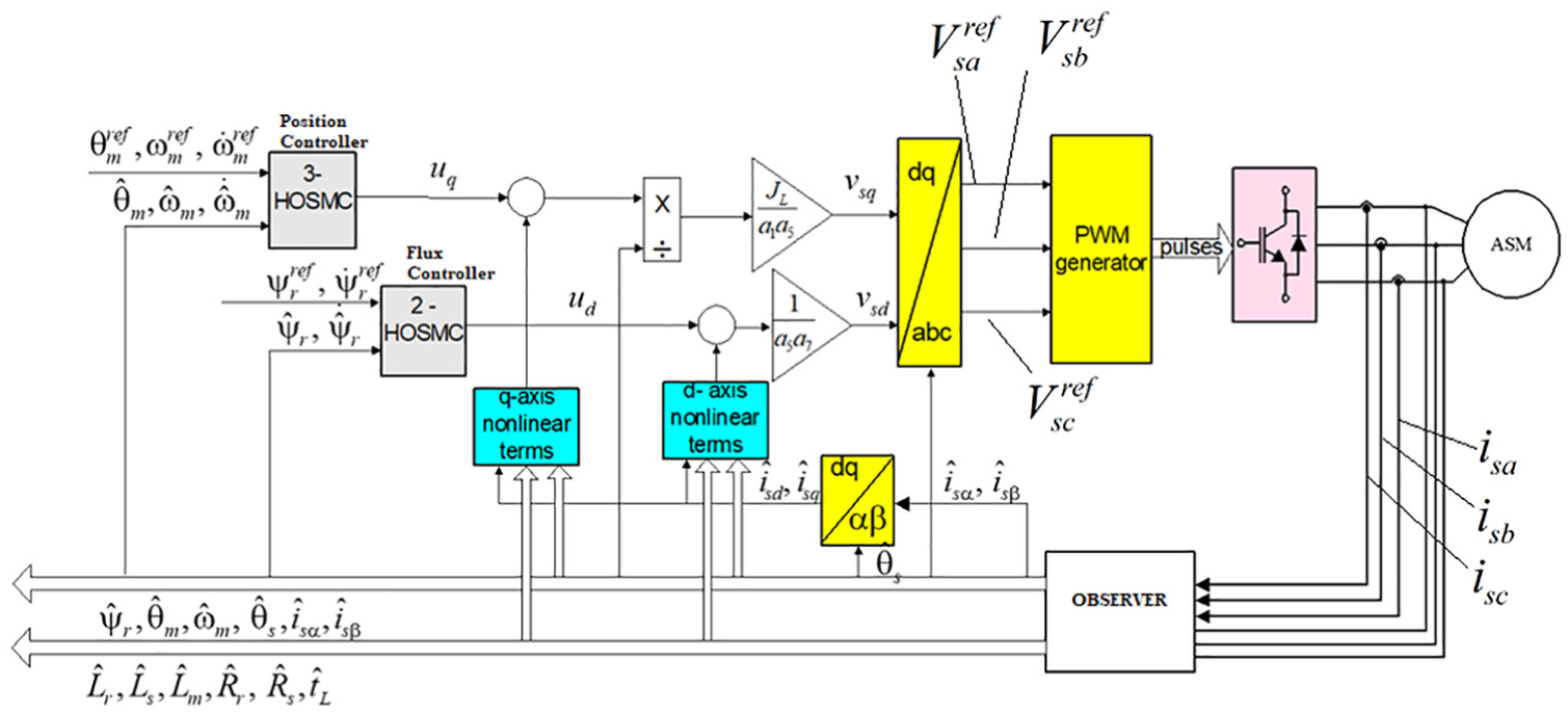
System control block scheme for robust control of IM.
Robust-adaptive FL approach with torque ripple minimization for DTC
Fast torque and flux responses can be obtained with DTC, which requires the flux magnitude, flux angle, and torque variations. Observers deliver the information required by the control system. A robust-adaptive FL scheme with constant switching frequency to avoid extra harmonic components caused by variable switching frequency was designed. The functional block diagram for the whole system is given in Figure 2.
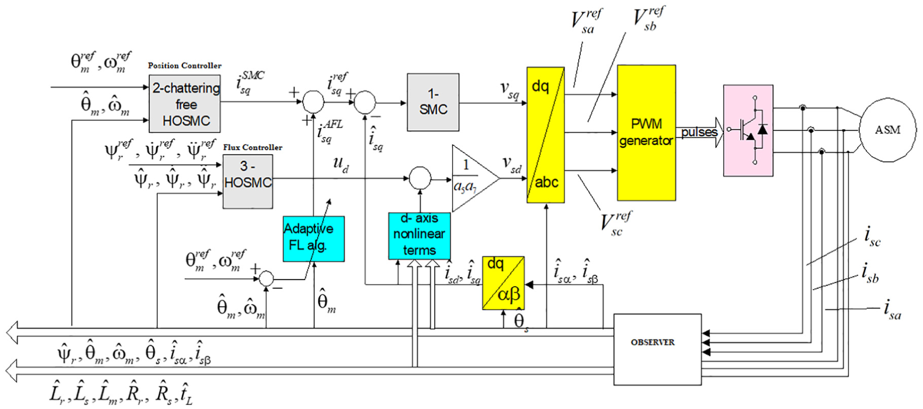
System control block scheme for robust-adaptive linearization IM.
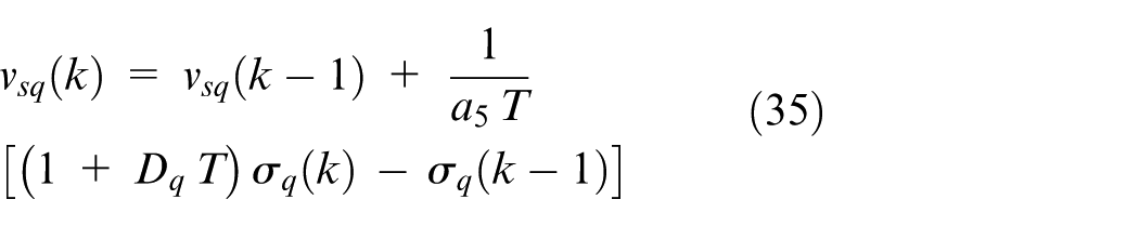
For this purpose, the d-q model is organized with motor torque as a state variable in equation (36)
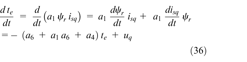
with definitions, such as
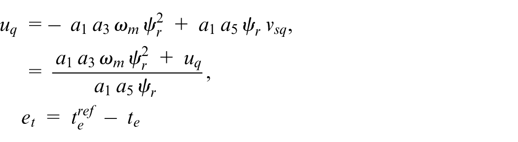
The following equations are obtained as in equations (37) to (39)
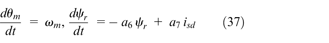
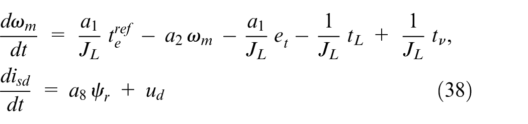
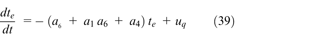
Here,
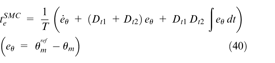
The adaptive linearizing term is
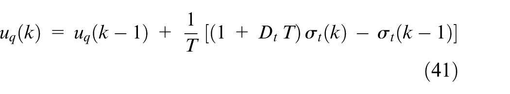
By choosing the sliding mode as
Multiple EKF-based observer
An EKF-based observer scheme was designed for the estimation of high number of parameters and states required by I-O linearization. The IM model depends on six parameters: (
The structure and block scheme of the multiple EKF algorithm were demonstrated in Figure 3(a) and (b), respectively.
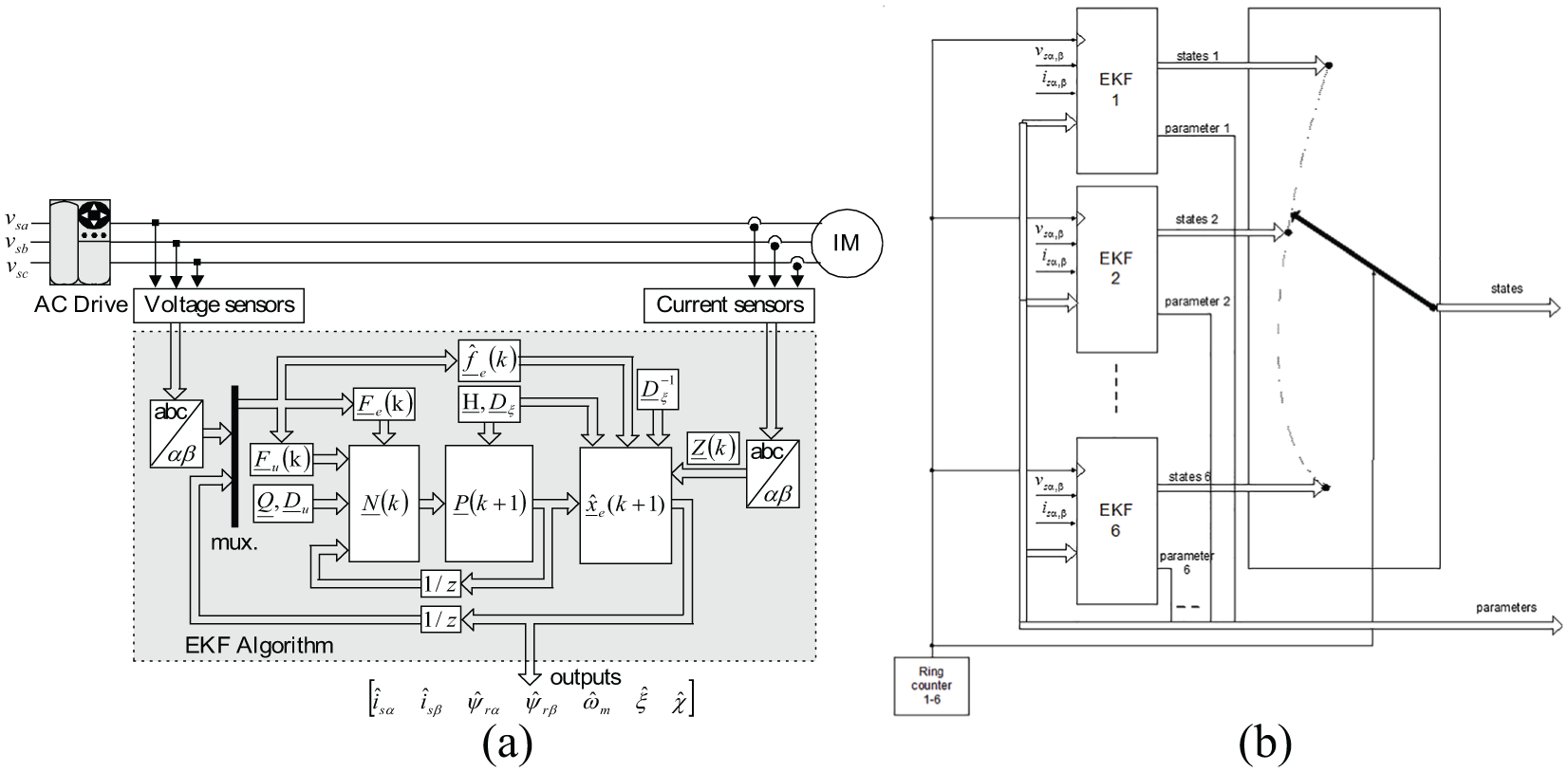
(a) Structure of the EKF algorithm and (b) multiple EKF algorithm block scheme.
Multiple EKF-based sensorless DTC
The sensorless DTC scheme developed for IM requires the estimation of stator flux components (
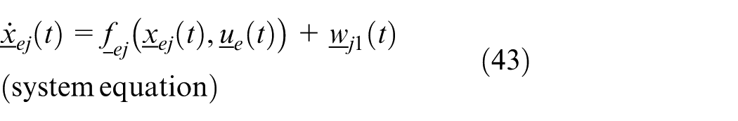
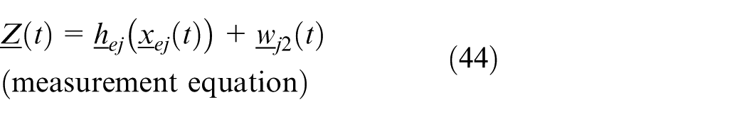
Here, “j = r or s” (based on whether the extended model has
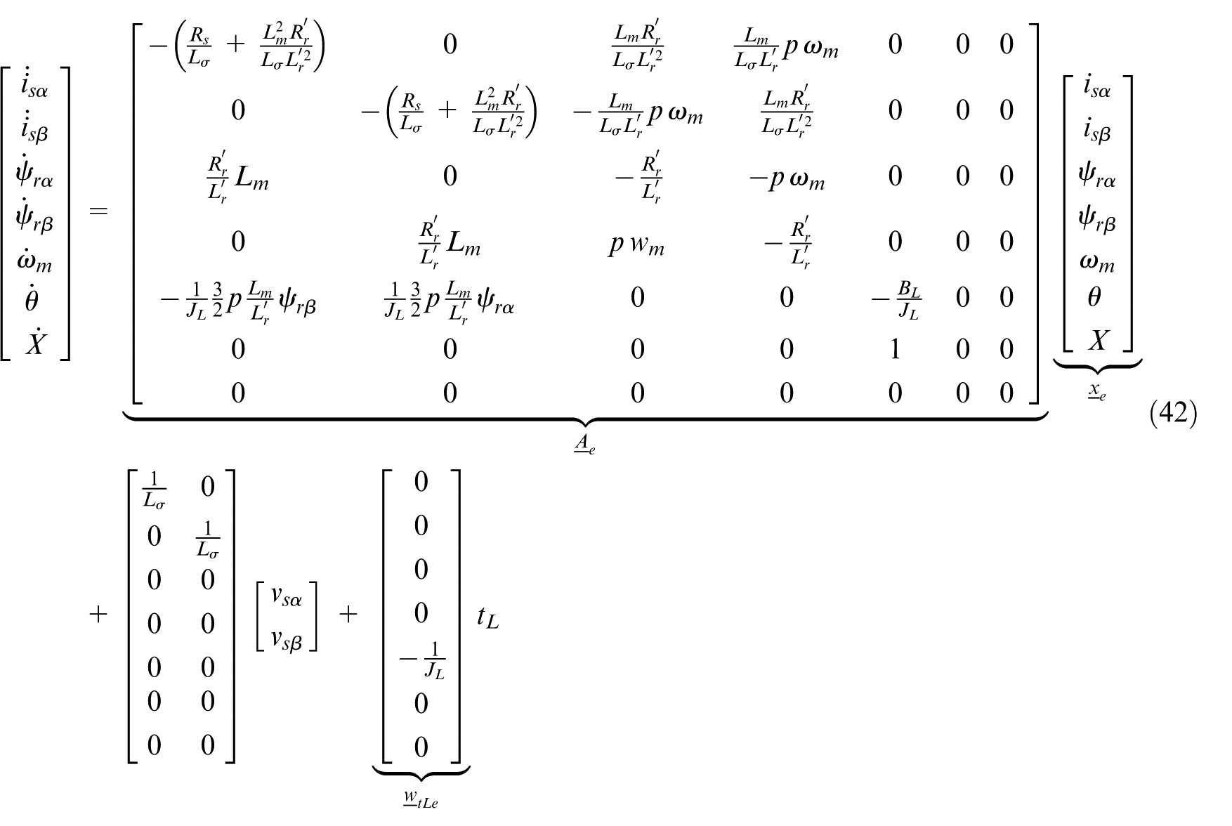
Based on those assumptions, system model can be given as in equation (45)
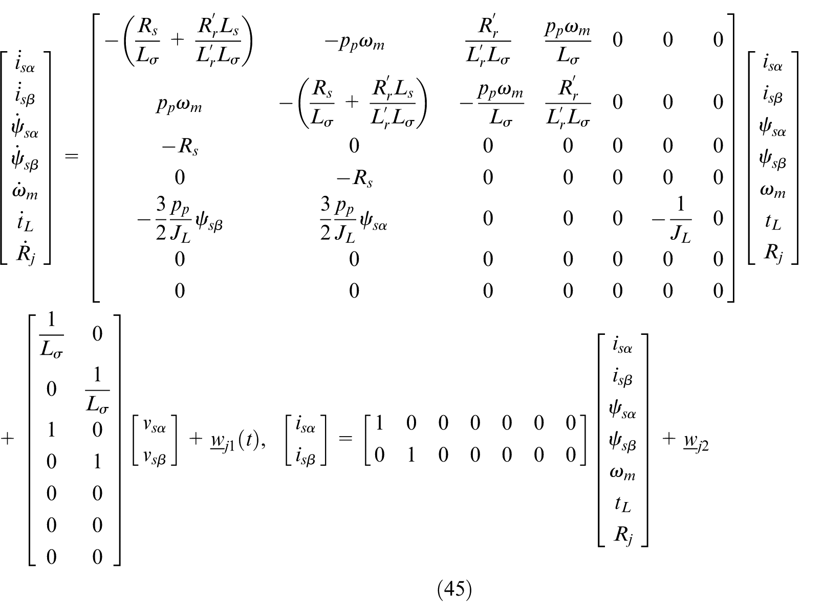
Here,
EKF-based estimator for the speed sensorless VC
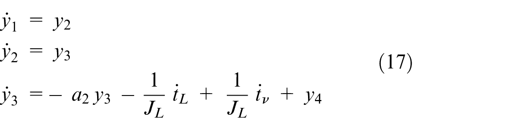
EKF-based algorithms are developed for the speed sensorless FOC and DTC of IMs. The algorithms are designed aiming minimum estimation error over a wide velocity range, including very low- and long-duration zero-speed operation. A major challenge at very low and zero speed is the lost coupling effect from the rotor to the stator, which makes the rotor angular velocity unobservable on the stator side. The state-space representation of the model is derived as in equation (46)
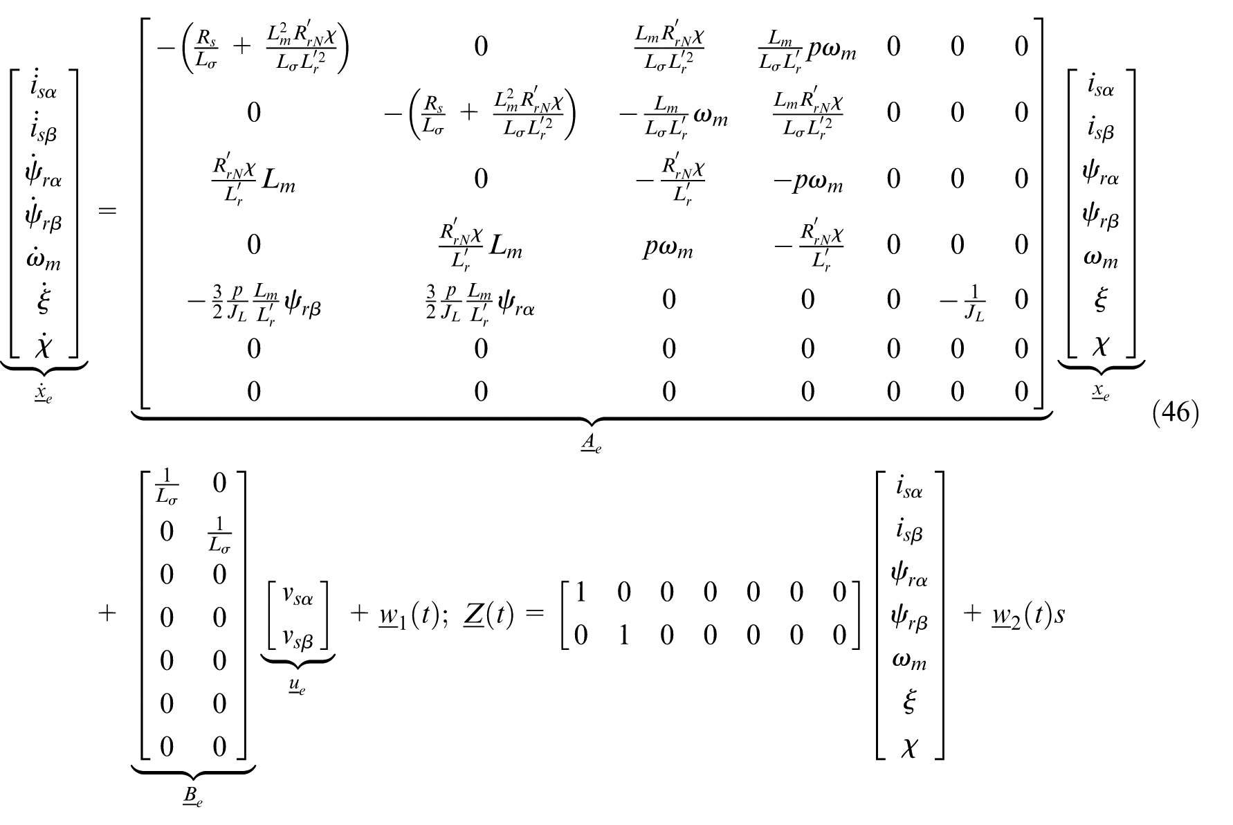
where
The simultaneous estimation of the rotor angular velocity and load torque is performed with the velocity taken into consideration and not as a constant parameter. The load torque estimation is performed as a constant parameter to evaluate Coulomb and viscous friction at steady state for enhancing the performance at very low and zero speed. The algorithms based on the rotor and stator flux are conducted under variations and reversals of the velocity and load torque over a wide velocity range and at zero speed. In all scenarios, the current estimation error has stayed within a low error regime, while satisfactory and many times, lower velocity estimation errors have been acquired over a wide velocity range and at zero speed. The control algorithm of the speed sensorless DTC was given in Figure 4.
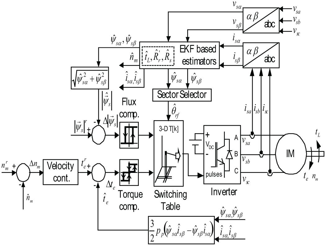
Speed sensorless DTC.
There are some studies done in the literature86–91 to design tuning rules for Q (process noise covariance matrix) and R (measurement noise covariance matrix). The sensitivity of the covariance matrix Q is bigger than R with respect to convergence and stability. If Q is increased irresponsibly, this means the system noise and parametric uncertainties are high. Therefore, the filter gain also rises and results in rapid but high response and fluctuations. If Q is decreased, this will lead to a weaker correction and state estimation. When R is increased, the measurements are sensitive to noise and should be weighted less by filter. This causes smaller filter gain and slower transient response. In this study, by considering these facts and making some trial-and-error research, the matrices were selected as
“diag” refers to a diagonal matrix.
Stability and robustness analysis of the system
Exponential stability of the system
Adaptive systems are not robust to modeling error and parameter uncertainties. Robust stability can be guaranteed if the persistency of excitation of regressor is satisfied. The regressor functions in the induction motor control situation are continuous, periodic, and bounded. Therefore, it is possible to determine the conditions on exogenous signals for ensuring the persistency of excitation. 92
In this section, the conditions on exogenous signals that ensure the persistency of excitation originating from the specific structure of the motor dynamics are determined, although it is not possible to find these conditions for general nonlinear systems.
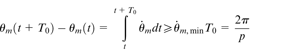
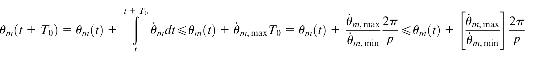
Guaranteed minimum speed
Given
Motor persistency of excitation
If
A vector-valued function
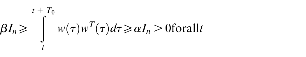
The existence of
Choose
Then
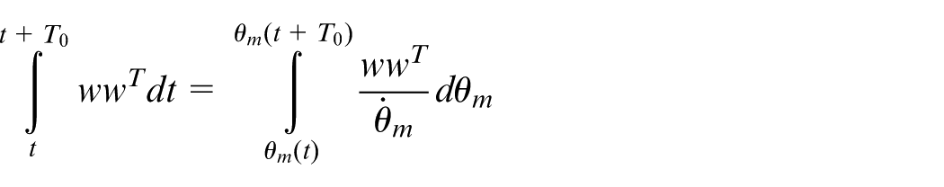
Since
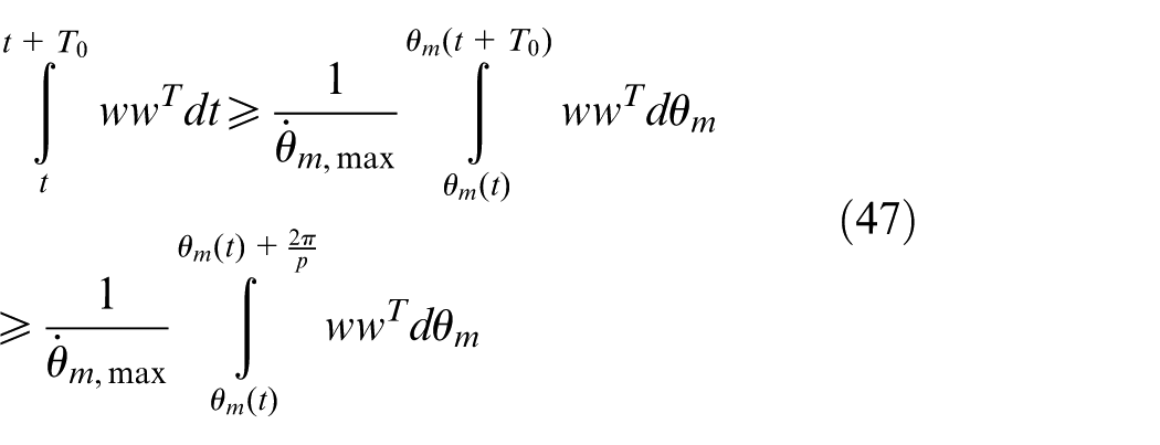
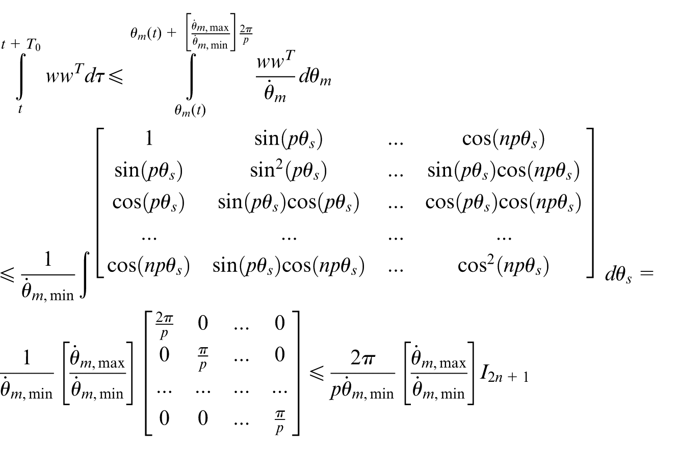
where equation (47) is based on the facts that
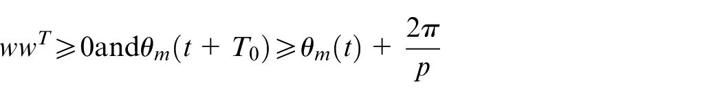
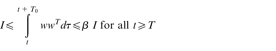
If the regressor vector
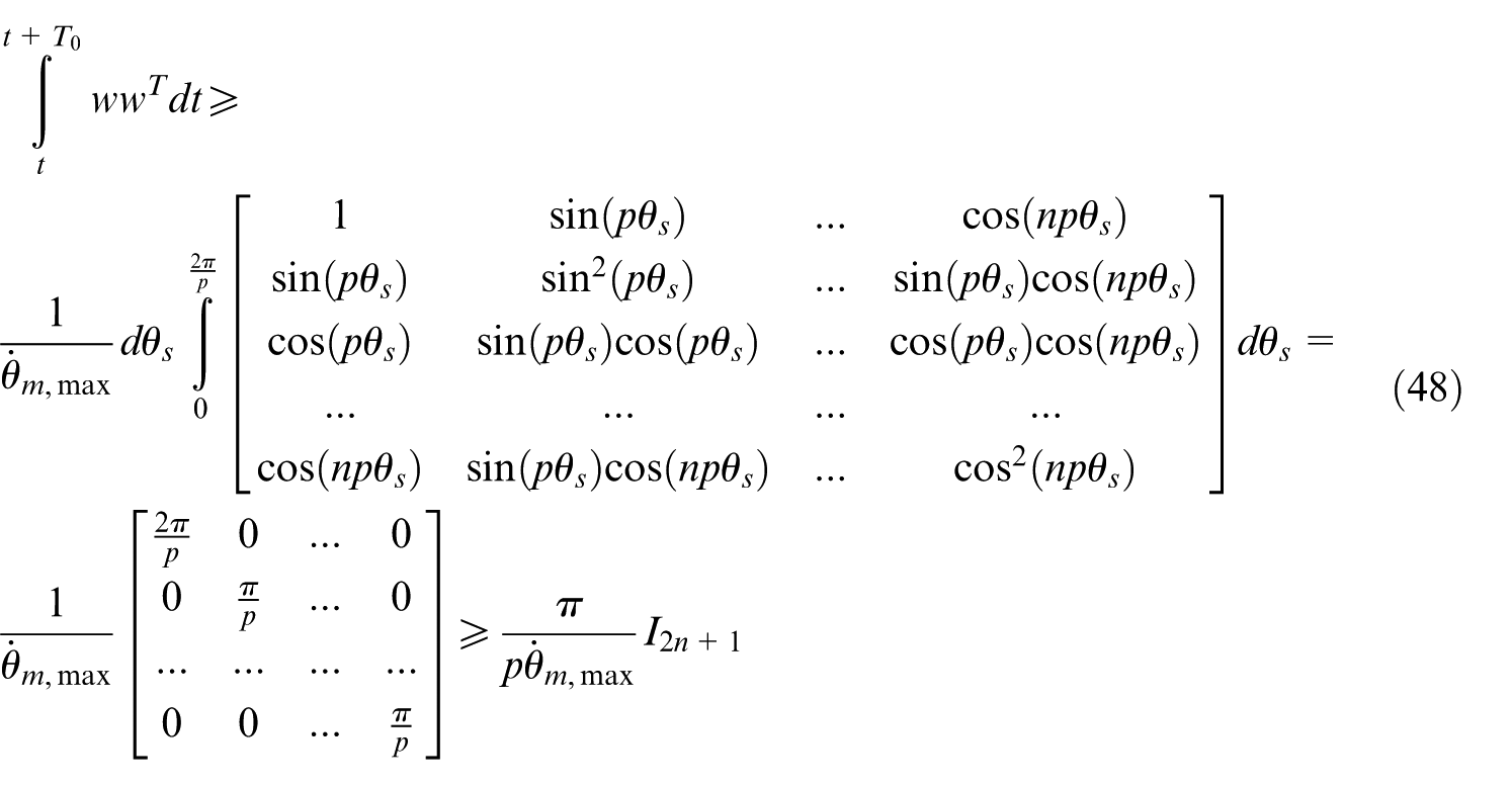
By using these formulations presented above, the conditions on exogenous signals, which ensure persistency of excitation, are specified.
In addition
where
For that reason,
Therefore,
Exponential stability
There exists
Let
Considering

where
For
and
Theorem
Consider the adaptive control system

where
If
This theorem given above can be proved if
Robustness in slow adaptation and stability of the model
With the help of the small-gain theorem, 95 the robustness of the system is provided. While the unperturbed adaptive system is defined as open-loop forward system, the perturbation corresponds to the feedback block. The perturbed system keeps to maintain its stability when the multiplication of the I-O gain of the forward system and that of the perturbation block is less than one. The gain of the forward system is inversely proportional to the adaptation gain in slow adaptation.
Therefore, the robust stability of the system must be considered in slow adaptation process and should not be affected from the adaptation gain. By using coupled Lyapunov function dynamics, 96 the robust stability of the system can be proved.
Theorem
Consider the following adaptive system with linear error equation, nonlinear regressor
where
where
Under these conditions, there exists

and
The perturbed system keeps its stability until the perturbation is sufficiently big with respect to the stability of the matrix
The following conclusions can be obtained by implementing this theorem to our system.
Considering equations (26) and (29), if
Finally, the stability of the adaptive controller with conditions on exogenous signals is derived as follows.
Theorem
For the model described in equations (26) and (29), there exist
Parameter and tracking error convergence can be obtained choosing
Simulation results
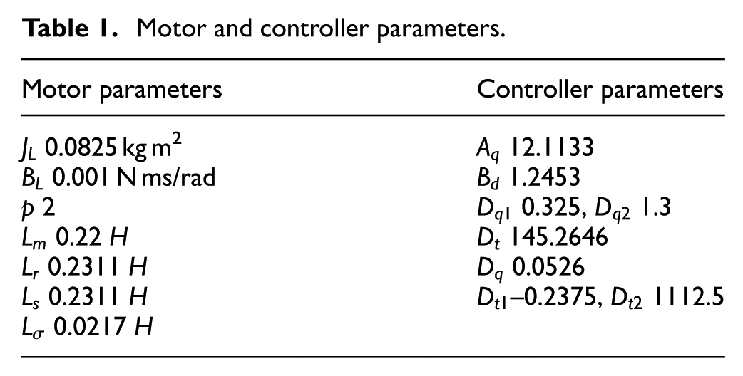
The simulations were conducted in MATLAB/Simulink program using fixed-step ode4 (Rung–Kutta) solver with a Ts = 1e – 5 sampling time. The parameters utilized for IM model and controllers were given in Table 1, respectively. The controller parameters were adjusted by using Simulink Design Optimization toolbox, which was utilized to optimize parameters in Simulink models. The cost function was selected as the sum squared error between the reference speed as experiment data and actual speed. The optimization method is “pattern search-Latin hypercube” with a 0.001 parameter tolerance and 0.001 function tolerance. The parallel pool was used during optimization. The simulations were conducted under the variations of the rotor and stator resistances and motor load torque (see Figures 5–12).
Motor and controller parameters
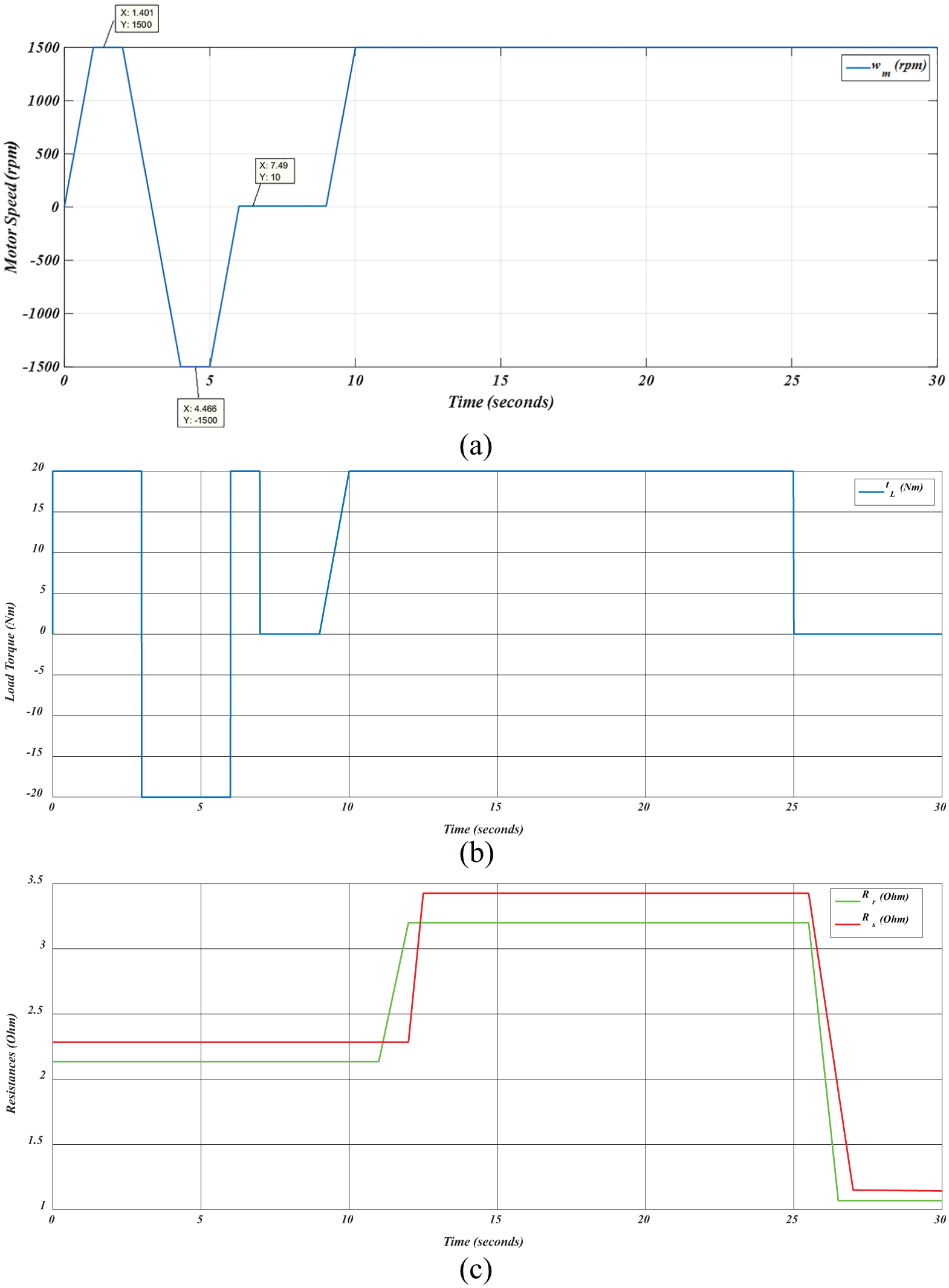
Variations of reference: (a) motor speed, (b) load torque, and (c) stator resistance and rotor resistance.
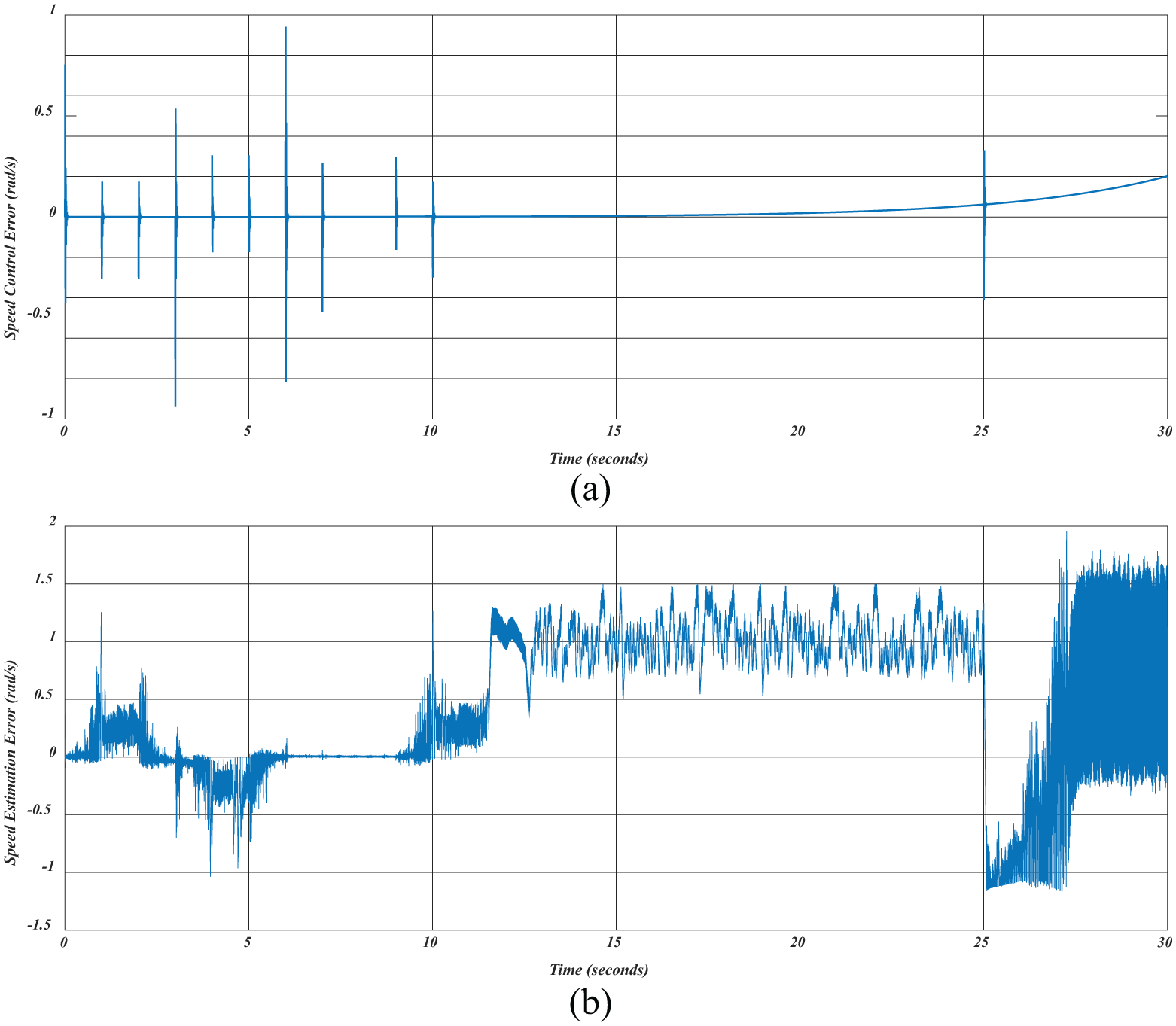
Variations of errors: (a) reference motor speed versus controlled motor speed and (b) controlled motor speed versus estimated motor speed.
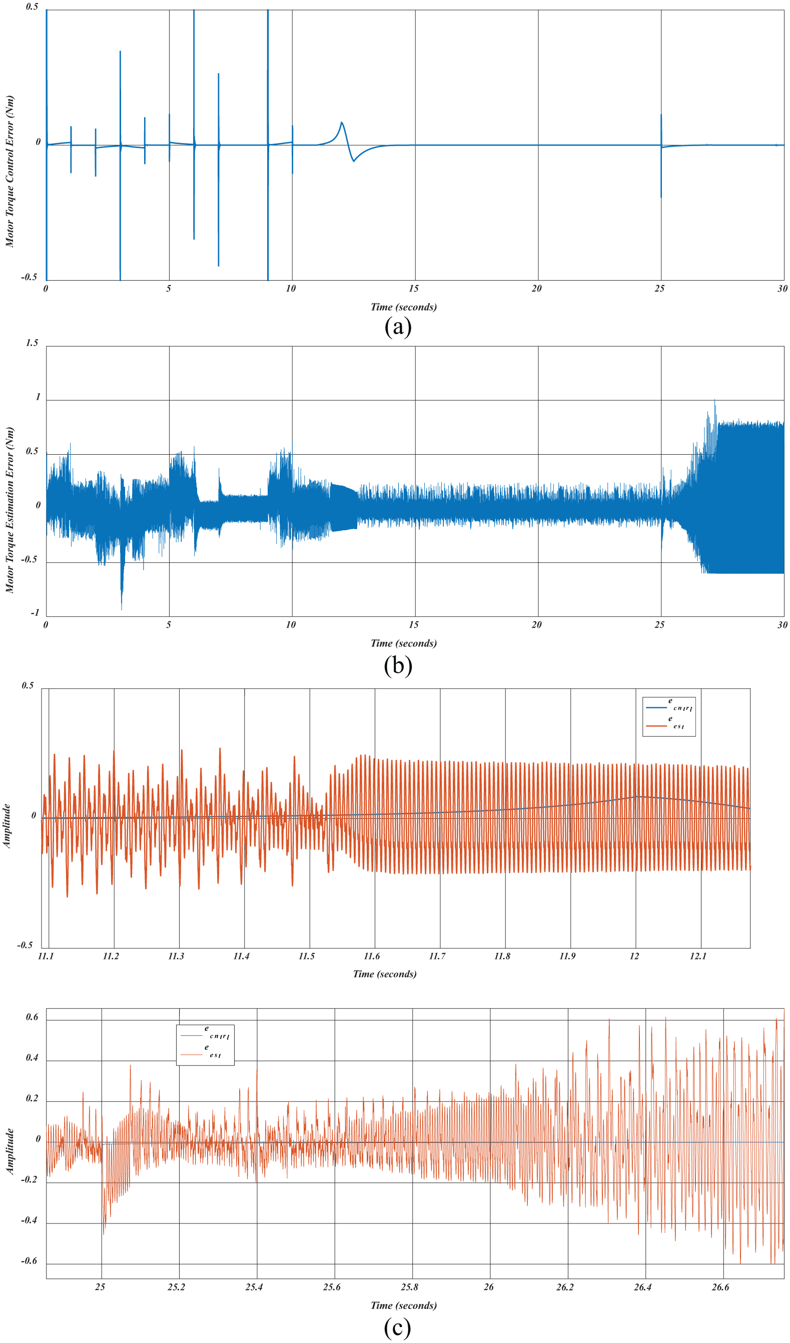
Variations of errors: (a) reference motor torque versus controlled motor torque, (b) controlled motor torque versus estimated motor torque, and (c) detailed view.
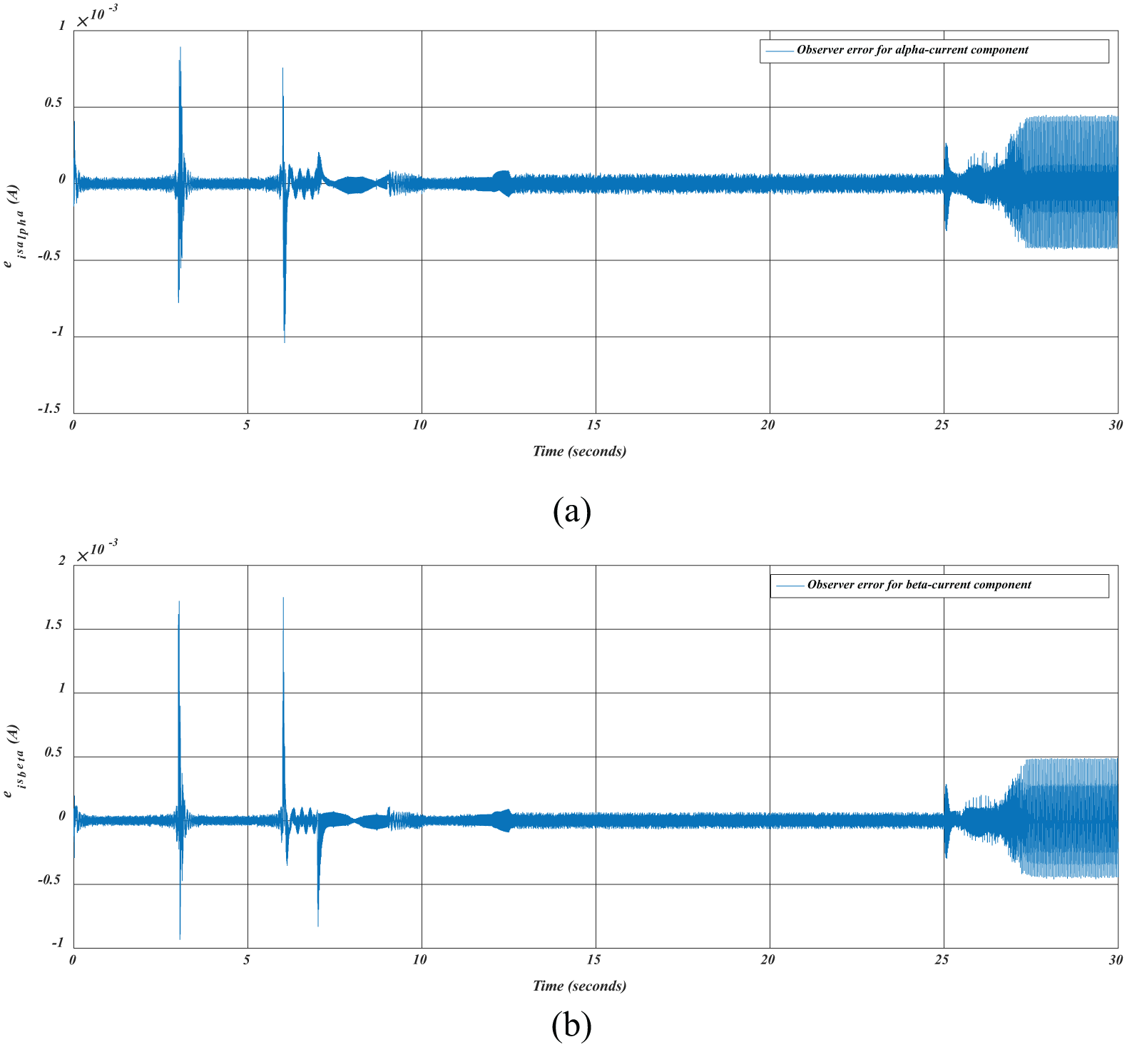
Variations of observer errors for (a) α and (b) β current component.
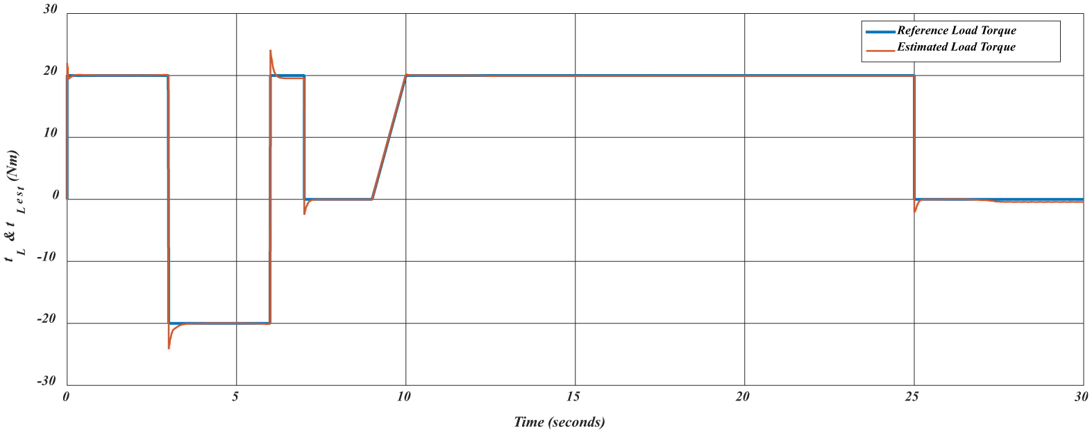
Variation errors of reference versus estimated load torques.
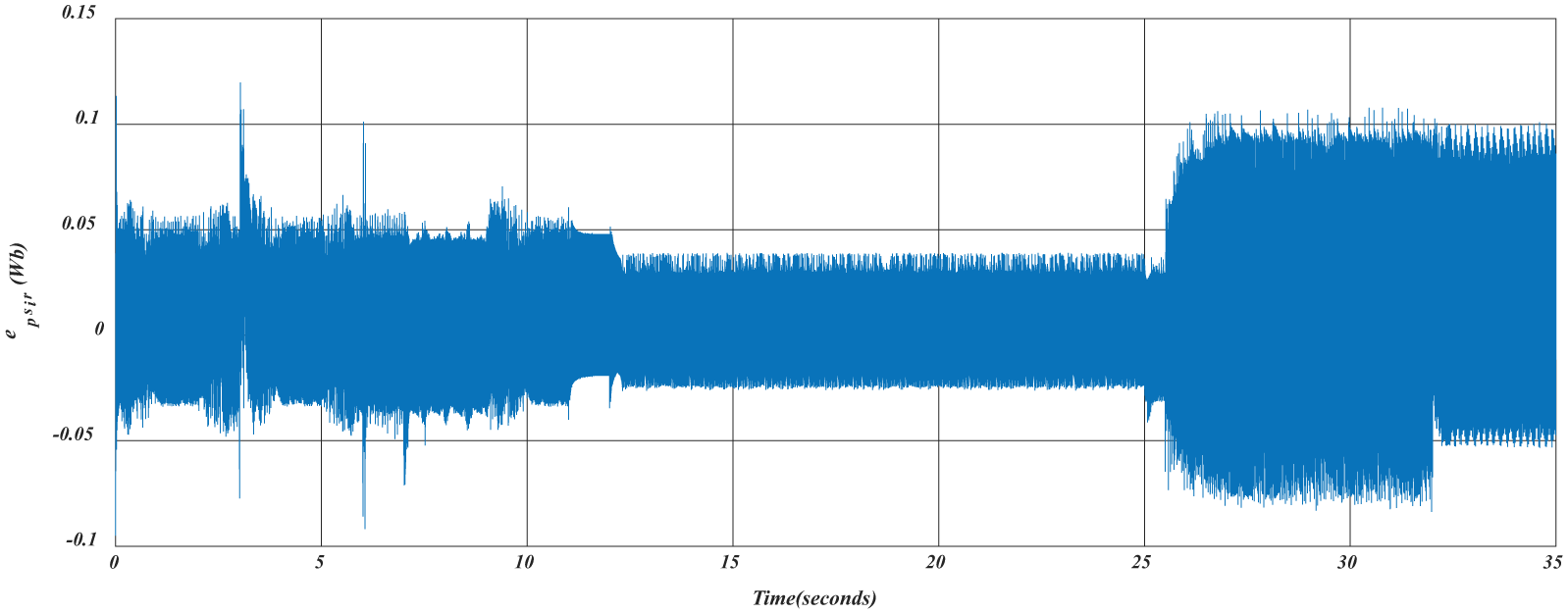
Variation of the error of the rotor flux.
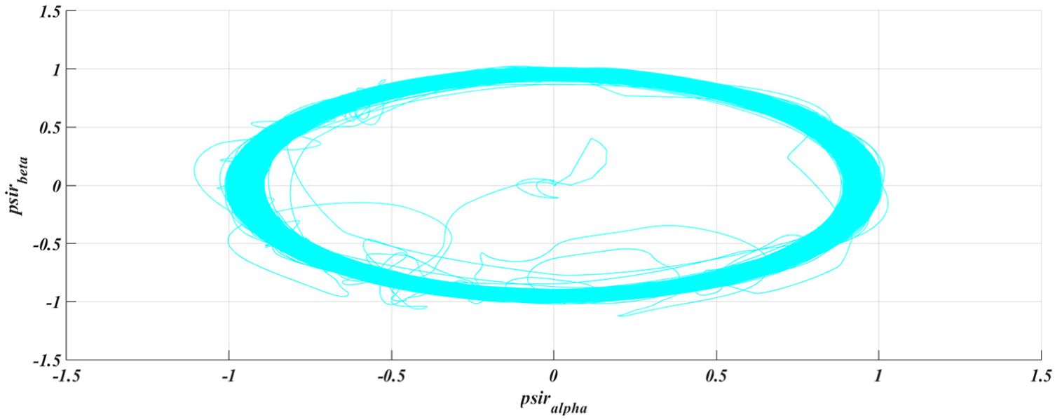
Variation of the stator flux vector.
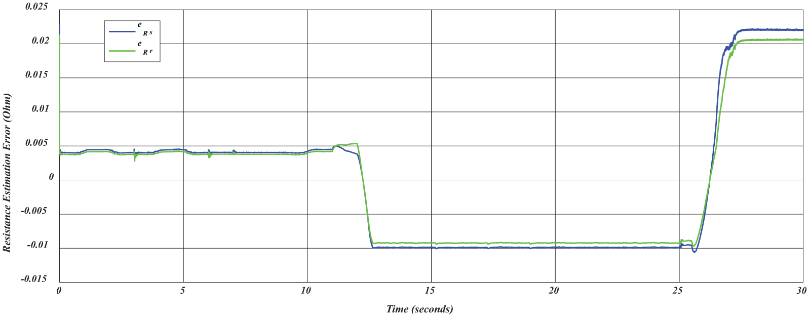
Variations of the estimated and reference: (a) stator and (b) rotor resistances.
To demonstrate the multiple EKF performance, challenging variations are given for the speed reference, load, and stator/rotor resistances. In spite of doubled
Conclusion
IMs are widely used in the industry, thanks to their simplicity and high-power supplement, yet are generally not preferred for industrial robotics and high-power motion control applications due to the difficulties of the sensorless operation occurred at low-speed regions. However, it is possible to utilize the advantages of the IM without sensor in the design of high-power servo systems. The outcomes of this paper will also advance the use of low-cost, low-maintenance, high-power IMs for high-performance applications in extreme conditions, against their high-cost counterparts Permanent Magnet Synchronous Motor (PMSM), Permanent Magnet Direct Current (PMDC), which might be challenged in extreme environments due to demagnetization effects. The major contribution is a more generalized approach to address the above-mentioned challenges of IM’s sensorless position control. To this purpose, novel solutions to the DVC (direct vector control) and DTC of IMs, which involve the following, are proposed:
Robust-adaptive linearizing schemes based on HOSMC with discontinuous and continuous control inputs, in IM control, to achieve increased robustness and accuracy.
Model-based observer implementation approach for the estimation of multiple parameters and states required by the developed control schemes. The approach aims to enhance the performance of the linearizing and decoupling control schemes in general as well as estimation performance at very low and zero speed.
Adaptive torque ripple identification and minimization, with the consideration of the motor torque, thereby taking into account not only the current harmonics but also the space harmonics of the motor.
The proposed control, observer, and torque ripple minimization solutions will address not only problems having connection with position and speed control of IMs but also those related to high-performance motion control, IM-based Hardware in the Loop (HIL) robot control, and other mechatronics applications, such as control of traction motors in hybrid electric vehicles as well as problems related to robust and nonlinear control theory.
In future work, the proposed control schemes take into consideration a direct-drive configuration for the connection of the IM to the dynamic load. The system consists of an IM motor coupled directly to a torque-controlled DC motor on which various dynamic load effects will be generated. The performance of the proposed control and observer schemes will be tested through a hardware-in-the-loop simulator (HILS) test-bed developed for IM-based motion control.
Footnotes
Declaration of conflicting interests
The author(s) declared no potential conflicts of interest with respect to the research, authorship, and/or publication of this article.
Funding
The author(s) received no financial support for the research, authorship, and/or publication of this article.