
Abstract
This article presents a reliable and efficient photovoltaic sliding mode voltage-controlled maximum power point tracking DC-DC converter–active power filter integration system to supply real power to grid. This integrated active power filter system performs power quality enhancement features to compensate current harmonics to make distortion-free grid supply current and reactive power employing nonlinear loads. The proposed proportional–integral–derivative–based sliding mode controller is designed with fixed-frequency pulse-width modulation based on equivalent control approach. The main objective of this paper is to design a photovoltaic system with a new sliding surface to force the photovoltaic voltage to follow the reference maximum power point voltage with the alleviation of slow transient response and disadvantages of chattering effects of variable-frequency hysteresis modulation sliding mode controller–maximum power point tracking. The perturbations caused by the uncertainties in climatic conditions and converter output bulk oscillations during grid integration are also mitigated. The features of the proposed photovoltaic–active power filter integration system are confirmed at different operating conditions through PSIM simulation software, and its performance is also compared with a conventional variable-frequency sliding mode-controlled maximum power point tracking. The obtained simulation and experimental results give good dynamic response under various operating conditions of environmental and local load conditions.
Keywords
Introduction
Nowadays, the integration of renewable energy sources at distribution level called distribution generation (DG) is becoming a challenging technology due to global warming, green house gas emission and environmental contamination.1–3 Recently, among the various types of DG system, two-stage grid-integrated photovoltaic (PV) system especially microinverter (PV module-integrated converter) becomes more popular because of its own maximum power point tracking (MPPT) capabilities, cost reduction in end-users, simplified system installation and fulfilment of voltage gain requirement.4–6 However, in two-stage PV system, the dynamic interaction among the DC-DC converter, inverter and MPPT controller may decrease the system performances in terms of system efficiency and confused in voltage-oriented MPPT techniques, for example, perturb and observe (P&O) method. This is mainly due to PV voltage oscillations caused by the second harmonic frequency of the grid 7 and nonlinear characteristics of PV cells depending on irradiance and temperature. 8 Among the various solution methods proposed in grid-integrated PV system to mitigate such voltage oscillations, the most preferable and the first alternative is a linear proportional–integral (PI) + pulse-width modulation (PWM), proportional–integral–derivative (PID) + PWM or peak current mode + PWM controller. These controllers ensure stability with the ability to track the PV voltage reference generated by the MPPT algorithm under uncertainties in load perturbations and climatic conditions.7,9,10 However, the main problem associated with these controllers is loss of stability due to low-frequency sinusoidal voltage perturbations imposed by the grid in the DC bus. Thus, the necessity of linearizing the model of PV system arises to ensure same performances in all the operation ranges.2,3,11 Focusing the nonlinear controllers, particularly sliding mode controllers (SMCs), is a better candidate than conventional linear controllers for mitigating such low-frequency oscillations and load perturbations due to their excellent characteristics of stability, simpler implementation and robustness against parameters which are common in PV system.4,12,13 However, SMC approach applied to MPPT DC-DC converter has certain limitations in the design of filter circuit due to variable operating frequency and high chattering magnitude such as PV voltage fluctuations. Hence, to ensure stability of a voltage-oriented MPPT algorithm with fast settling time, alleviating high chattering magnitude and mitigating low-frequency oscillations of the PV voltage especially in grid-connected environment, the necessity of constant frequency operation of SMC-MPPT converter is an important one in this concern.14–16
This paper proposes a design procedure of PID-based sliding mode (SM) voltage controller for PV-MPPT application. The discussion of SM control theory based on variable-frequency hysteresis modulation and equivalent control approach based on fixed-frequency PWM duty ratio concept is focused in this paper. The dynamic state-space modelling method for designing SM voltage-controlled MPPT high step-up DC-DC converter in terms of the desired control variable (i.e. voltage) is outlined in this regard. The introduction of voltage error integral term in the control computation is to reduce the steady-state PV voltage error of the SM-controlled system.
With prevalent increase in power electronic equipments and use of nonlinear loads at the point of common coupling (PCC), current and voltage distortion is produced in distribution grid which affects the quality of power. 2 To maintain good quality of power at PCC, various national and international agencies have released standards and guidelines that specify limits on the magnitudes of harmonic distortion in currents and voltages. 17 In order to provide harmonic-free grid supply current, the solution is the use of active power filter (APF) technology having better compensation characteristics to inject harmonic current with suitable magnitude and phase into the PCC. In most of the literatures, control strategy of inverter in grid-connected mode concentrates only on injecting active power to the grid and not on power quality functions employing nonlinear loads such as compensating harmonics and reactive power drained by local loads, particularly APF integration functionality.3,10
The main contribution of this paper is to provide the effective integration of PV energy source into the distribution grid with power quality features that can be done by constant-frequency SMC-MPPT high step-up DC-DC converter6,5,18,19 connected with grid-interfacing inverter. With the aid of MPPT converter, the possibility of faster response in P&O MPPT control variable has superior tracking performances of PV in the poor atmospheric conditions. The grid-interfacing inverter has additional features of shunt active power filtering capability without additional cost of implementation and performs good power quality features at PCC feeding a various linear and nonlinear loads.8,11 SMC-MPPT DC-DC converter connected with grid-interfacing inverter will act as microinverter with active filtering capability to compensate the low-frequency voltage ripple on the DC-side of the PV system.20,21
The entire features can be done by either separately or simultaneously with suitable control of inverter. A simple and cost-effective nonlinear control scheme is applied to the control of single-phase grid inverter. 22 The inner current controller used is based on SMC to force the current of the inverter to track their reference value. The suggested SM control of inverter and MPPT converter has been found to be practicable, cost-effective and excellent compensation characteristics especially in low- and medium-scaled PV systems.
The proposed PV-APF integration system is simulated in PSIM environment for different operating conditions of loads and uncertainties in climatic condition. The transient and steady-state performances of proposed fixed-frequency PWM-based SMC-MPPT configuration can be compared with variable-frequency hysteresis modulation-based SMC-MPPT configuration.
Description of system configuration
The configuration of the proposed double-stage PV-APF combination system using variable- and fixed-frequency SMC-MPPT converter is shown in Figures 1 and 2, respectively. The PV module is connected to the DC-DC converter in which boost, flyback and forward operation are integrated on a single magnetic core to achieve high step-up voltage with low duty ratio. The operation of high step-up DC-DC converter is based on command signal derived from SM controller with voltage-oriented P&O MPPT technique implemented to extract maximum PV power. The main objective of the proposed SM controller is to provide good dynamic response of PV system under variation of environmental, load uncertainties, sinusoidal oscillations imposed by the grid and to ensure the accurate tracking of reference PV voltage provided by the MPPT algorithm.7,8 The nonlinear load which is constructed using full-bridge diode rectifier with a smoothing inductor and DC filter capacitor connected to the grid is considered as a step change in load. The single-phase H-bridge inverter is connected between the MPPT converter and the distribution grid. The integration of APF functionality in grid inverter needs a particular attention for the generation of reference current and design of controller. The nonlinear controller based on SMC law is used to implement the voltage and current controller of the inverter.
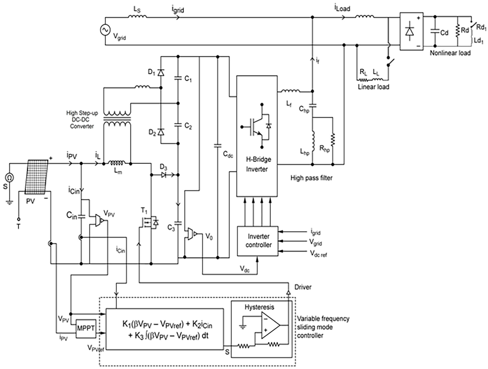
Configuration of PV-APF combination system employing variable-frequency hysteresis modulation-based SMC-MPPT converter.
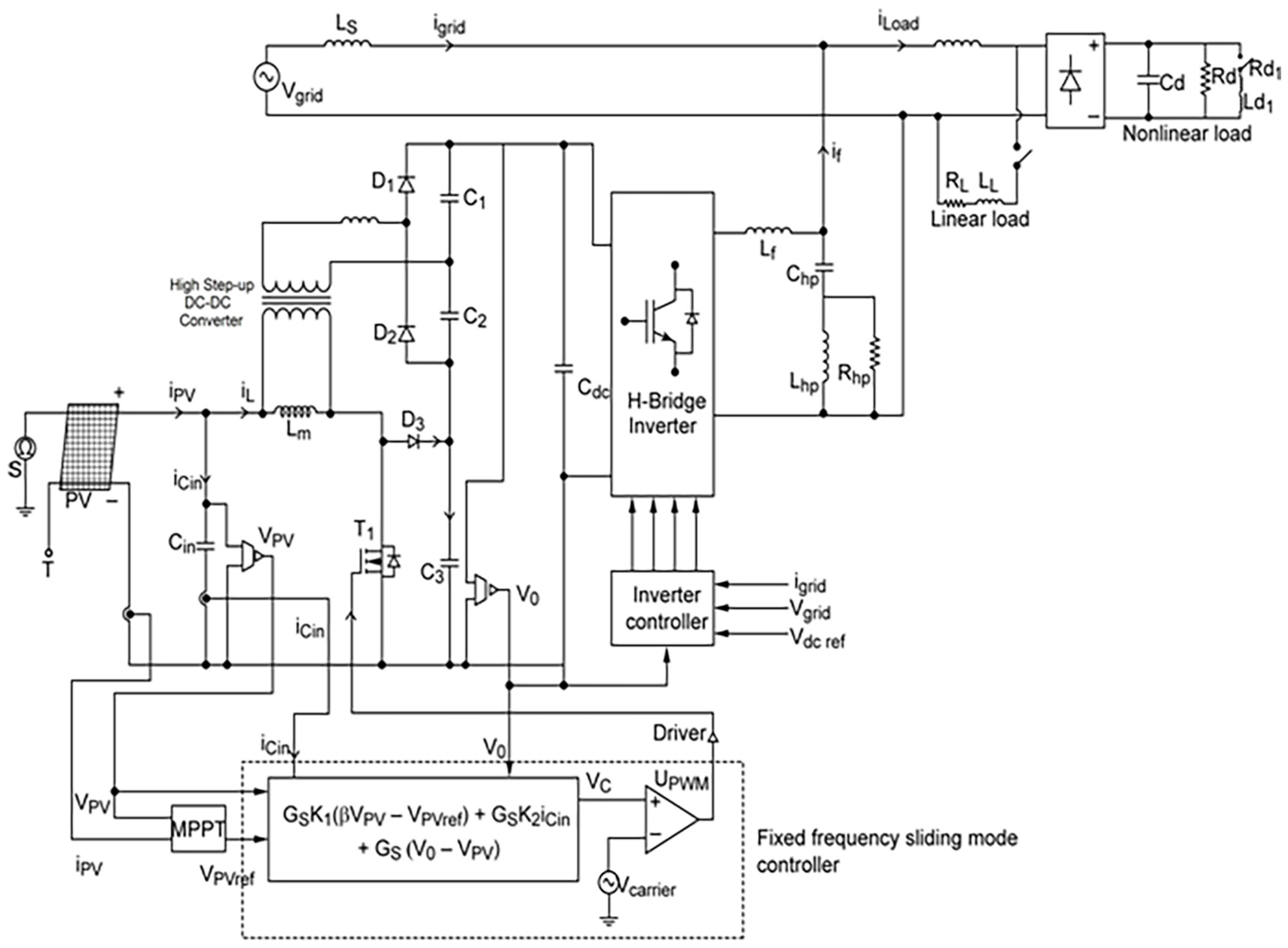
Configuration of PV-APF combination system employing fixed-frequency PWM-based SMC-MPPT converter.
The functions that can be carried out by the inverter controller are as follows:
The control of active power flow from PV source to PCC;
Compensation of reactive power demanded by the load and the nonlinear load current harmonics, keeping the distortion-free sinusoidal grid supply current.
In the daytime with availability of PV energy, the PV-APF combination system brings all its functions into operation. During nighttime and no sunlight periods, the power required by the local loads is consumed from the grid source while the inverter system performs shunt active power filtering function to compensate harmonic currents and reactive power. Thus, the utilization level of the PV-APF combination is higher than the conventional grid interactive PV inverter system.
Gain of the high step-up DC-DC converter
From steady-state operating modes of DC-DC converter (see Figures 1 and 2), the voltage developed across the capacitor C3 is derived as equal to the output voltage of conventional boost converter 18
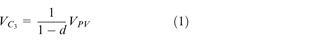
where d is the duty cycle of converter.
Due to flyback operation of coupled inductor, the voltage developed across the output capacitor C1 is derived as
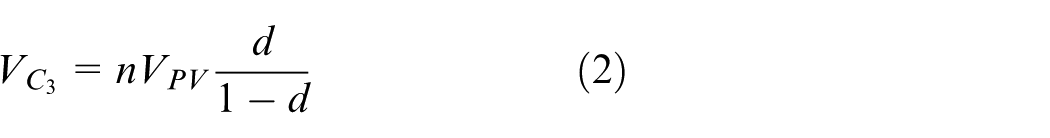
Due to forward operation of coupled inductor, the voltage developed across the output capacitor C2 is derived as

Thus, due to the series connection nature of C1 and C2, the resultant output voltage is a function of boost converter with multiplication factor of ‘n’

This voltage is added with the boost converter output voltage and resultant output voltage can be derived as
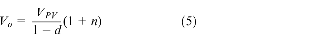
Variable-frequency hysteresis modulation-based SM-controlled MPPT converter
The general SM control law of DC-DC converter employing single switch to adopt a switching function is given as
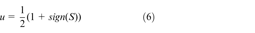
where
The usual method of implementing the SM controller based on the control law described in Equation (6) is realized easily by switch relay and through an analogue or digital computational circuit. However, the direct implementation of this control methodology results in unpredictable frequencies which are not suitable for the control purpose of the converters.
One of the most popular techniques of operating frequency in a controllable way is hysteresis modulation. This method does not concern about additional computational circuitries, and its implementation can be done simply by defining the logic state of power switch T1 as
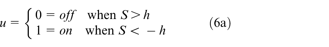
and the sliding surface S is

where
The controlled state variables are expressed as
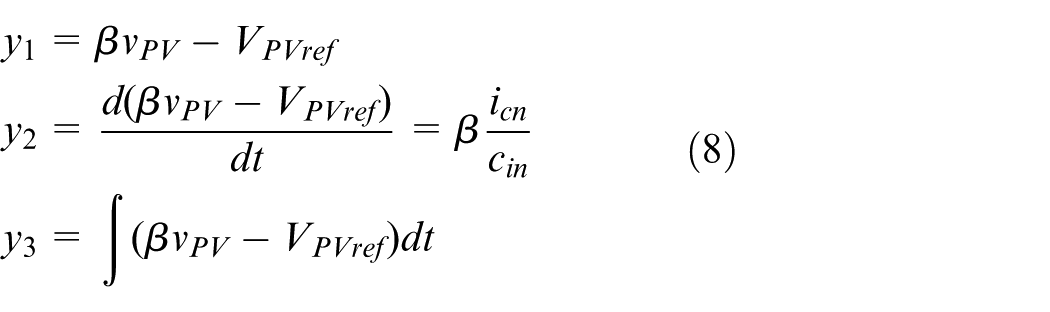
where
Using Equations (7) and (8)
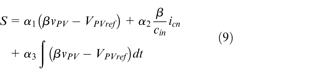
Equation (9) directly relates
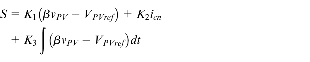
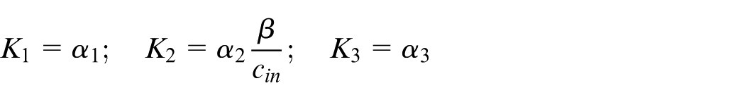
where the gain parameters are
The realization of variable-frequency hysteresis SM operation can easily be achieved by implementing control Equation (9) into a controller (see Figure 1). The gating signal is generated using Schmitt trigger–type hysteresis comparator. In general, due to the presence of hysteresis band in switching function, an error will be introduced in the PV voltage. So, it is essential to select the hysteresis band
Fixed-frequency PWM-based SM-controlled MPPT converter
The discrete gate signal
The time differentiation of Equation (7) to zero gives the equivalent control signal of the proposed fixed-frequency SM controller as
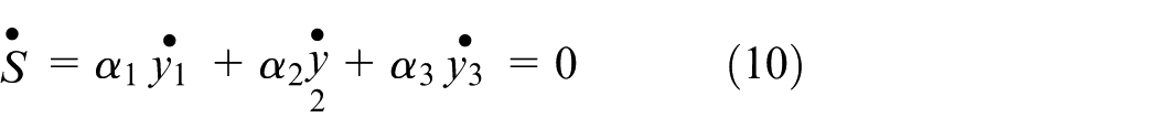
The time differentiation of Equation (8) gives the dynamic model of the proposed system derived as
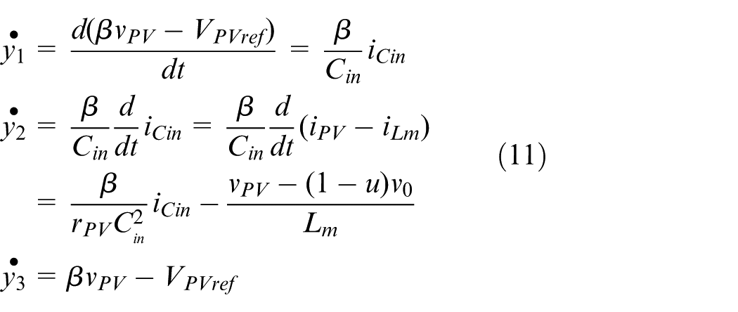
where
The control signal of the proposed SMC based on equivalent control approach is derived by solving Equation (10) and inequality
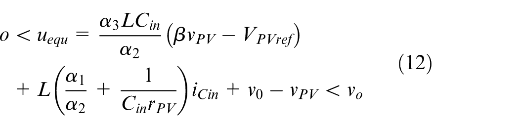
The control signal
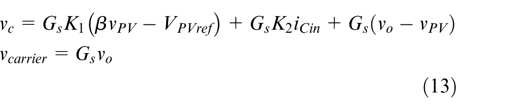
where the gain parameters of the proposed controller are as follows
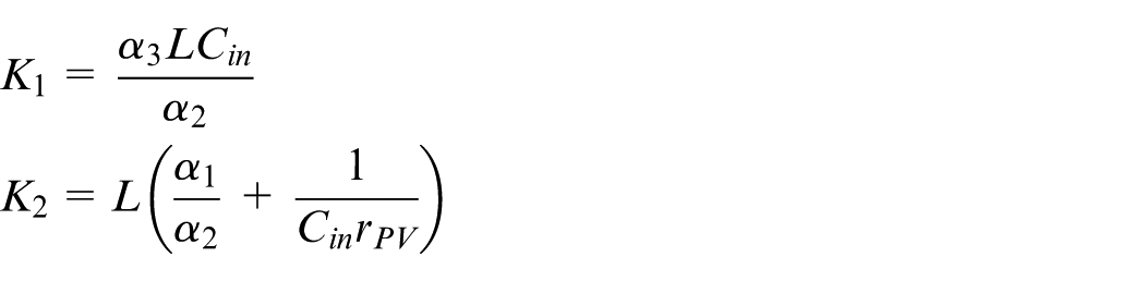
A suitable scaling factor
Selection of sliding coefficients
The choices of sliding coefficients based on the desired dynamic properties are made using Ackermann’s formula. 16 Hence, the equation governing the sliding coefficients for the transient response of the converter during SMC-MPPT operation can be easily determined by substituting S = 0 in Equation (7) which results in a linear second-order equation
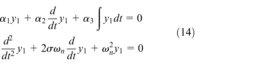
where
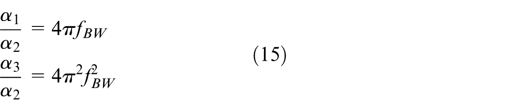
Thus, the design of the sliding coefficients depends on the bandwidth
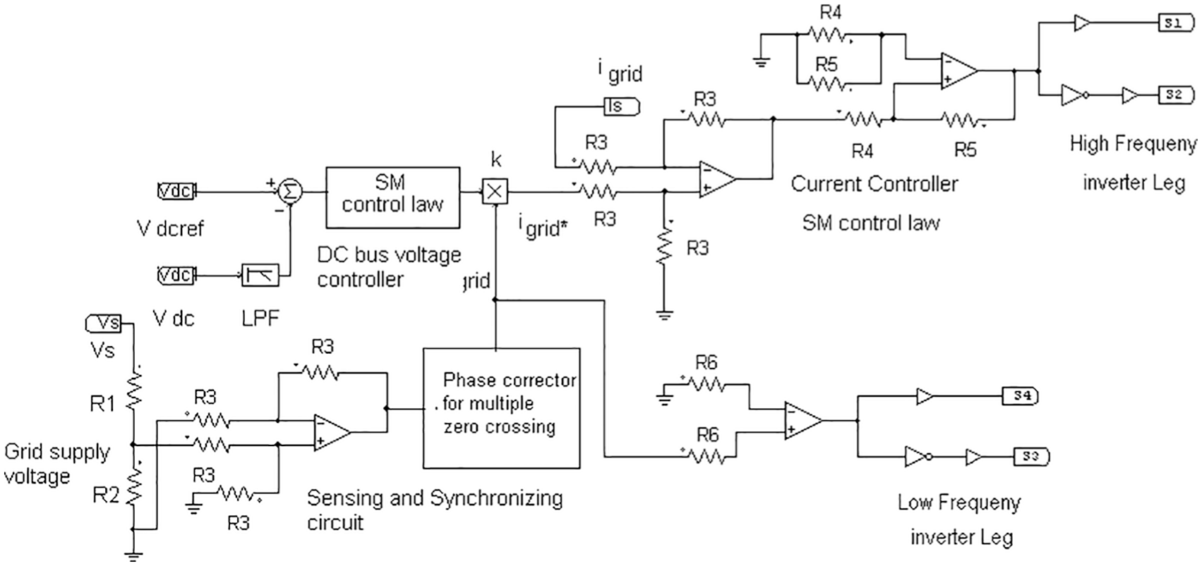
Inverter control strategy and model
The control scheme of the grid-interfacing inverter is shown in Figure 3. It consists of inner-loop current controller, outer-loop voltage controller and modulation scheme. The principle scheme of inner-loop current controller is by forcing the grid supply current

where
Inverter control scheme.
A standard form of simple sliding surface,

Practically, the voltage at the PCC is distorted due to the presence of source impedance and nonlinear current flowing through it. Such supply systems are represented as weak or non-stiff sources. When compensation is applied to non-stiff sources, the PCC voltage may have multiple zero crossings due to the switching harmonics in the grid supply current and at such circumstances, it is difficult to extract zero crossing instance of the PCC voltage. So, it is important to detect the zero crossing instants of the voltage to attain reliable operation of the grid inverter functioning as an APF. Conventionally, a phase-locked loop (PLL) is used to create unity sinusoidal voltage in synchronization with grid inverter.23–25 However, due to inherent delay in the PLL, the transient response of the grid inverter is affected. Newly developed single-phase PLL structures and its high-performance features are reported in several publications.26–29 However, such schemes cannot be easily implemented due to the complexity in different way of presentations and lack of comprehensive knowledge about their dynamic features and stability.
In this work, the simple and low-cost grid synchronization circuit is designed particularly for a low-scaled, two-stage grid-integrated PV system which is a combination of low-pass filter (LPF) and phase corrector. The sensed and scaled PCC voltage is passed to LPF which is designed for extracting the 50-Hz fundamental frequency component. The phase shift introduced by the LPF is corrected using phase corrector (which consists of an adjustable resistor that can be used to adjust the value of phase shift). The phase corrector output signal is used to synchronize the operation of grid inverter with PCC voltage. With the presented synchronization circuit, proper sequencing of the operation of grid inverter can be attained even under the multiple zero crossings of grid supply voltage.
The nonlinear control law used to implement the current controller of inverter is stated in Table 1. Usually, the SM control law which forces the grid supply current to track the reference current can be expressed as

SMC law for grid inverter.
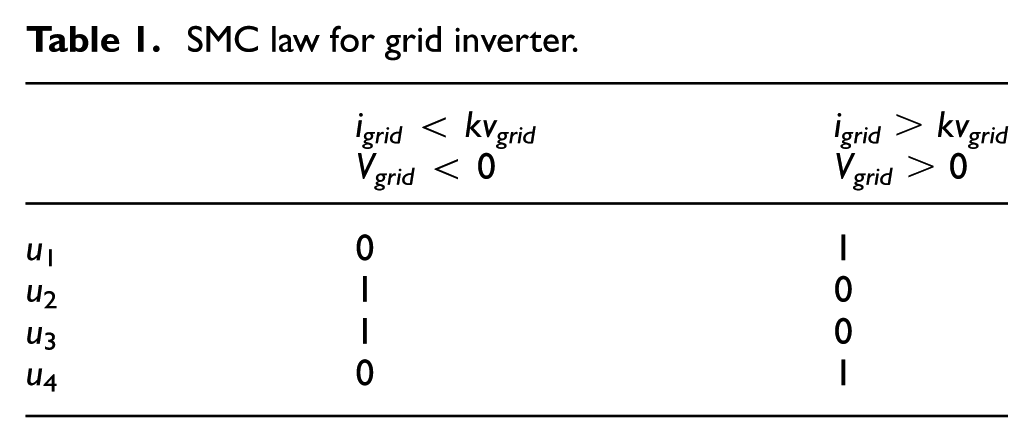
where
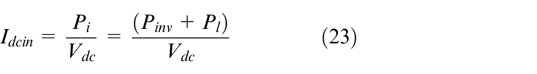
The grid inverter used in APF topology is operated in current-controlled voltage source inverter (CCVSI) which uses DC bus capacitor as the supply and switches at high frequency to generate a necessary compensation current that follows the current reference equal to the reactive load current and harmonic load current. From inverter controller scheme shown in Figure 3, the DC bus capacitor voltage,
Hence, the output of the PI voltage controller,
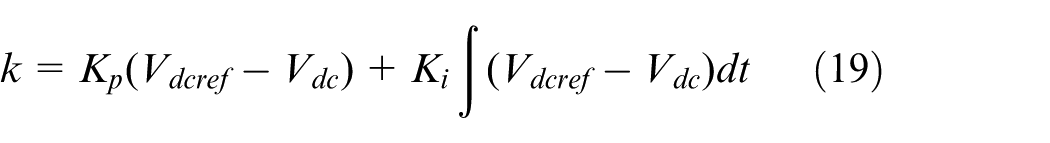
where
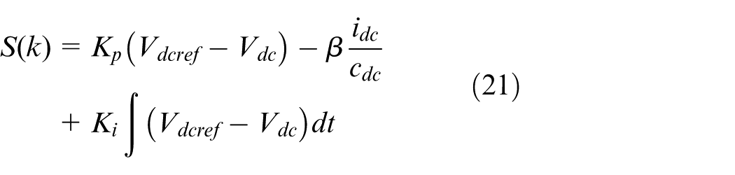
The PI voltage controller is replaced with the PID-SM voltage controller to achieve the fast dynamic response similarly as in Equation (8)
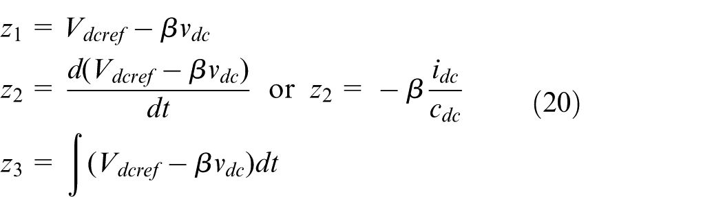
Hence, the derived sliding surface of the voltage controller is
The SMC-MPPT converter collects maximum available power from PV source and feeds into the DC bus of the grid-interfacing inverter. Hence, the DC bus plays a very important role in supplying this unpredictable nature of power from PV source to the grid.
The current,
where
where
The two switches in each leg of H-bridge inverter must operate in complementary manner. This ensures that at any time, one switch will be conducting and simultaneous conduction of two switches is prohibited.
This represents

The average modelling of generated inverter output voltage,

Similarly, the charging current,

The average state-space model of H-bridge inverter can be expressed as
Results and discussion
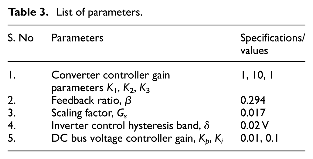
The proposed single-phase, two-stage grid-integrated PV system employing nonlinear loads with APF functionality is simulated and its operation under various conditions of climatic, grid, DC bus voltage and load is investigated. A single-phase grid supply of 110 V, 50 Hz is considered and is connected to the nonlinear load. The proposed simulation study components and design parameters are represented in Tables 2 and 3, respectively.
List of components.
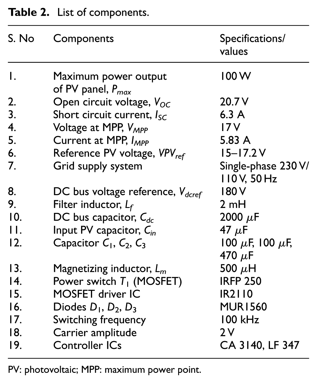
PV: photovoltaic; MPP: maximum power point.
List of parameters.
Pure shunt active power filtering mode
In the absence of PV energy (
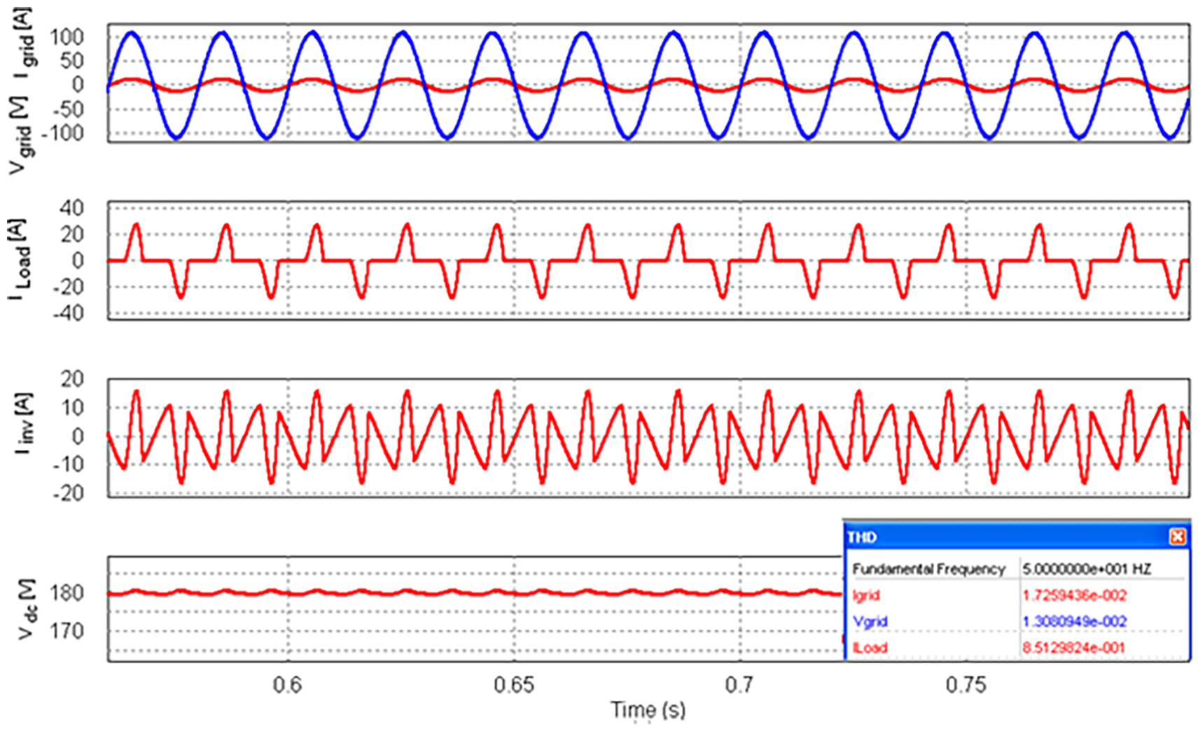
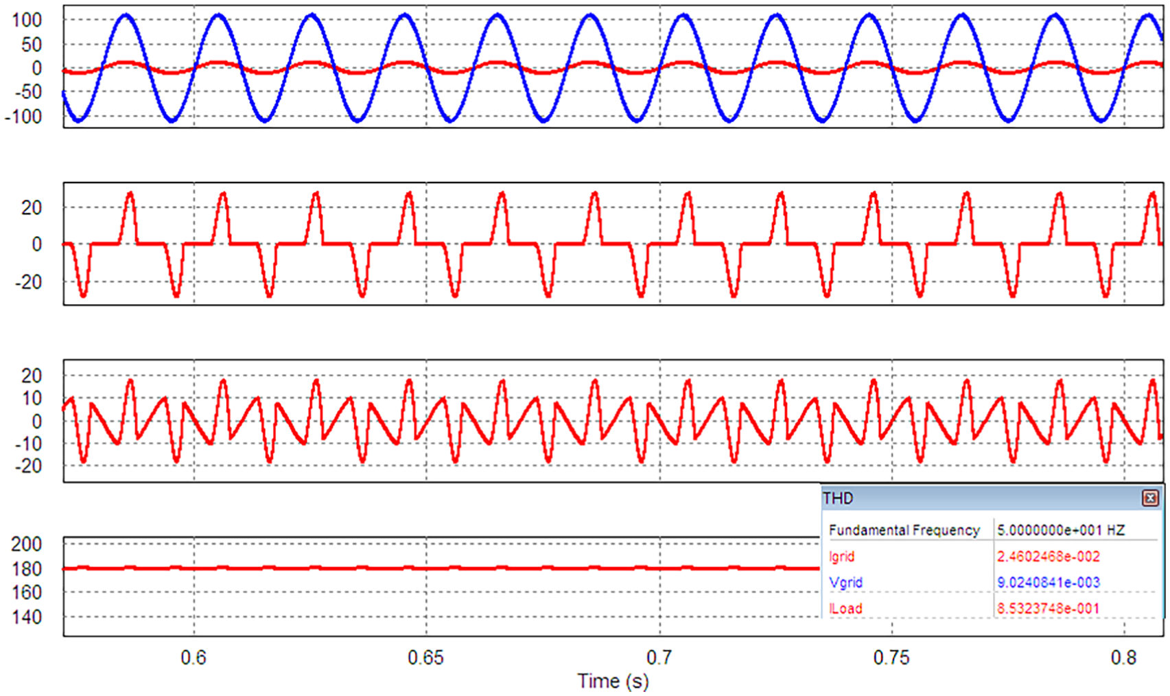
Resultant waveforms of grid source voltage, grid source current, load current and inverter output current during steady state (Rd = 15 Ω and Ld = 3 mH).
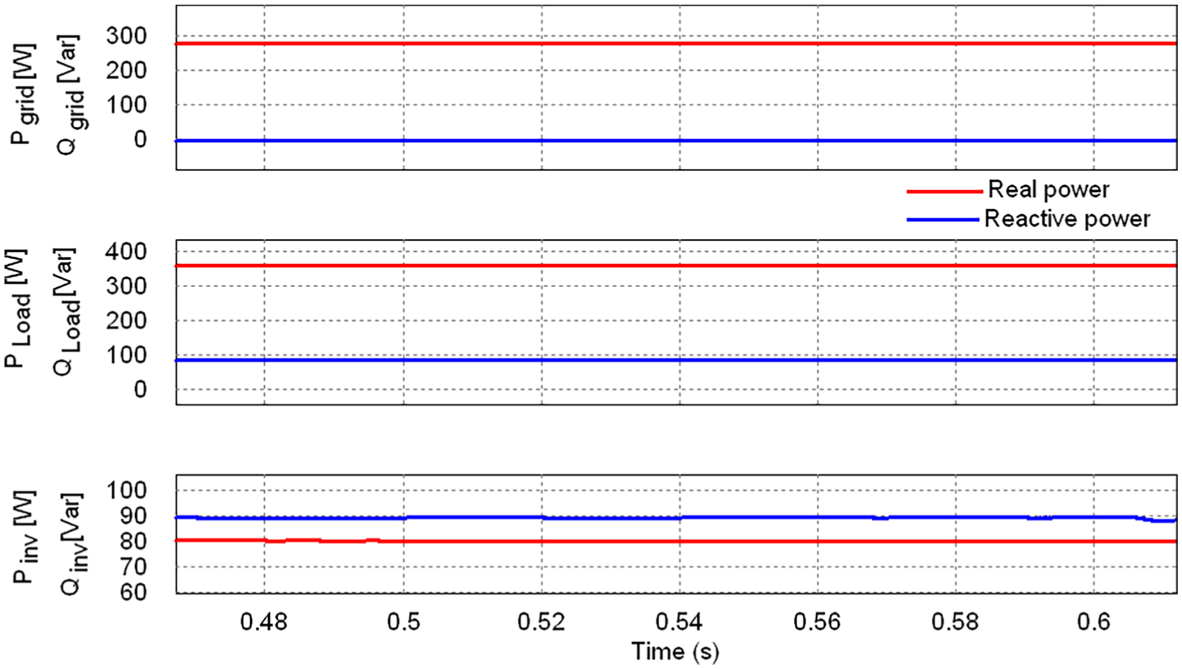
The resultant real and reactive power obtained in grid source side, load side and inverter output side is shown in Figure 5. The real and reactive power profile obtained is illustrated in Table 4. The harmonic profile of the proposed PV-APF combination system is represented in Table 5. The total harmonic distortion (THD) of grid source voltage, grid source current and load current obtained during steady state is 1.31%, 1.72% and 85.12%, respectively. Figure 6 shows the response of the grid source current, source voltage, load current, inverter output current (filter current) and DC bus voltage with step change in nonlinear load condition at t = 2 s. These responses illustrate that irrespective of the nonlinearity of load changes, load type and presence of distortions in load current, the grid supply is close to sinusoidal and free from distortions. The measured THD of the grid supply (voltage and current) is less than 5% which meets the specified limits of the IEEE-519 harmonic standard. At a period t = 2 s, the step change in load occurs from 360 to 720 W and the response of DC bus voltage is lightly perturbed and settled with a maximum time period of 0.2 s.
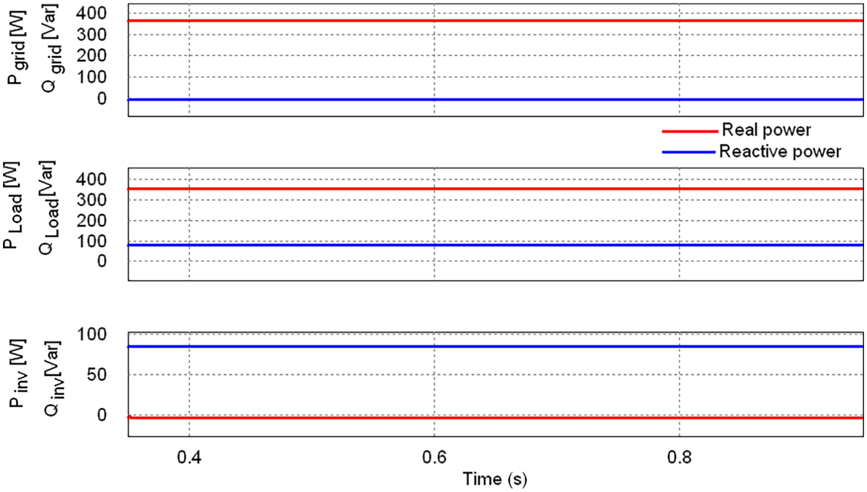
Real and reactive power profile in shunt active power filtering mode
Real and reactive power profile.
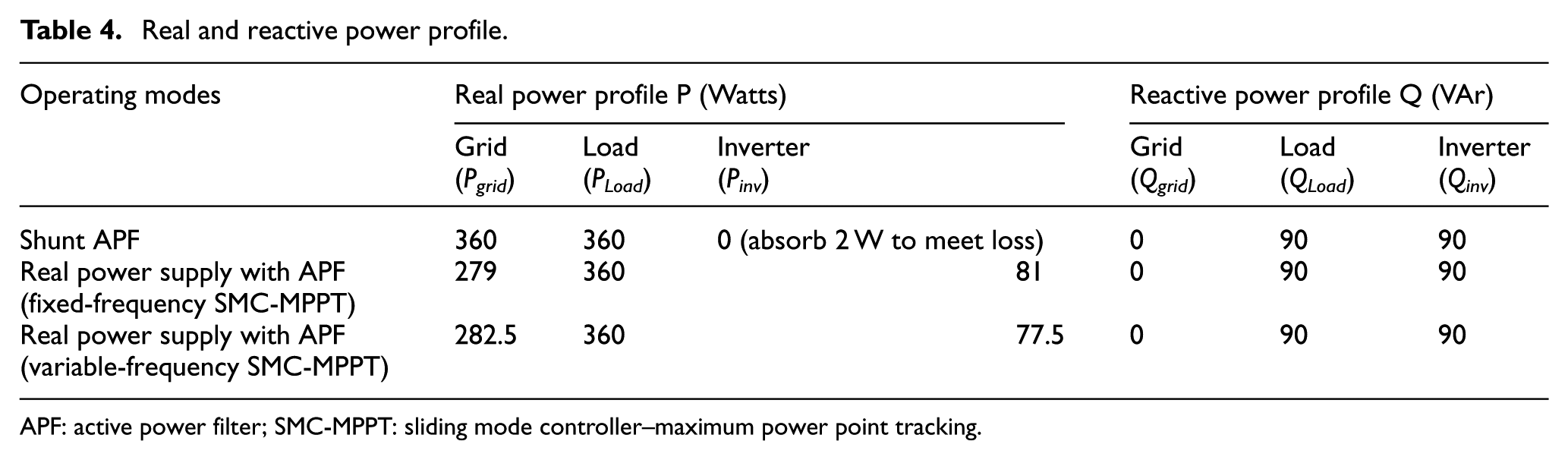
APF: active power filter; SMC-MPPT: sliding mode controller–maximum power point tracking.
Measurement of THD in PV-APF integration system.
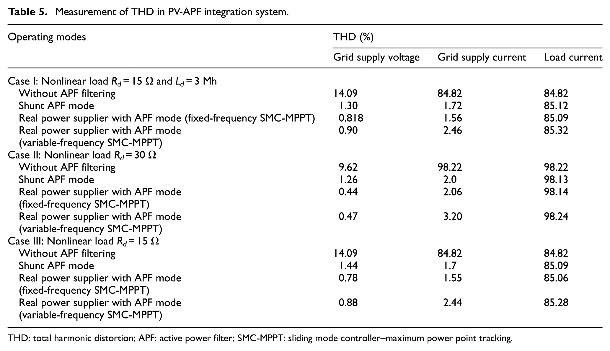
THD: total harmonic distortion; APF: active power filter; SMC-MPPT: sliding mode controller–maximum power point tracking.
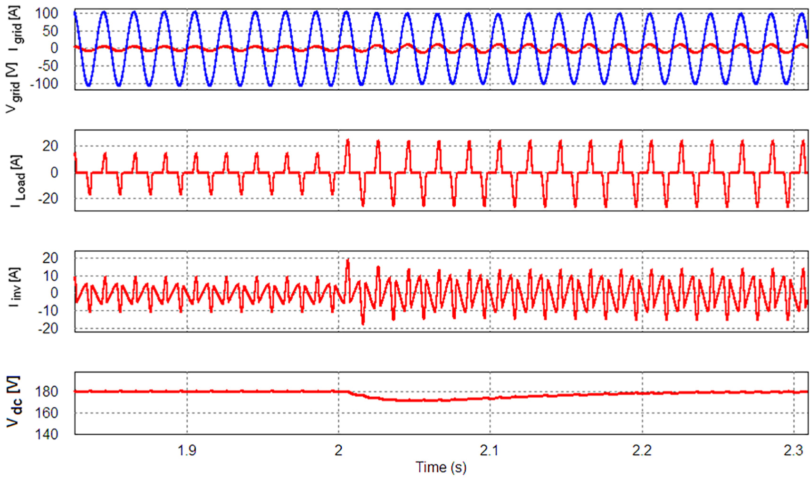
Dynamic response of source current, inverter output current and DC bus voltage with step variation of load (Rd = 30 Ω to Rd = 15 Ω and Ld = 3 mH).
Real power supply with shunt active power filtering mode (PV-APF integration system)
In the presence of PV energy (
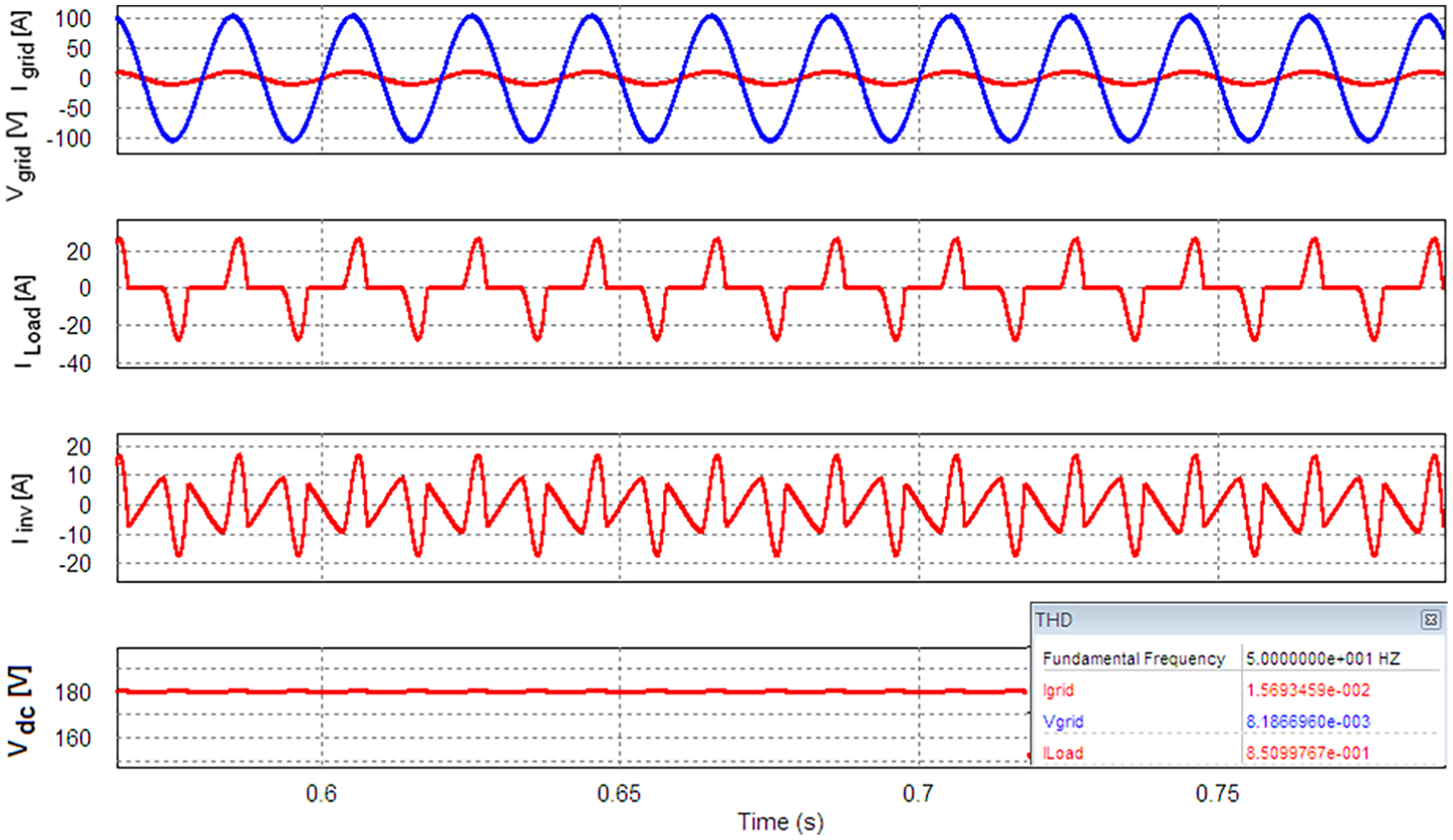
Waveforms of grid source voltage, grid source current, load current, inverter output current and DC bus voltage with fixed-frequency SMC-MPPT operation during steady state (Rd1 = 15 Ω and Ld = 3 mH).
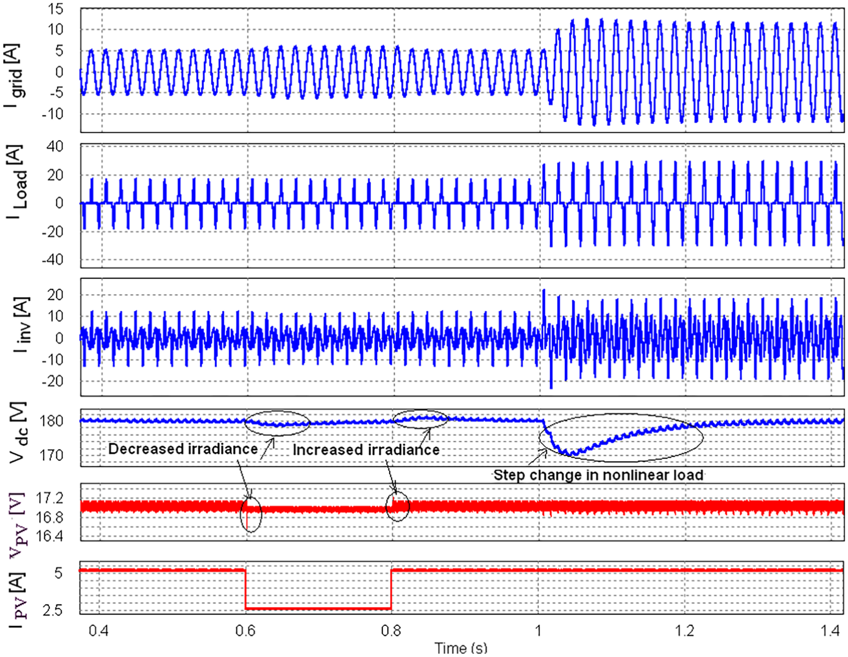
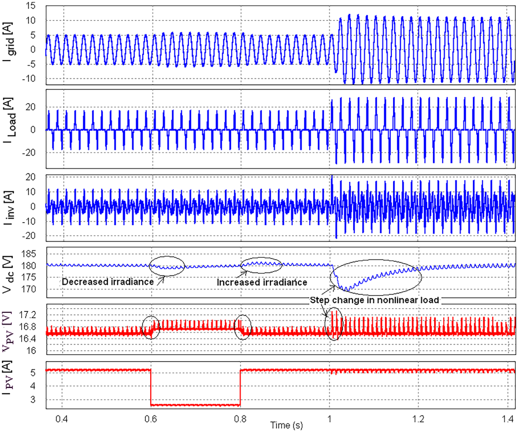
Dynamic response of grid source current, load current, inverter output current, DC bus voltage, PV voltage and PV current with perturbation in irradiance and step variation of nonlinear load (Rd = 30 Ω to Rd1 = 15 Ω and Ld1 = 3 mH).
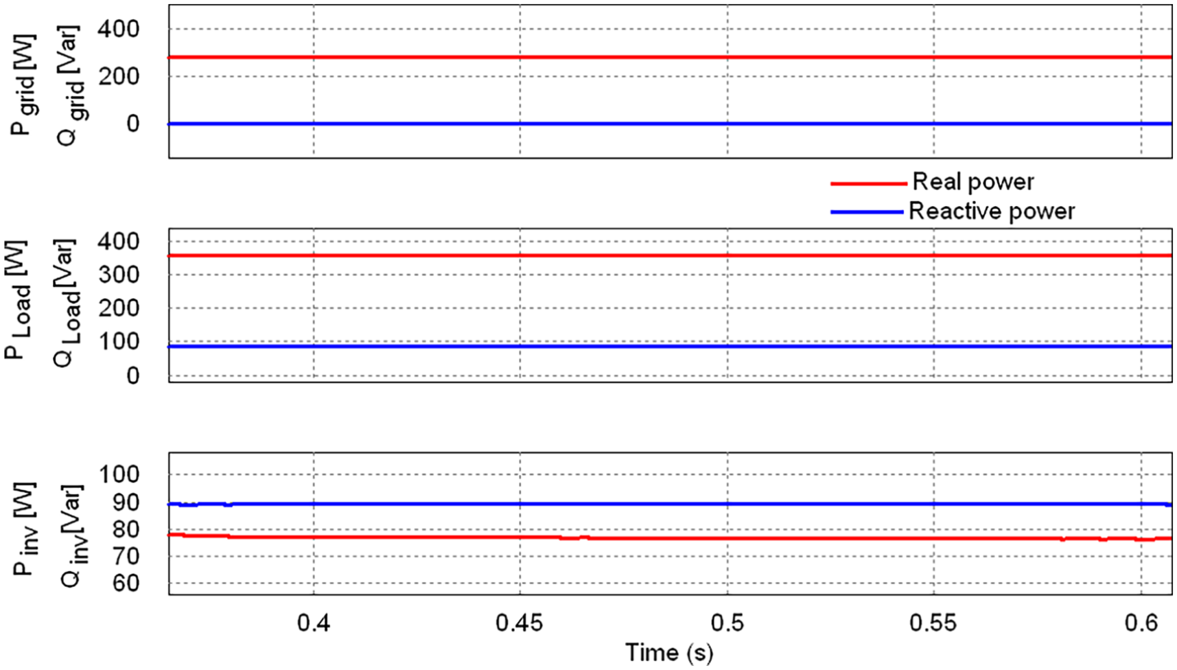
The real and reactive power profile obtained in this case is illustrated in Figure 9. For this condition, the power consumed by the load is 360 W and the power supplied by the PV module is 81 W and the balance power 279 W is derived from the grid. The reactive power consumed by the load is supplied by the grid inverter. The harmonic profile of the proposed condition of PV-APF combination system under steady state is shown in Table 5. The THD of supply voltage, supply current and load current obtained is 0.818%, 1.56% and 85.09%, respectively. Also, it illustrates that irrespective of the nonlinearity of load changes, load type and presence of distortions in load current, the grid supply is close to sinusoidal and free from distortions. The measured THD of the grid supply is less than 5% which meets the specified limits of the IEEE-519 harmonic standard.
Real and reactive power profile in real power supply with shunt active power filtering mode.
At a period t = 0.6 s (see Figure 8), irradiance is suddenly varied from 900 to 450 W/m2. Under this condition, the power supplied by the PV module is 40 W and the balance power 320 W is derived from the grid. At a period t = 0.8 s (see Figure 8), again irradiance is suddenly changed from 450 to 900 W/m2. It is noted that the DC-link voltage under this condition of sudden change in irradiance level is regulated after a period of t = 0.05 s. At a period t = 1 s, the step change in load occurs from 360 to 720 W, the response of DC bus voltage is lightly perturbed and settled with a maximum time period of 0.2 s but the PV voltage is still regulated which illustrates the proficiency of the proposed control system (see Figure 8).
The decrease and increase in the value of PV power at DC-link is conformed through decrease and increase in the value of injected inverter output current represented in Figure 8. Then, the corresponding increase and decrease in the magnitude of grid source current is characterized (see Figure 8). This represents that the grid inverter can be controlled to make it function as both real power supplier and shunt APF and mitigate power quality problems. Suitable control has been implemented for the grid-integrated PV system to extract maximum real power and to meet the reactive power demand of the system.
Figures 10–12 show the effectiveness of the variable-frequency hysteresis-based SMC-MPPT boost converter connected with grid environment employing nonlinear loads. From the results, it is to be found that the transition from different operating regions is characterized but the PV voltage is not well regulated fast (see Figure 10). The dynamic and steady-state response of the PV system is poor and introduces more chattering magnitude and the maximum available PV power is not fully transferred to grid. The comparison results of both the systems are illustrated in Tables 6 and 7, respectively. The harmonic profile of the proposed PV-APF combination system is shown in Table 5. The THD of supply voltage, supply current and load current obtained is 0.90%, 2.48% and 85.32%, respectively, for the same load condition operated by the fixed-frequency PWM-based PV-APF combination system described previously.
Resultant waveforms of grid source voltage, grid source current, load current, inverter output current and DC bus voltage with variable-frequency SMC-MPPT operation during steady state (Rd1 = 15 Ω and Ld1 = 3 mH).
Dynamic response of grid source current, load current, inverter output current, DC bus voltage, PV voltage and PV current with perturbation in irradiance and step variation of nonlinear load (Rd = 30 Ω to Rd1 = 15 Ω and Ld1 = 3 mH).
Real and reactive power profile under variable frequency hysteresis-based SMC-MPPT.
Comparison results of two controllers for PV-MPPT application (MPPT and grid efficiency)
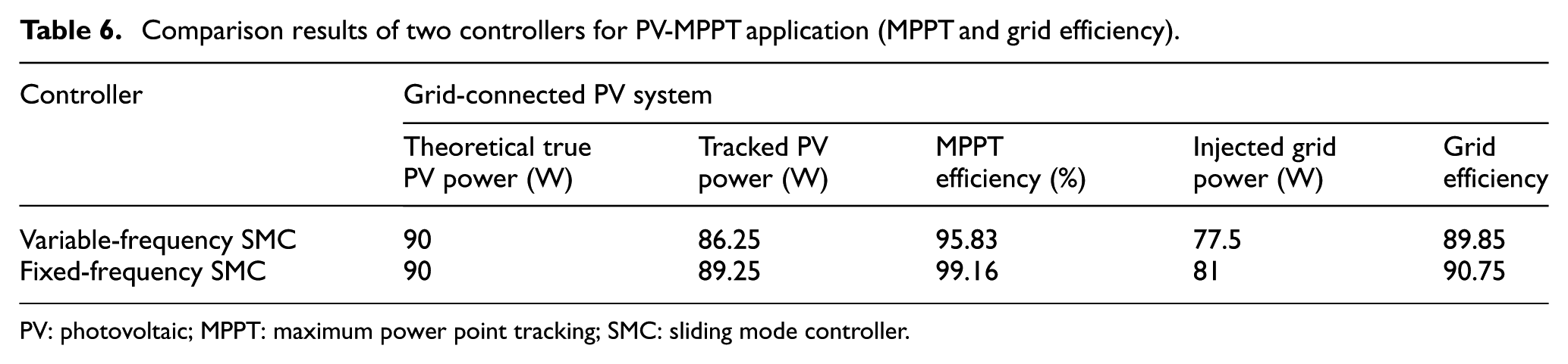
PV: photovoltaic; MPPT: maximum power point tracking; SMC: sliding mode controller.
Comparison results of two controllers with PV-MPPT application (settling time, chattering magnitude and peak overshoot)
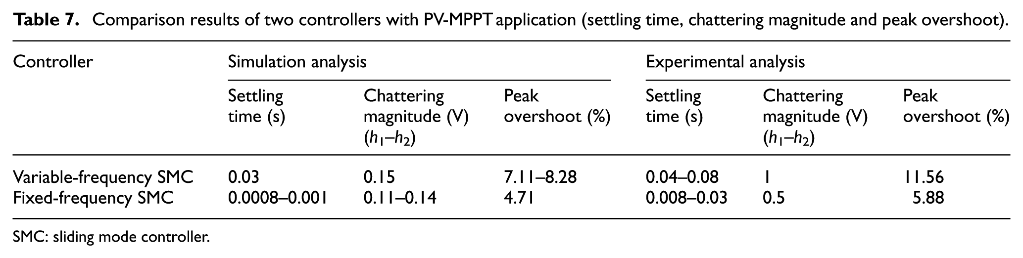
SMC: sliding mode controller.
Figure 13 shows the simulated response of PV current and PV voltage using fixed-frequency PWM-based SMC-MPPT with decreased value of irradiance from 900 to 400 W/m2 at time t = 0.6 s. When the irradiance decreases, the PV current decreases simultaneously but the system voltage reaches a steady state after a small transient period of approximately 0.001 s maximum (see Figure 13). An experimental hardware prototype is constructed in laboratory in order to check the proficiency of the fixed-frequency SMC-MPPT converter operation.
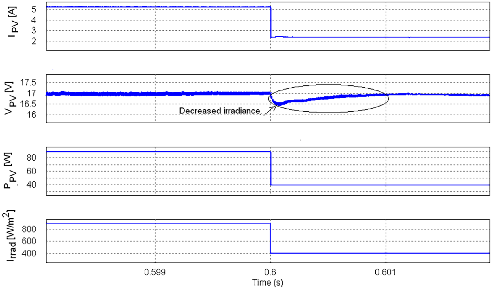
Simulated transient response of PV current, PV voltage and PV power with variable irradiance using fixed-frequency SMC-MPPT operation.
Figure 14 shows the experimental behaviour of the PV voltage and current which is obtained by fast irradiance variation, which confirms the simulations presented in Figure 13. When the irradiance decreases or increases, the PV current decreases or increases simultaneously but the system voltage reaches a steady state after a small transient period of approximately 0.03 s (see Figure 14). Similarly, Figure 15 shows the experimental response of the PV voltage and current which is obtained by fast irradiance variation using variable-frequency SMC-MPPT converter. The response time is poor (0.08 s maximum) and introduces more chattering in this case (see Figure 15).
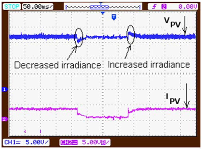
Experimental response of PV current and PV voltage with fast irradiance variation (fixed-frequency PWM-based SMC-MPPT operation).
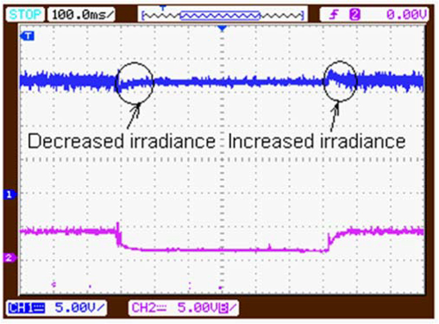
Experimental response of PV current and PV voltage with fast irradiance variation (variable-frequency hysteresis-based SMC-MPPT operation).
Figure 16 shows the generated gate pulse and corresponding PV voltage of variable- and fixed-frequency SMC-MPPT converter at the particular value of irradiation. Figure 16 illustrates that the variable-frequency SMC-MPPT introduces more chattering magnitude when compared to fixed-frequency SMC-MPPT. Table 7 illustrates the comparison results of two controllers with PV-MPPT application. The results are obtained under the condition of 900 to 200 W/m2 with the temperature of 25 °C. As a result, the PV system with the proposed fixed-frequency SMC-MPPT maintains stability under all range of solar irradiance.
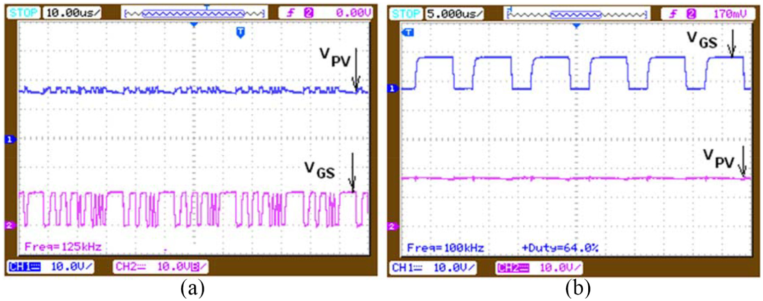
Gating signal and PV voltage: (a) variable-frequency hysteresis-based SMC-MPPT; (b) fixed-frequency PWM-based SMC-MPPT.
Conclusion
This article discusses the performance analysis of grid-integrated PV system employing nonlinear loads with fixed- and variable-frequency SMC-MPPT DC-DC converter. A simple nonlinear controller of grid inverter based on SMC not only meets the function of real power demand of load but also performs reactive power and harmonic compensation to the local load. Hence, the utility grid supplies a lesser real power demand and nearly negligible reactive power demand of the local load. This makes the grid supply current as nearly sinusoidal and harmonic free. The THD measured is within the limits of IEEE 519-1992 standards. The proficiency of the designed controller has been demonstrated against load and irradiance variations. The results of the SMC-MPPT boost converter have fast dynamic response in accordance with uncertainties in climatic and load conditions. The application of the proposed design of PV-APF combination system employing nonlinear load compensation is cost effective, simple to implement, innovative and found to work well for low- to medium-scaled two-stage grid-integrated PV system.
Footnotes
Declaration of conflicting interests
The author(s) declared no potential conflicts of interest with respect to the research, authorship and/or publication of this article.
Funding
The author(s) received no financial support for the research, authorship and/or publication of this article.