
Abstract
This paper presents the design of a fault detection and diagnosis system for a quadrotor unmanned aerial vehicle under partial or total actuator fault. In order to control the quadrotor, the dynamic system is divided in two subsystems driven by the translational and the rotational dynamics, where the rotational subsystem is based on a linear parameter-varying model. A robust linear parameter-varying observer applied to the rotational subsystem is considered to detect actuator faults, which can occur as total failures (loss of a propeller or a motor) or partial faults (degradation). Furthermore, fault diagnosis is done by analyzing the displacements of the roll and pitch angles. Numerical experiments are carried out in order to illustrate the effectiveness of the proposed methodology.
Keywords
Introduction
Unmanned aerial vehicles (UAVs) are gaining more and more attention in recent years due to their important contribution and profitable application in various tasks such as surveillance, search, rescue, remote sensing, geographical studies, as well as various military and security applications. 1 The most popular UAVs are fixed-wing and multirotor UAVs (helicopters, quadrotors, hexacopters, among others). Fixed-wing aircrafts can fly forward at high speed and are suitable for long distances due to their configuration, which makes the energy consumption less than a multirotor. Nonetheless, they cannot take-off and land vertically. 2 However, multirotor vehicles can take-off and land vertically and stay in a hover position, which could be very convenient for some applications such as surveillance, precision farming, power-line autonomous inspection, and delivering. This work is focused on the study of quadrotors UAV. A quadrotor UAV is a simple, affordable, and easy-to-fly system that has been widely used to develop and implement guidance methods, navigation control, fault diagnosis, fault-tolerant control, among others. Many research works focus on the search for techniques that guarantee stability, control, and robustness. However, the increase in civil applications makes necessary to consider new and difficult situations regarding the vehicle’s safety, for example, flying in an urban environment where the security is a critical target to achieve. For such reason, it is necessary to develop new robust fault detection and isolation systems which guarantee the security of the UAV during the all-time fly envelope. 3 The studies on fault diagnosis and fault-tolerant control for quadrotors were reviewed in Zhang et al., 1 where it is shown that these works can be divided into different types according to faults, testbeds, frameworks, problems considered, and tools employed.
Robust and efficient fault diagnosis systems require mathematical models that represent the dynamic behavior of the UAV subject to aerodynamic and measurement disturbances. It is well known that the best representation of such systems is driven by a set of nonlinear ordinary differential equations. Nonetheless, it is also known that nonlinear systems are complex and difficult to study, which reduces their applicability.
4
An attractive alternative to represent nonlinear dynamics is through linear parameter-varying (LPV) systems, which are a class of linear systems whose state space matrices depend on a set of time-varying measured or estimated parameters.
5
The idea of controlling LPV systems has been introduced in Kamen and Khargonekar,
6
then further extended during the last two decades to produce many control methods and for fault detection. Examples of these methods include observers,
7
fault-tolerant controllers,
8
Among the different classes of LPV systems, the quasi-LPV (qLPV) systems have become of importance in the last years due to the fact that the nonlinearities are hidden (or embedded) in the varying parameters, in this case the varying parameters depend on exogenous signals. 11 This work considers this class of LPV systems.
The qLPV systems are an alternative for the representation of nonlinear systems used to address problems such as fault detection and control. In that same sense, some recently highlighted works are as follows: Dahmani et al. 12 presented a robust observer to estimate the dynamics of a vehicle evaluated through an experimental configuration; Aouaouda et al. 13 proposed an active fault-tolerant tracking controller (FTTC) scheme applied to a vehicle dynamics system. The stabilization problem of qLPV systems is addressed in Wag et al., 14 where a controller is designed to guarantee the stability of a closed-loop system. Also, Hu et al. 15 proposed an output-feedback control strategy for the path following of autonomous ground vehicles.
More recently, qLPV has been considered for the study of UAVs, specifically to represent its dynamics and for the construction of fault detection systems. For instance, a fault detection based on an unknown input LPV observer in discrete-time for a helicopter is presented in De Oca et al.; 16 in that same sense, a fault detection and isolation method using set-valued observers was proposed in Rosa and Silvestre 17 for a fixed-wing aircraft. Aguilar-Sierra et al. 18 proposed a fault estimation method by considering polynomial observers. The use of the Lyapunov quadratic function in LPV systems to control and stabilize aerial vehicles is presented in Sadeghzadeh et al. 19 A fault reconstruction method by considering a sliding mode LPV observer was proposed in Chandra et al. 20 A multi-level method combining dynamic control allocation and control reconfiguration was presented in Péni et al. 21 Tan et al. 22 proposed a robust fault detection method in a discrete-time qLPV system for the longitudinal movement of an UAV. Rotondo et al. 4 presents an LPV observer for diagnosing sensor faults, and this observer has the advantage of not being noise-sensitive. A fault estimation scheme in actuators of a helicopter is presented in Liu et al., 23 which reduces the impact of the transient phenomenon. The problem of fault detection and isolation has been addressed mostly in sensors. Nevertheless, application to actuators faults has not been fully investigated. One of the particular interests is the work of Rotondo et al., 11 which develops a robust qLPV fault-tolerant control subject to actuator faults with very good performance, however; the proposed solution is in the order of thousands of gains, which are difficult to handle in a real-time implementation. This implies a challenging and open problem. Therefore, the objective here is to develop an effective actuator fault detection and isolation method simplifying the complexity of the solution.
This paper presents an actuator fault detection and isolation method based on an observer for a quadrotor UAV modeled as a qLPV system. The main contribution of this work is the use of a robust
This paper is organized as follows: the next section presents the preliminaries on qLPV systems; the “Dynamic model and problem definition” section presents the mathematical model of the quadrotor and its qLPV representation; the “Main result” section presents the linear quadratic regulator (LQR) controller used to stabilize the system, the observer design, and fault detection in actuators, where the convergence of the robust observer is guaranteed by Lyapunov functions and a
Preliminaries on qLPV systems
The sector nonlinearity approach 24 is used to construct the qLPV model for a given nonlinear system. Considering a nonlinear system of the form
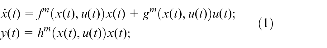
where
The non-constant terms of the nonlinear system are grouped into the scheduling functions
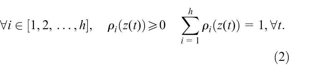
The nonlinearities of the system are considered as variant parameters, so that they are involved in weighting functions, given by
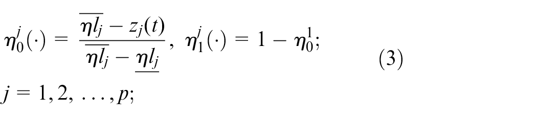
where
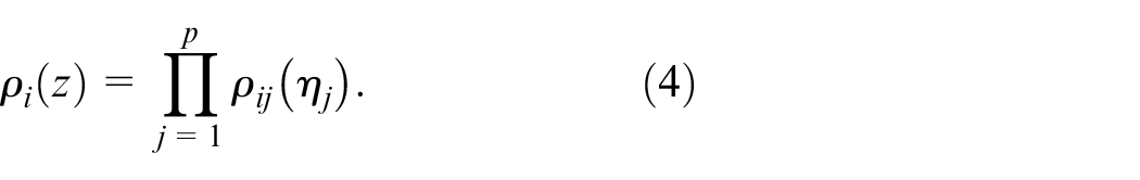
Then, by considering equation (4), the nonlinear system (equation (1)) is represented by the qLPV model
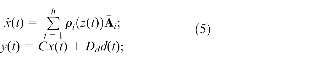
with
Dynamic model and problem definition
Nonlinear representation
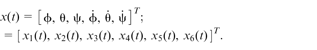
The quadrotor UAV configuration is shown in Figure 1. The state vector of the quadrotor is
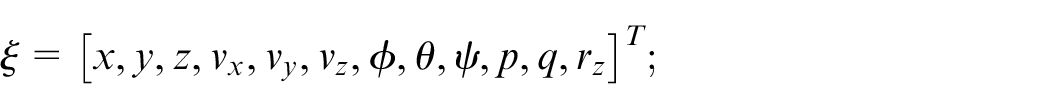
where
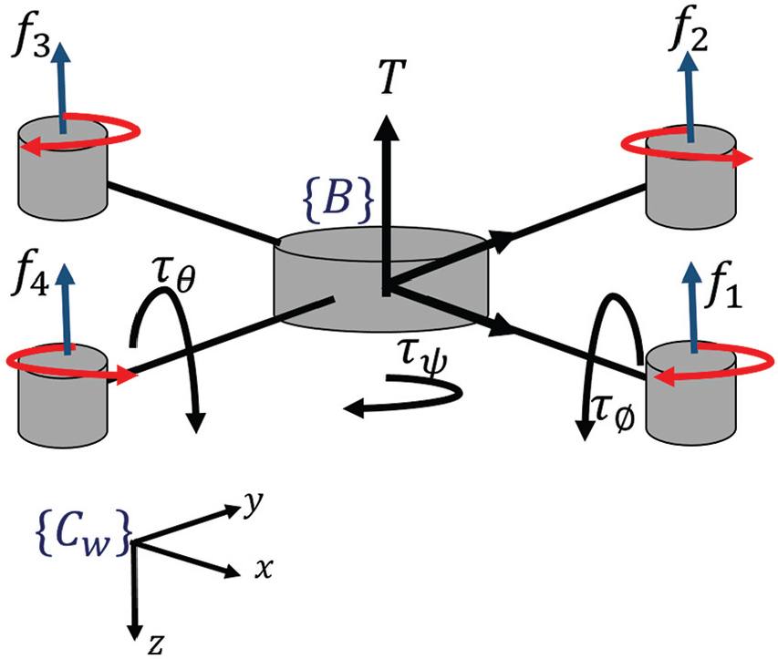
The quadrotor UAV configuration.
By considering the Newton–Euler formalism,25,26 the nonlinear model is obtained as
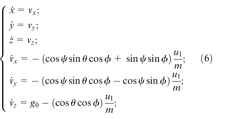
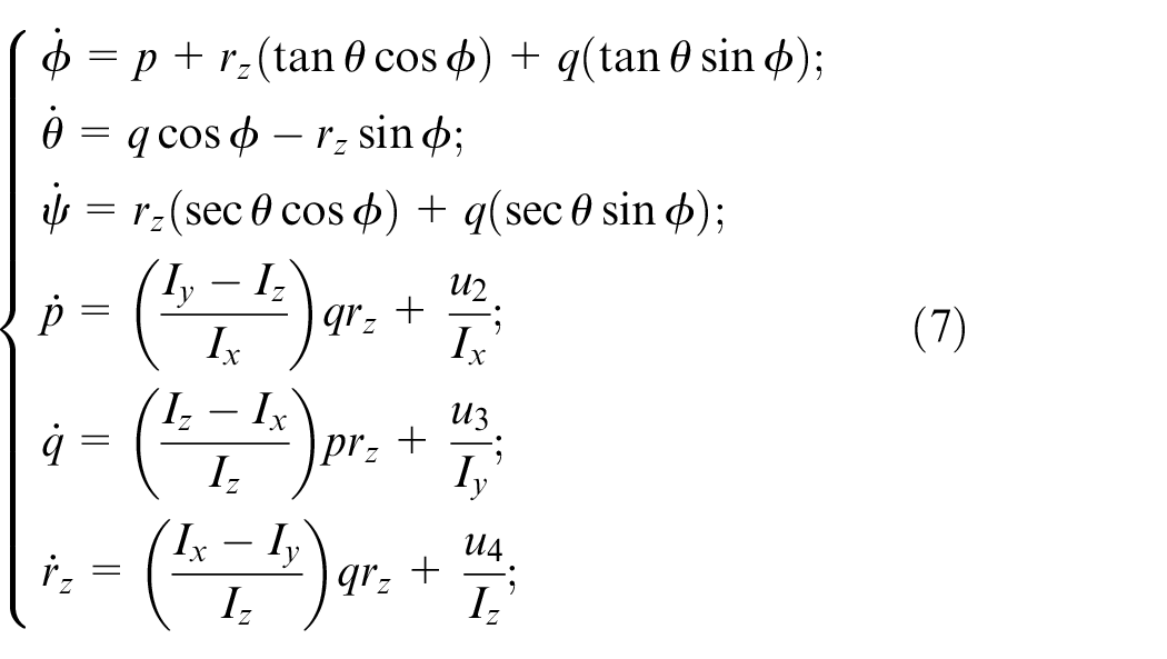
where
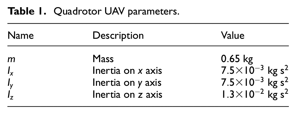
Quadrotor UAV parameters.
Subsystem (equation (6)) represents the translational dynamics and subsystem (equation (7)) represents the rotational dynamics over the reference frame
The control inputs u are defined in terms of propeller angular speeds. The four inputs comprising the total thrust, roll, pitch, and yaw torques are
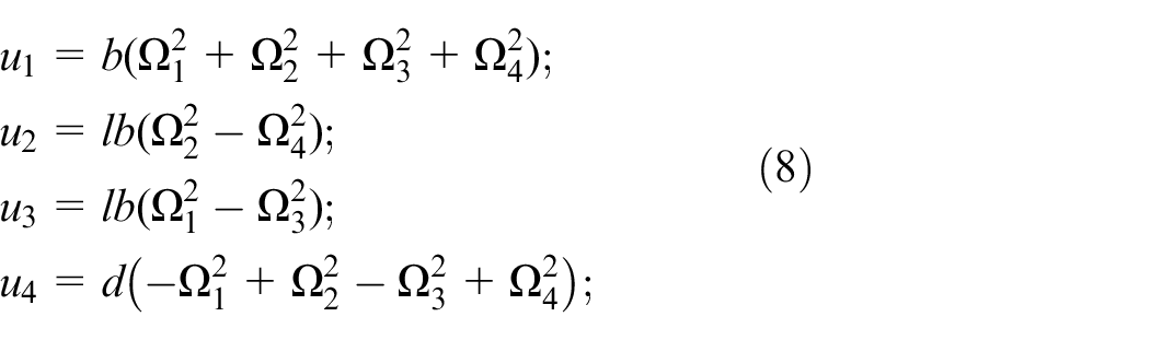
where l is the distance from the center of mass to the rotors, b and d are the thrust and drag factors, respectively, and
It is noteworthy that the control inputs
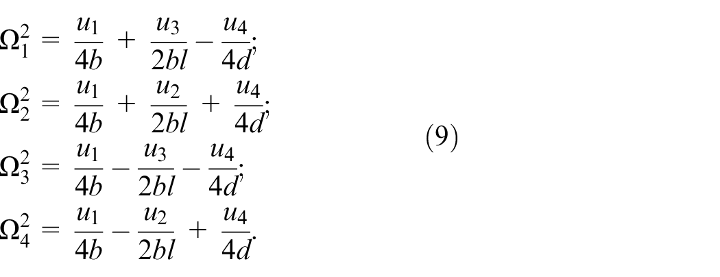
This consideration is necessary for the numerical experiments in order to induce actuator faults in the UAV, which can be observed with respect to changes on the angular speeds for the ith rotor. Furthermore, in order to design the fault diagnosis algorithm, the following section presents the characteristics of a qLPV model and identifies the terms required to obtain a qLPV representation the system (equation (7)).
qLPV model
Two subsystems describe the dynamics of the quadrotor, one describes the translational part (equation (6)) and the other describes the rotational part (equation (7)). It is possible to study them separately due to the fact that they are decoupled. This property will be used to detect an actuator failure because the pitch, roll, and yaw angles change dramatically in the presence of a rotor failure. The state vector of the rotational dynamics (equation (7)) is defined as
The inputs are
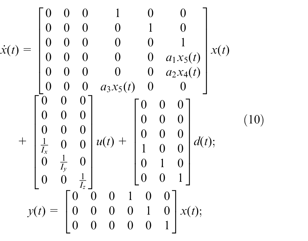
where
As it can be seen from the system (equation (10)), matrix
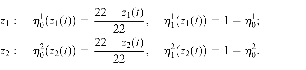
The limits of the weighting functions are
From the representation of the system (equation (5)), its LPV representation is obtained
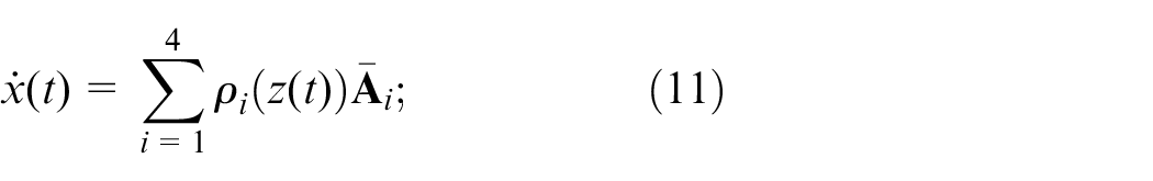

with
The
Main result
Controller design
A control strategy for stabilizing the quadrotor while hovering is necessary as this is an open-loop unstable system. The translational dynamics and the yaw angle are controlled by an LQR controller. The objective of this controller is to determine control signal so that the system to be controlled can meet physical constraints and minimize/maximize a cost/performance function. In this case, R is the cost of actuators, which is defined by the designer. The controller is not presented here due to space limitations. However, this can be consulted in Reyes-Valeria et al. 28 Then, for the remaining of the paper, it is considered that the UAV is stabilized.
Observer design
Assuming that system (equation (12)) is observable, the following fault diagnosis LPV observer is proposed
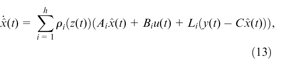
where

The error dynamics is computed as
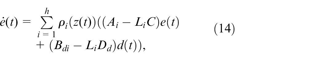
and the residual state space error system is given by

where W is the residual weighting matrix that has to be determined.
Then, the problem is reformulated to ensure stability of asymptotic equations (14) and (15) despite the perturbation vector
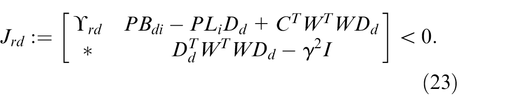
Theorem 1
The robust observer (equation (13)) for system (equation (5)) exists if there exist matrices
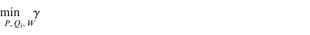
under the following LMI constraints
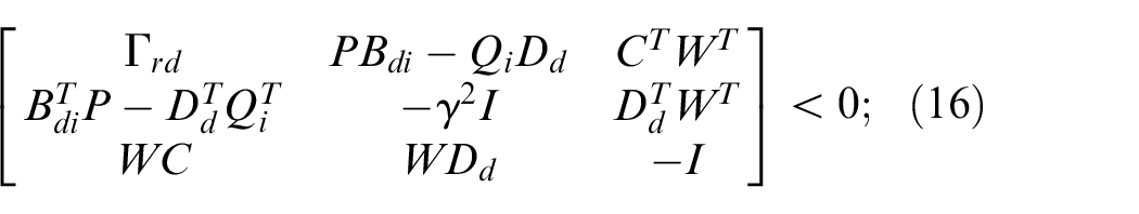
with
Proof
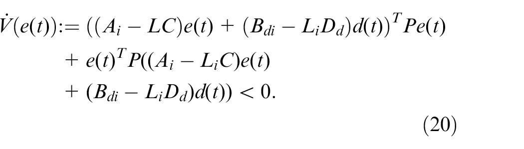
In order to guarantee asymptotic convergence of the estimation error to zero and robustness against disturbances


where

By substituting equation (14) in equation (19), the following is equivalent
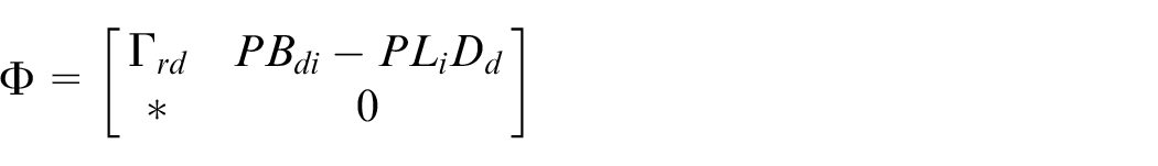
After some algebraic manipulation, the following is obtained
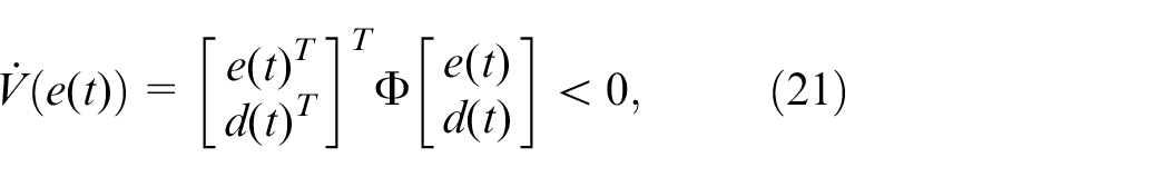
with
and
By manipulating equation (18), the following is obtained
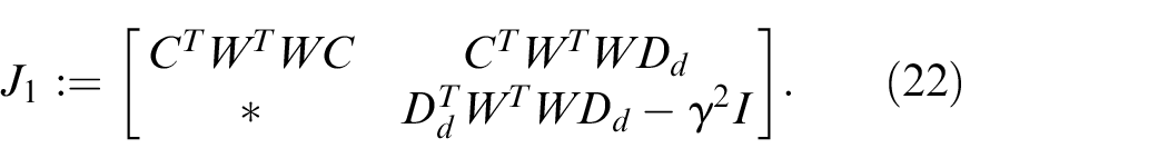
By considering equations (21) and (22), the condition (17) is rewritten as
Then,
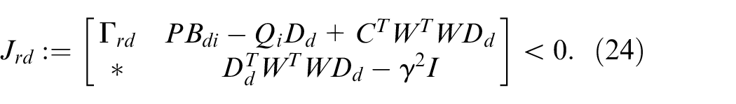
Finally, the Schur complement implies equation (16). This completes the proof.
Actuator fault detection and diagnosis
The faults considered are additive faults; this is because most of the faults in actuators are deviations of the signals (bias) due to a stop or increase/decrease in the rotors velocity, damage in the propellers, malfunction of the electronic speed controllers, among others. The model-based fault detection and diagnosis method designed on this section is based on the approach presented in Saied et al. 29 First, residual signals based on a robust state-observer, for the rotational subsystem (equation (7)), is generated in order to compare the expected behavior of the system with the measured one. These residuals are defined as the differences between the measured angles given by the inertial measurement unit (IMU) of the UAV and the estimated angles, which are the system and the observer outputs, respectively. The residuals are defined as
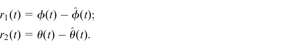
Once the residuals are generated, they are analyzed in order to detect and isolate faults in the actuators. In a fault-free case, the residual
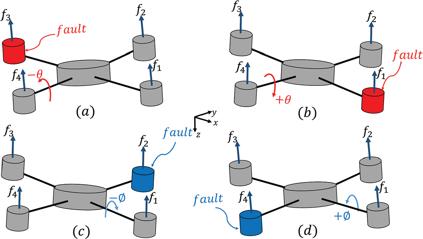
Displacement fault indicator for: (a) actuator 3; (b) actuator 1; (c) actuator 2; (d) actuator 4.
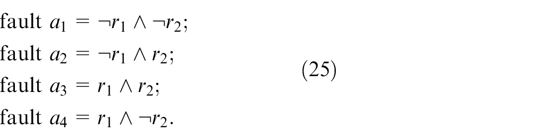
Therefore, given the residuals
Diagnosis inference model for one actuator fault.
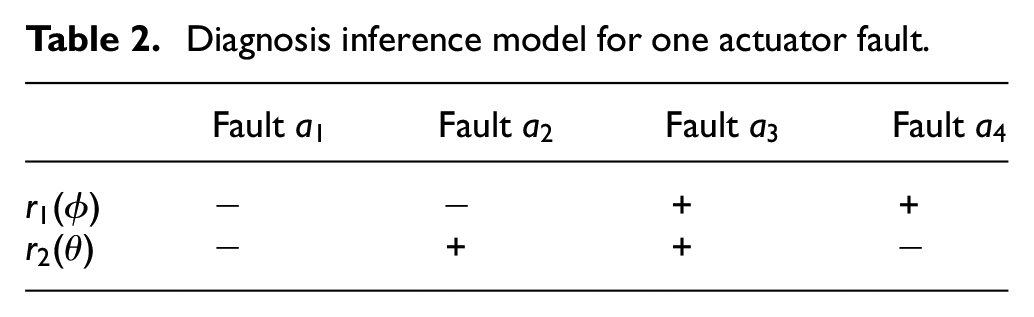
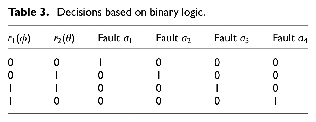
Decision-making is done through a scheme of binary logic by substituting negative and positive displacements
where
Decisions based on binary logic.
Numerical results
This section presents numerical tests in order to show the effectiveness of the fault detection and diagnosis method.
Observer synthesis and controller test
For the synthesis of the proposed LPV observer with
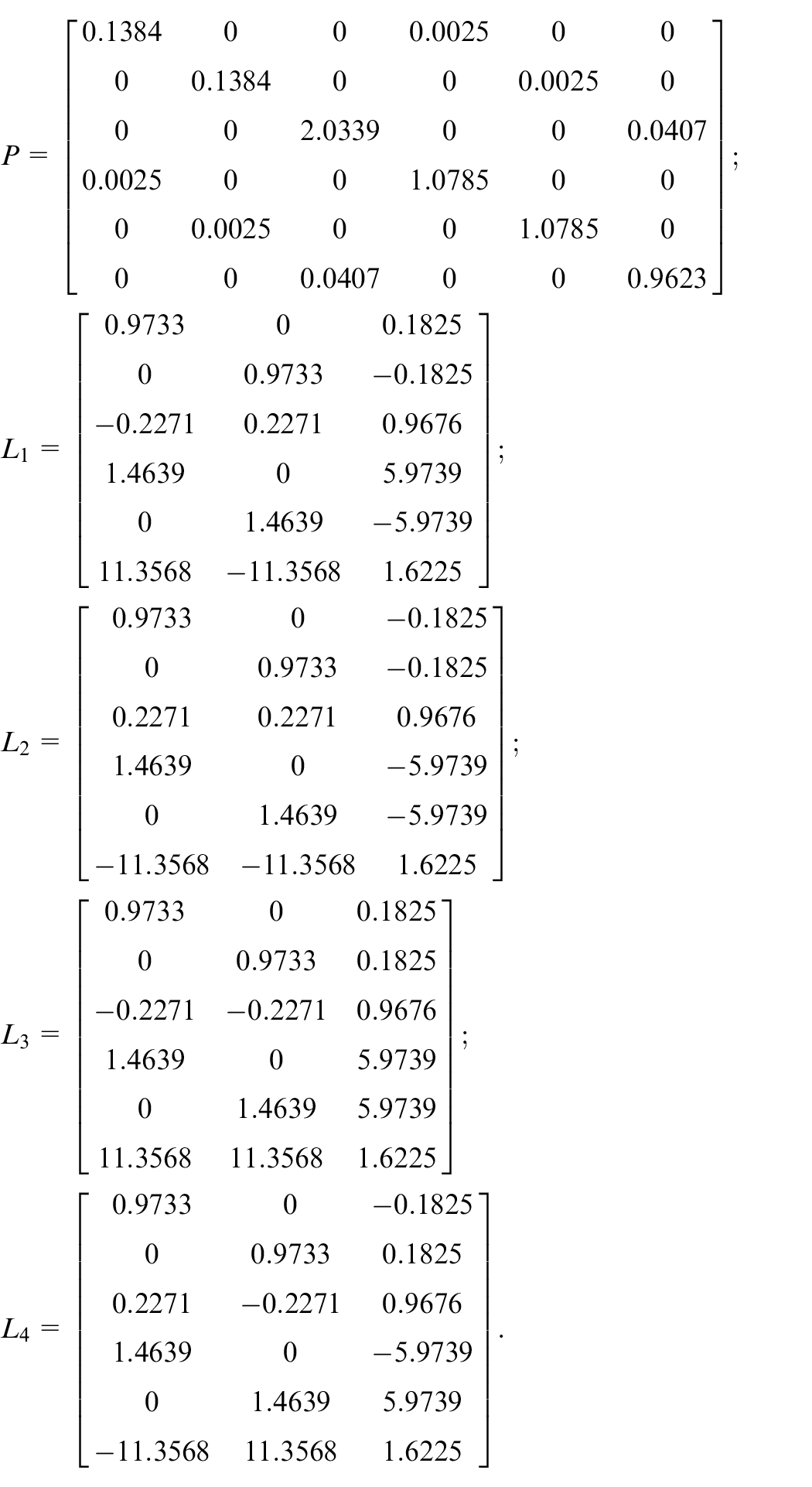
The attenuation level obtained is
Once the observer is designed, the system’s performance is tested in closed-loop using the LQR controller designed for the stabilization of the quadrotor. The numerical experiments were performed in MATLAB®/Simulink®.
Figure 3 shows the references in dashed line and the tracking trajectory in solid line. The tracking trajectories were obtained thanks to the LQR controller. A three-dimensional (3D) representation is illustrated in Figure 4, where the three graphs presented in Figure 3 are combined. The trajectory obtained follows the reference, so the LQR controller fulfills its purpose. The resulting trajectory is described below with the help of points in the path:
At
The path continues to the point
At
The trajectory of the quadrotor comes back to
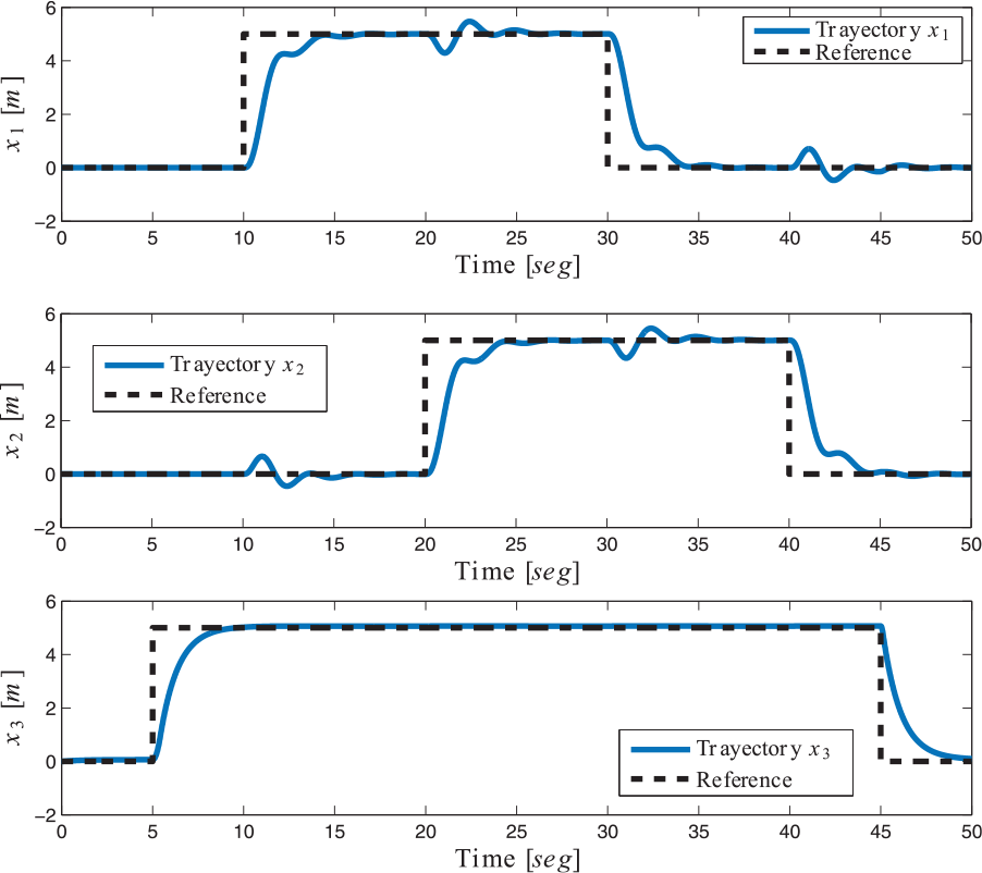
Reference and tracking entries obtained.
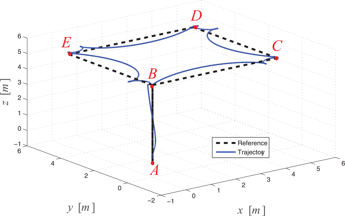
Tracking and reference in 3D space.
Fault detection and isolation
The numerical experiments begin once the quadrotor has been stabilized in hover flight mode. In order to test the effectiveness of the proposed method, two different scenarios are considered, partial and total faults. In all cases, the observer is fed with noisy measurements of the system input/output. The following describes each case.
Partial fault
In this scenario, three different types of faults are induced to actuator 3. For the first fault, the magnitude of the control signal of the actuator required to stabilize the UAV in hover flight mode is reduced by 20% in
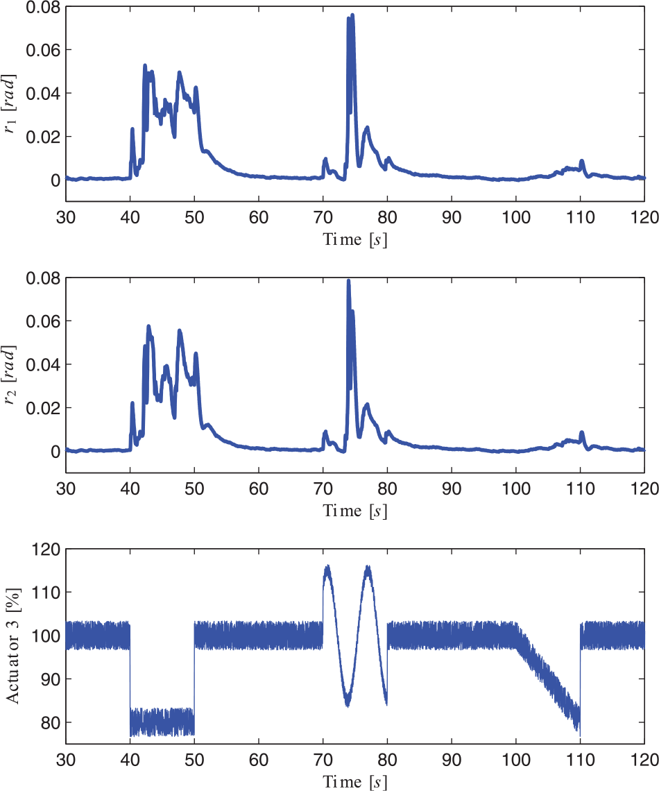
Residuals with partial fault and faults induced to actuator 3.
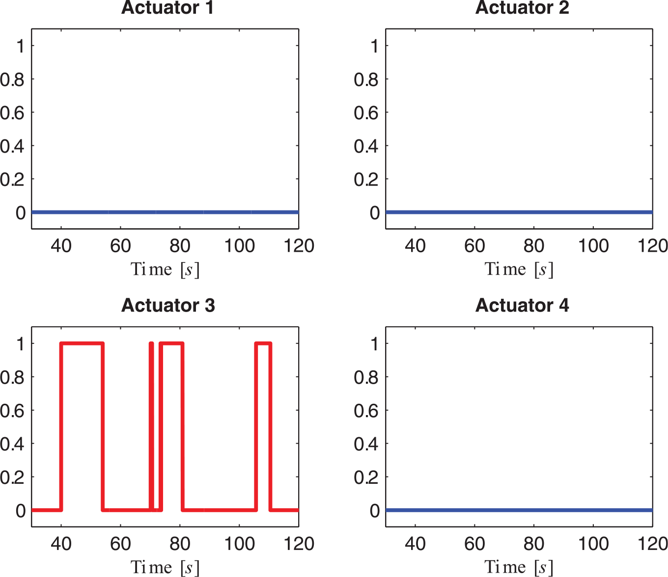
Partial fault diagnosis on actuator 3.
Total fault
A total fault is induced by turning off the actuator 3 at
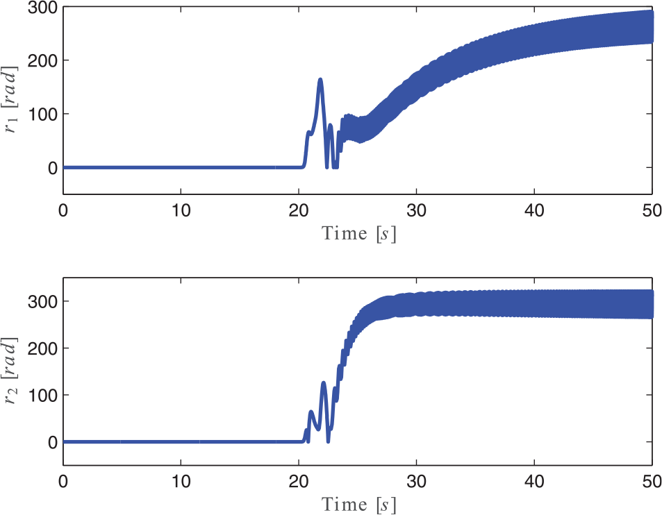
Residuals with total fault on actuator 3 at
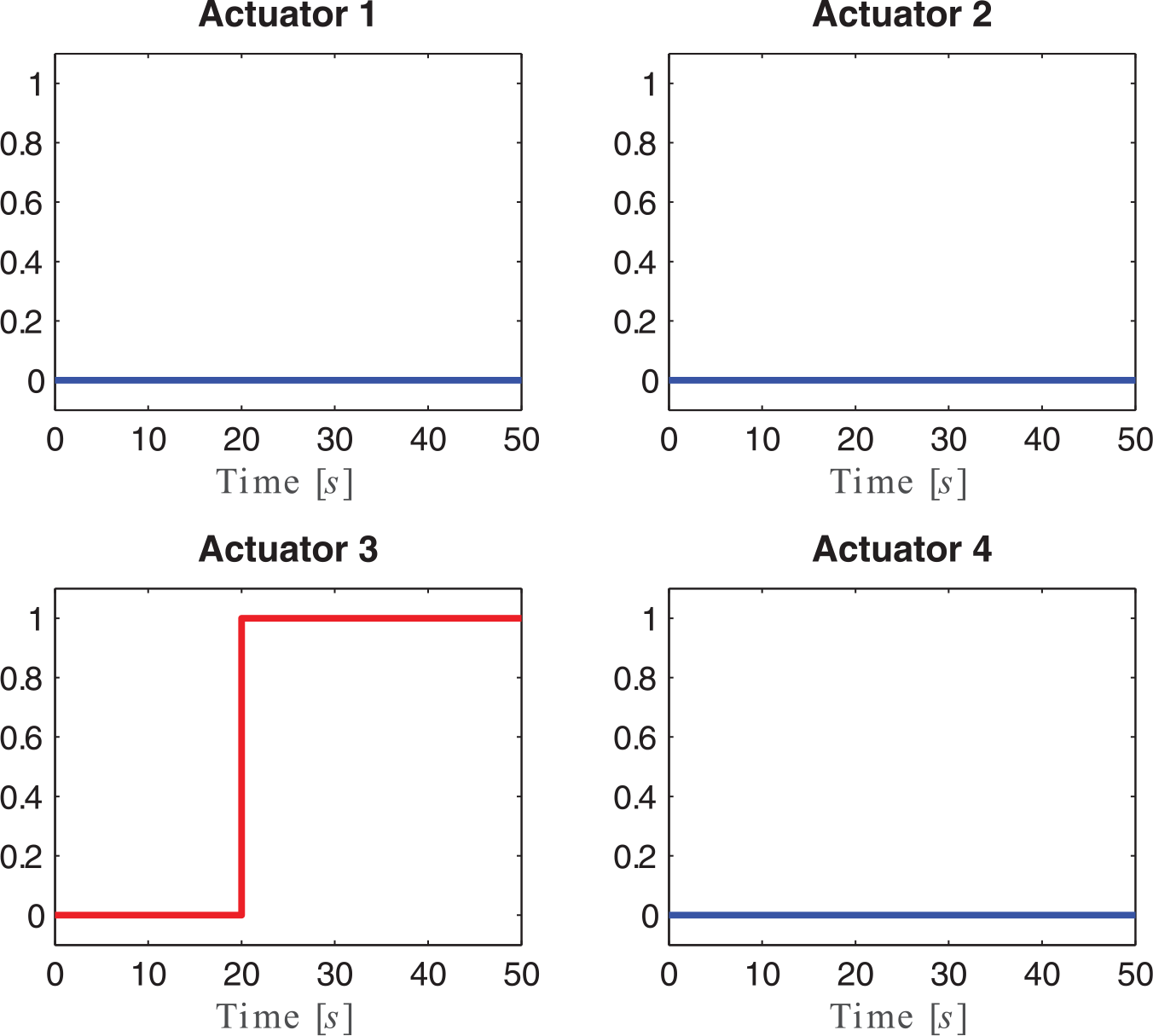
Total fault diagnosis on actuator 3.
Comparisons
To complement the results, Figure 9 shows the comparison between the approach of Rotondo et al. 11 and the approach proposed in this paper. Specifically, the figure shows the alarms of actuator 1 for a partial fault scenario. The induced fault consists in a reduction of the control signal of the actuator from 100% to 70%. It can be seen that both approaches have the same performance as they activate the alarm when the fault occurs.
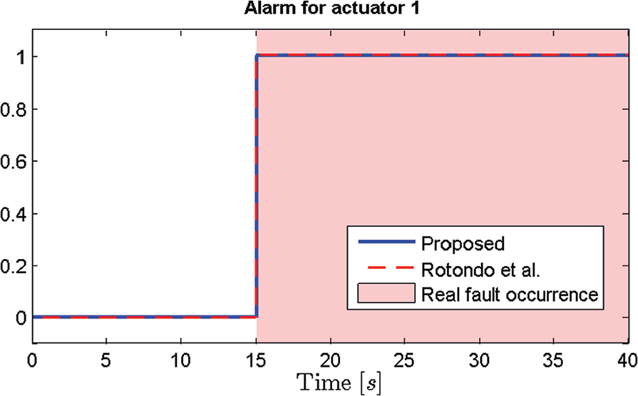
Alarms for actuator 1 in partial fault scenario.
The difference between the approaches is mainly that Rotondo et al.’s 11 work considers the complete quadrotor model, while in this work, the fault detection and isolation are only applied to the rotational dynamics. Considering the complete model also implies that more residues must be taken into account for the fault detection and isolation, and therefore, the inference matrix is larger and its online analysis is more complex; although, it is also acknowledged that faults can be also detected and isolated while the UAV is moving in the space, not only in hover flight mode. Moreover, although the computation of the optimization problem (equation (16)) is performed offline, it is always important to analyze its complexity since the time needed to solve the LMI grows exponentially as the problem dimension grows. In this case, the LMI dimension is smaller than the one presented in Rotondo et al. 11 Furthermore, it is well known that the LMI problem could become unfeasible as the number of vertices grow. In the approach presented here, the number of vertices is reduced (four vertices) since the method has been applied to the rotational dynamics of the quadrotor only, while in Rotondo et al., 11 the number of vertices exceeds 2000, leading to an equal number of gains Li’s that have to be considered online. Clearly, the method presented here is easier to handle and implement in a real application.
Comment on stability in case of an actuator failure
Quadrotors are open-loop unstable systems and depend on a controller for their stabilization. Therefore, the stability analysis depends mainly in the controller which is out of the scope of this paper. Nevertheless, it is important to remark that, in a faulty situation, the controller may not be able to stabilize the system, depending on the severity or intensity of the affectation. If the fault is partial and with very low intensity, a conventional controller may be able to stabilize the system regarding the fault as a model mismatch or disturbance. For a more severe affectation, there are also passive/active fault-tolerant control strategies reported in the literature that increase the actuator affectation tolerance.31–33 If the fault in one actuator is total, an emergency protocol has to be activated such as the use of a parachute; another option may be to give up controlling the quadrotor’s yaw angle, and use the remaining actuators to achieve a horizontal spin. 34 Although with a very low probability, two (opposed) or three actuators can fail simultaneously and a specific control law is required for those scenarios.35,36
Conclusion
This paper presented a robust fault diagnosis and isolation scheme for actuator faults of a quadrotor UAV modeled as an LPV system. In order to detect partial or total actuator faults, a residual was generated using a
Footnotes
Declaration of conflicting interests
The author(s) declared no potential conflicts of interest with respect to the research, authorship, and/or publication of this article.
Funding
This work was supported by the Tecnológico Nacional de México (TecNM) under the program Apoyo a la Investigación Científica y Tecnológica (grant numbers 6210.17-P and 6723.18-P). Additional support was provided by the Consejo Nacional de Ciencia y Tecnología under the program Cátedras Conacyt (project number 88).