
Abstract
This paper proposes an aerostatic lubrication model with the use of finite difference method, and the solution of the model is designed with the combination of flux error feedback and grid parameter optimization. The model and solution are validated by the performance test on the slider with the diameter of orifice at 50 and 200 μm. Finally, the proposed model is applied to the optimal design of the aerostatic turntable, and the type, parameter and configuration of the restriction are determined by the optimal results. To guarantee the accuracy of key parts, the ultra-precision turning technology is applied to manufacture of turntable, and the runout of the end face meets the design requirements through the verification. The proposed model and solution are significant to the analysis and design of high-performance aerostatic equipments.
Introduction
Nowadays, the ultra-precision machining and measurement technologies are rapidly developed, 1 and the accuracy of ultra-precision machining and measuring equipment with rolling and hydro bearings fails to satisfy the requirements. Due to the high motion accuracy and thermal stability, aerostatic bearings are widely used in precision engineering, while the low load and stiffness limit their further application in heavy load conditions. Therefore, how to improve the load and stiffness is the one of the key problems in the researches on aerostatic bearings.2–4
For the aerostatic bearing model, the model with orifice restriction was studied early by Wang 5 and Chi 6 found that the pressure distribution of gas film is conformed to Reynolds Equation. Al-Bender 7 introduced on one hand an overview of the methods used to model the dynamic characteristics of aerostatic films, deducing that the method of harmonic perturbation is often sufficient in providing a good estimate of the dynamic stiffness. Schenk et al. 8 presented an analytic model for the calculation of circular high-vacuum compatible gas-bearing pads with arbitrary feedings. Mondal et al. 9 introduced a simple perturbation flow model, which is formulated and validated by a rigorous computational fluid dynamics (CFD) study for designing a counterbalanced vertical-axis aerostatic thrust bearing. Li et al. 10 established the mathematical model for optimization considering both stiffness and dynamic stability, and several cases of optimization are performed under different given loads. Chang et al. 11 and Cai et al. 12 researched the influence of the orifice restriction coefficient on characteristics of aerostatic bearings and obtained the dynamic characteristics of aerostatic bearing guideway. In recent years, the software of the fluid analysis was utilized to the simulative analysis on the aerostatic bearing.13–15 Those models in above researches are built on the CFD or some other traditional methods; however, the aerostatic lubrication model in this paper is designed based on the combination of flux error feedback and grid parameter optimization.
For the manufacturing of gas lubricant instruments, Zhang et al. 16 designed a single-orifice thrust bearing with the orifice diameter at 200 μm, and the static characteristics of the bearing were better than those of the Hexagon thrust bearing. With the consideration of the specific manufacturing error of aerostatic bearing, Yao et al. 17 studied the static characteristics of the aerostatic radial bearing, which was researched with finite element method, and found that the load and stiffness were affected by the manufacturing errors. Zhang et al. 21 developed a four-orifice thrust bearing with elastic-section pressure-equalizing groove, and the load and stiffness of the bearing reached to 800 N and 100 N/μm, respectively. Yoshimoto and Kohno18,19 replaced the orifice with porous material, and the stiffness of bearing was 1000 N/μm when the gas gap is at 1 μm, which is 10 times than the traditional bearing’s stiffness. However, the gas gap at 1 μm was difficult to apply in manufacturing. To guarantee the accuracy of key parts, the ultra-precision turning technology is applied to manufacture of turntable in this paper. Therefore, a better performance can be obtained by the manufacture.
Series of researches on the theory, model and manufacture of aerostatic bearings were discussed in the above works, and the stiffness could be improved by optimizing the throttle coefficient of multiple throttles, while the structure was complex and difficult to manufacture, and the flow error caused by the pressure of cavity was usually ignored in those works. The porous material is able to effectively improve the performances of the bearing, but the cost is high and the manufacture error of the small gas has a great influence on the bearing performances. Therefore, this article improves the calculation accuracy of the aerostatic lubrication model with the flow-error feedback and optimization of grid parameter, and an optimal design on an aerostatic turntable is performed based on the proposed model, and the designed turntable is manufactured by the ultra-precision turning technology.
Gas lubricated model and solution
Based on the laws of mass, momentum and energy conversations in the field of fluid mechanics, the Navier–Stokes equations are derived. With the basic fluid-hydrostatic-lubricated assumptions, the Navier–Stokes equations can be simplified to Reynolds equations. 20 The pressure distribution of gas lubrication can be obtained from the solution of Reynolds equation. The model of single-orifice aerostatic slider is shown in Figure 1. In Figure 1, a is the radius of gas cavity, b is the half of length of rectangle-shaped slider, d is the diameter of orifice, h is the gap of gas film, p is the pressure distribution of gas film, and pa, pd and p0 are the pressures of atmosphere, gas cavity and gas source, respectively.
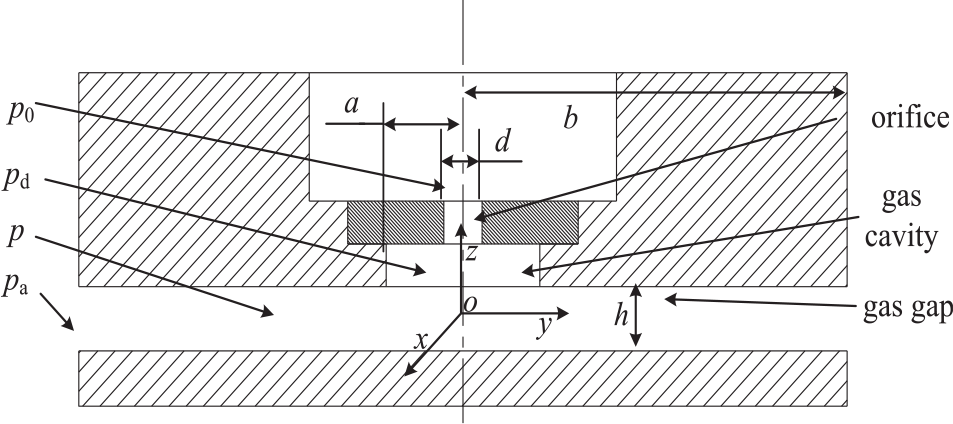
Model of single-orifice aerostatic slider.
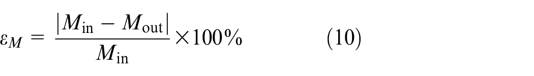
Under the condition of constant parameters, the Reynolds equation can be written as
where U and V are relative velocities in x- and y-directions, respectively; η is the dynamic viscosity.
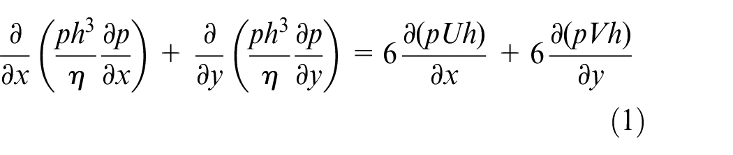
When the aerostatic lubrication is stillness, U = V =0 and F = p2, and then, Equation (1) is simplified to the following equation
where Γ is the Dirichlet boundary conditions; Ω is the internal solution domain.
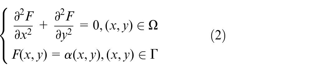
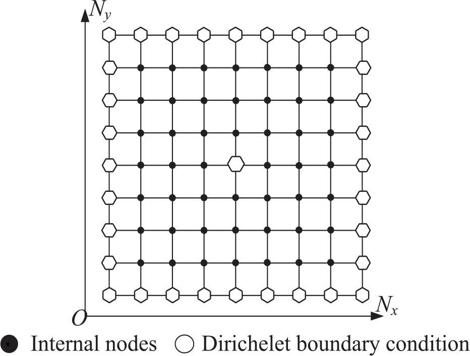
Equation (2) is a two-dimensional (2D) elliptic partial differential equation, and the difference scheme of the internal nodes is described by the finite difference method. Figure 2 shows the distribution of boundary conditions. Figure 3 presents the distribution of the nodes with number of Nx × Ny, and the domain is divided into grids with number of (Nx − 1) × (Ny − 1).
Plan form of slider.
Diagrammatic sketch of the grid.
The node spacings in the x-direction and y-direction are Δx and Δy, respectively. So, the five-point difference scheme of the internal nodes is expressed as
The nodes in the border of the gas film and gas cavity are the Dirichlet boundary nodes. The pressure is constant, and the difference scheme is given as
when the Pd is known, the distribution of pressure p(i, j) is obtained from the solution of simultaneous equations (3) and (4).
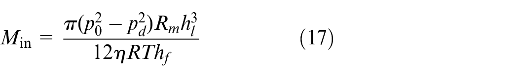
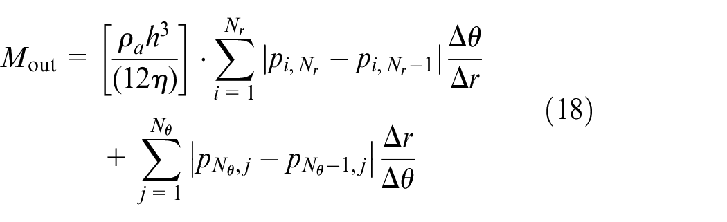
The mass flux in the border of gas film export is
where ρa is the atmosphere density and Γ a is the border of gas film export.
Based on the pressure distribution p(i, j), the difference scheme of gas film flux can be obtained in the border of the gas film with the use of difference instead of differential.
The size of the orifice is smaller than the size of gas source entry, so the gas do not flow before entering the orifice, and the time of going through the orifice is quite short, and the process can be treated as no-stick movement and adiabatic process. The flow of gas in the orifice is satisfied with the Bernoulli equation of energy conservation equations. Therefore, the flux of the orifice can be derived by
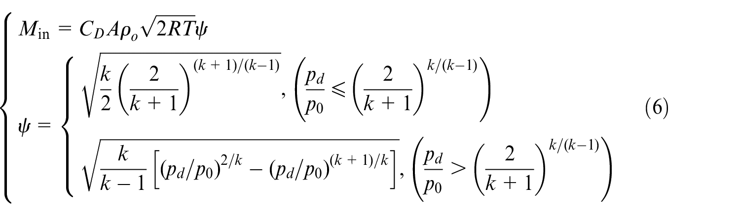
where A is the cross-sectional area of orifice restriction, CD is the throttle coefficient and the empirical value is 0.8, ρ0 is the density of gas source, R is the gas constant, T is the thermodynamic temperature and k is the isentropic coefficient and the empirical value is 1.4 for gas.
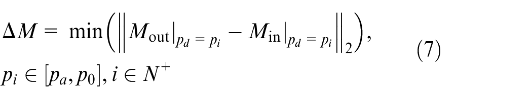
In Equations (3), (4) and (6), Pd is unknown, and its value is fixed when the gap is set. Substituting pd into Equations (3) and (4), the pressure distribution p(i, j) and the flux of entry Min are obtained. Then, the flux of gas film export Mout is obtained from the pressure distribution p(i, j). According to the principle of mass conservation, pd is the solution of Equation (6) when it makes the minimum difference between Min and Mout. The objective function is
Then, the pressure distribution is integrated over the whole surface of gas film, and the load W is given as
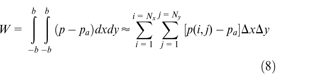
where Nx and Ny are the numbers of nodes in x- and y-directions, respectively.
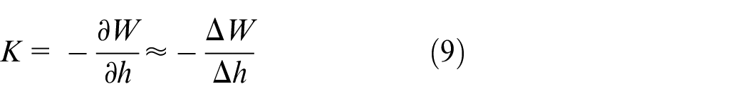
The stiffness of gas film K is obtained by the load
M out and Min are determined by pd from equations (5) and (6), respectively. In the actual flow field, the value of pd should ensure the mass-flux conservation: Mout = Min. There are errors in numerical solutions of Mout and Min, and the relative mass-flux error caused by the inaccuracy of pd is defined as
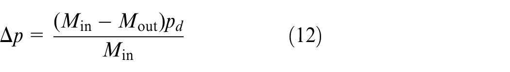
The relative mass-flux error εM is the function of pd. The more accurate pd is, and the smaller εM is. Pretending the initial value of pd is (p0 + pa)/2, its optimal value is searched in the domain of definition with the step of Δp until εM meets the accuracy requirement of ε0 which is given by

The method of variable step Δp is adopted to improve the efficiency of the searching process, and the value of step is determined by the value of mass-flux error. Therefore, the lager the error is, the bigger the step is. The Δp is defined as
As explained in the method before, the process to get the solution of flow field is shown in Figure 4.
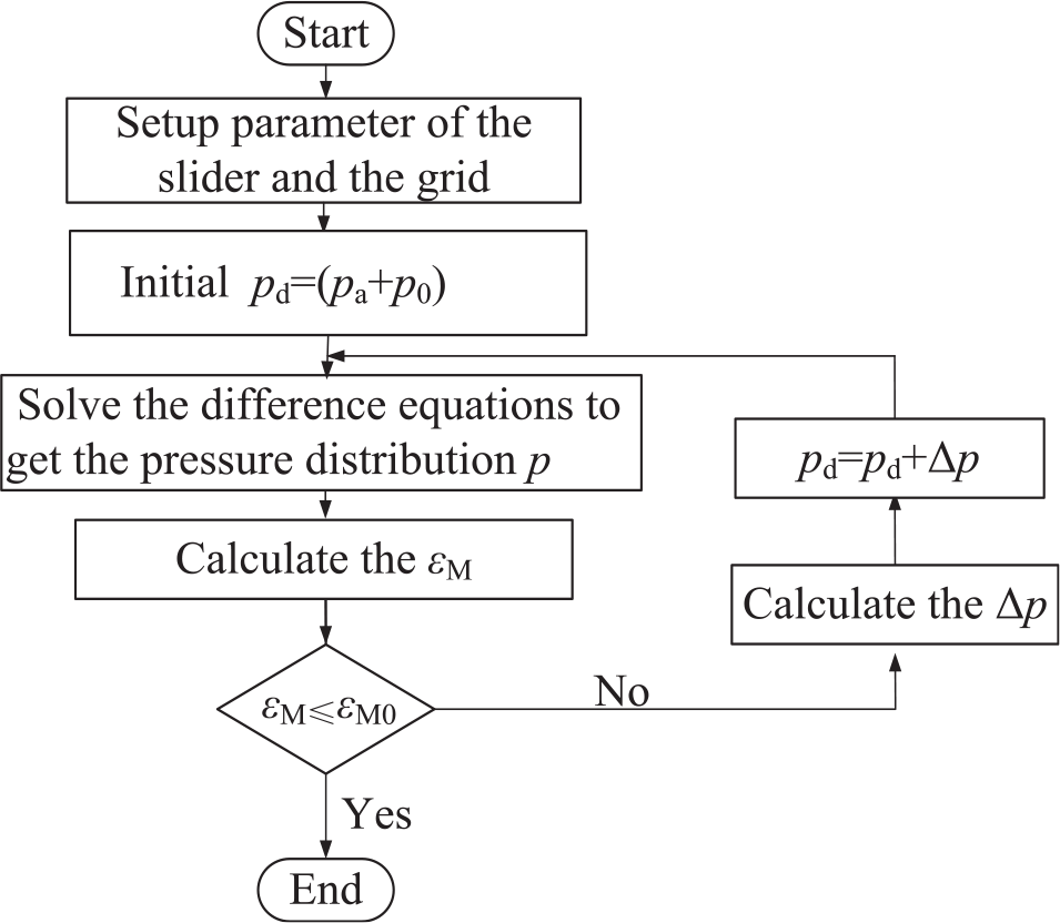
Process of solving the flow field pressure distribution.
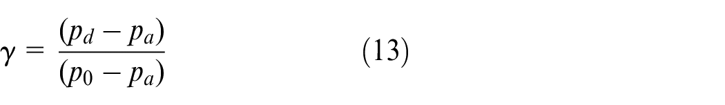
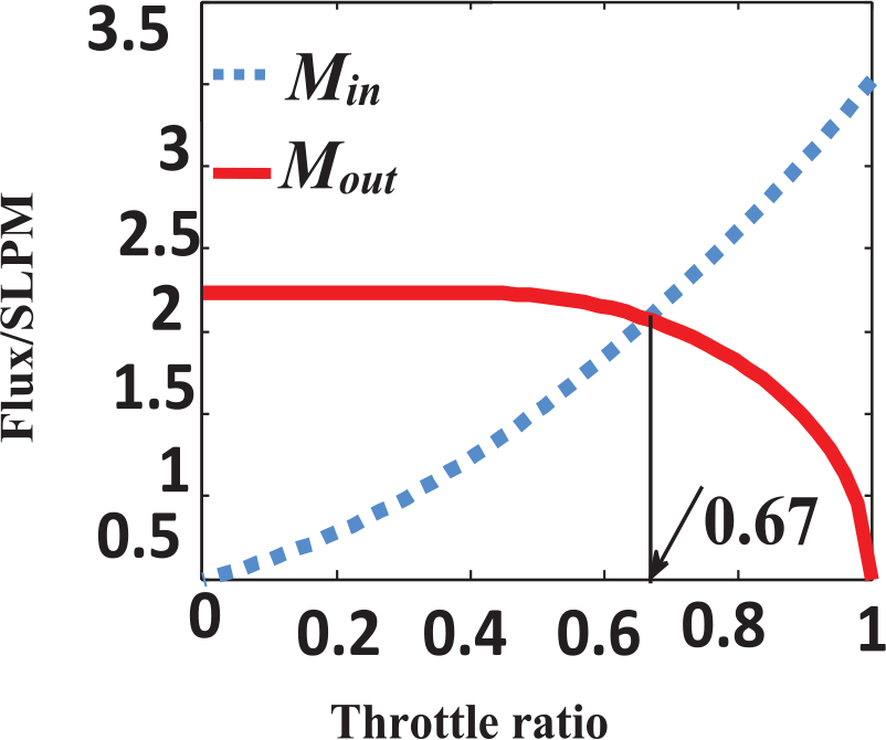
In order to validate the accuracy of this method, the parameters are listed in Table 1. The relationship between Mout and Min and the throttle ratio are shown in Figure 5, in which the throttle ratio is defined as
Parameters used in Figure 5.
Process of solving the flow field pressure distribution.
In Figure 5, the “SLPM” is abbreviated from ‘Standard Liter Per Minute. The value of pd varies from pa to p0, and the throttle ratio varies from 0 to 1. The flux error is minimum when the value of γ is 0.67. Therefore, the boundary condition of cavity is confirmed.
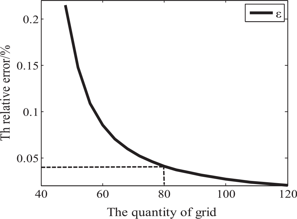
The equal spacing grid is applied on single-orifice bearing. The grid division parameters (Nx = Ny) should be properly set to improve the calculation efficiency and accuracy. The range of the grid division parameters are 16–100, and the bearing parameters used for grid optimization are same as the parameters listed in Table 1.
There is relative error in calculation of static characteristics. The larger Nx = Ny is, the more accurate calculation of static characteristics is. The relative error of the load ability of the bearing is defined as equation (14), and Figure 6 shows the attenuation curve of the relative error for bearing
Relationship between grid parameters and calculation error.
With the consideration of the efficiency, the grid parameter (Nx = Ny) of single-orifice bearing is selected at 80 mm where the relative error is 0.04%. Figure 7 shows that the maximum pressure is present at the cavity and the pressure decreases rapidly from cavity to gas boundary. The unbalanced distribution of pressure indicates that the stiffness stability of the single-orifice aerostatic thrust bearing is not well. The load and stiffness are calculated with the structural parameters listed in Table 2.
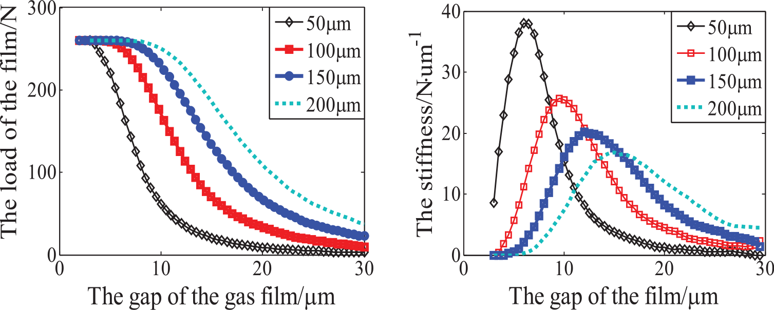
Static characteristics of the guideway with different orifice diameters.
Parameters of slider.
Figure 7 presents the effect of orifice on aerostatic bearing slider. The stiffness of the film can be improved efficiently by decreasing the diameter of orifice, while the corresponding optimum gap of the film decreases accordingly, which raises higher requirement of machining accuracy for bearing.
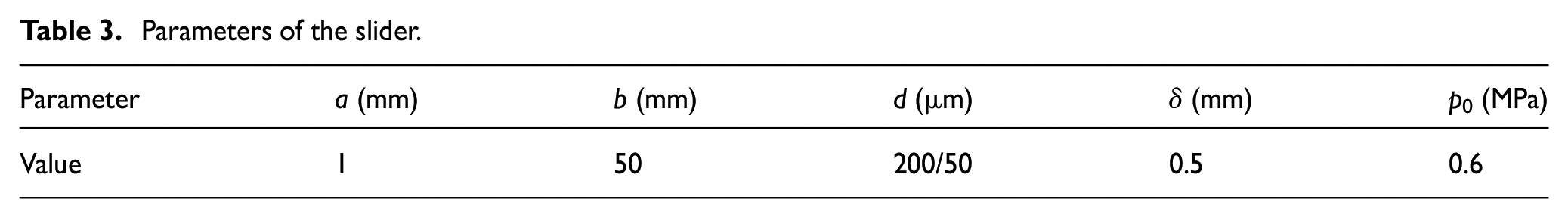
The single-orifice sliders with the orifice diameter at 200 and 50 μm, respectively, are designed to validate the proposed model and solution procedure, and the parameters of the slider are shown in Table 3. Figure 8 shows the experimental setup; the digital pressure sensor HSTL-BLZ200Kg with the measure range at 0–200 kg and the minimum resolution at 0.01 kg is chosen to measure the load of the bearing We; the Mahr is chosen to measure the displacement he. The stiffness of the bearing is given by
Parameters of the slider.
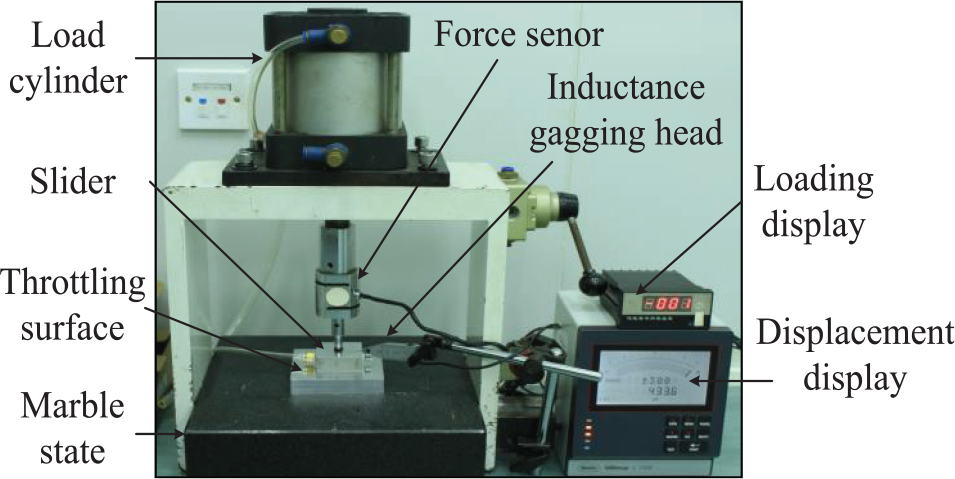
Experimental setup.
The static characteristic experiment of single-orifice is carried out on the developed slider, and Figure 9 shows the theoretical and experimental results. With the diameter of the orifice at 50 μm, the theoretical optimum stiffness and optimum corresponding gap are 30–40 N/μm and 5–8 μm, respectively, and those of the experimental data are 34–48 N/μm and 5–7 μm, respectively. With the diameter of the orifice at 200 μm, the theoretical optimum stiffness and optimum corresponding gap are 12–18 N/μm and 14–17 μm, respectively, and those of the experimental data are 15–24 N/μm and 14–18 μm. The theoretical results have a good agreement with the experimental data, which verifies the accuracy of the proposed model and solution. Besides, the errors between the computation and experiment caused by the unstable and eccentric load are considered during the test.
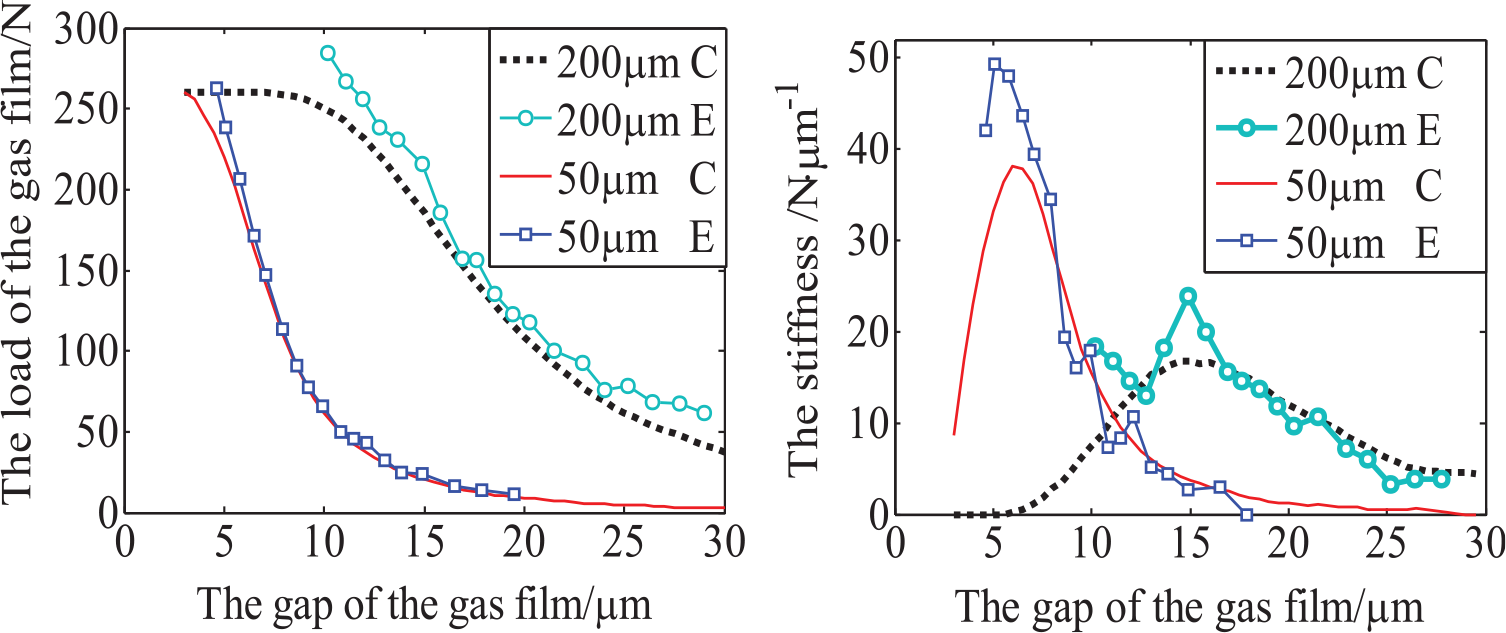
Comparison between the experiment (E) and computation (C).
Application
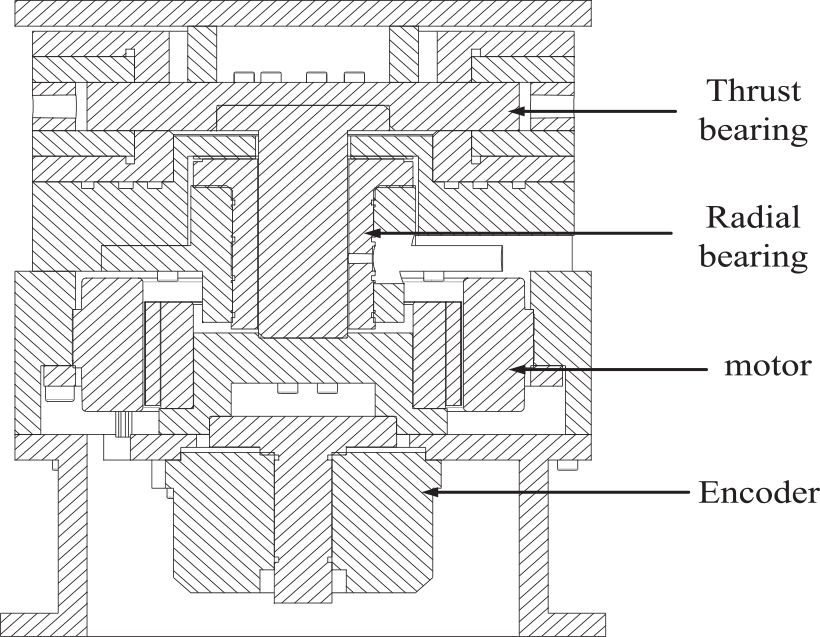
Based on the proposed model and solution, an optimal design on an aerostatic turntable is performed. Aerostatic turntable mainly consists of the thrust and radial bearings. Because the load is supported by the thrust bearing, the accuracy of the turntable is mainly determined by the thrust bearing. The shape of thrust bearing is usually circular ring and the throttling type is usually multi-orifice and gap thrust. The throttling type of radial bearing is usually multi-orifice.
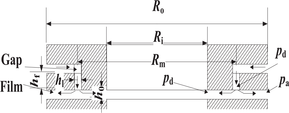
The configuration of the orifices on the thrust bearing is shown in Figure 10. In Figure 10, Ri, Ro and Rm are the inner and outer radii of the bearing and the radius of orifice array, respectively. The Reynolds equation is described in cylindrical coordinates. The boundary condition jointed to atmosphere is Dirichlet and the discrete form is defined by
where Γ a and Γ d are the boundary conditions at the gas exit and cavity, respectively.
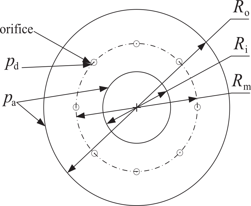
Configuration of the orifices on the thrust bearing.
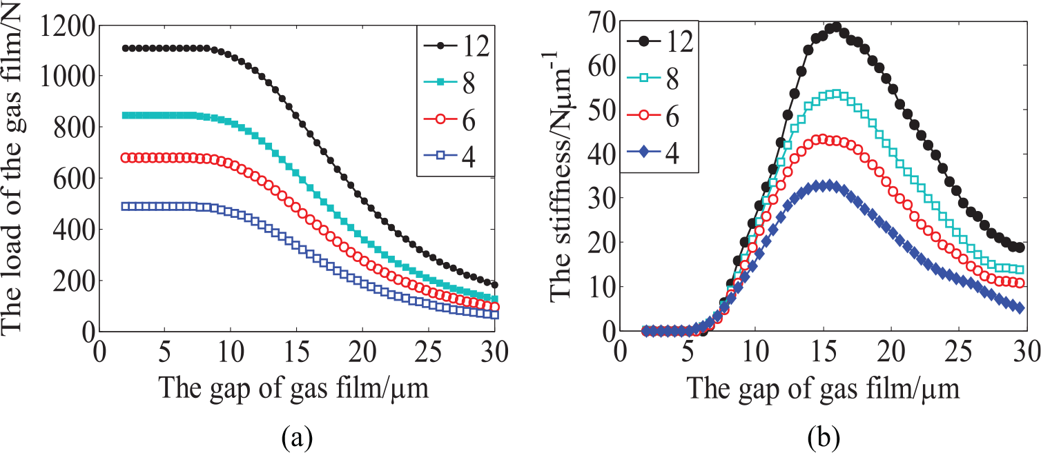
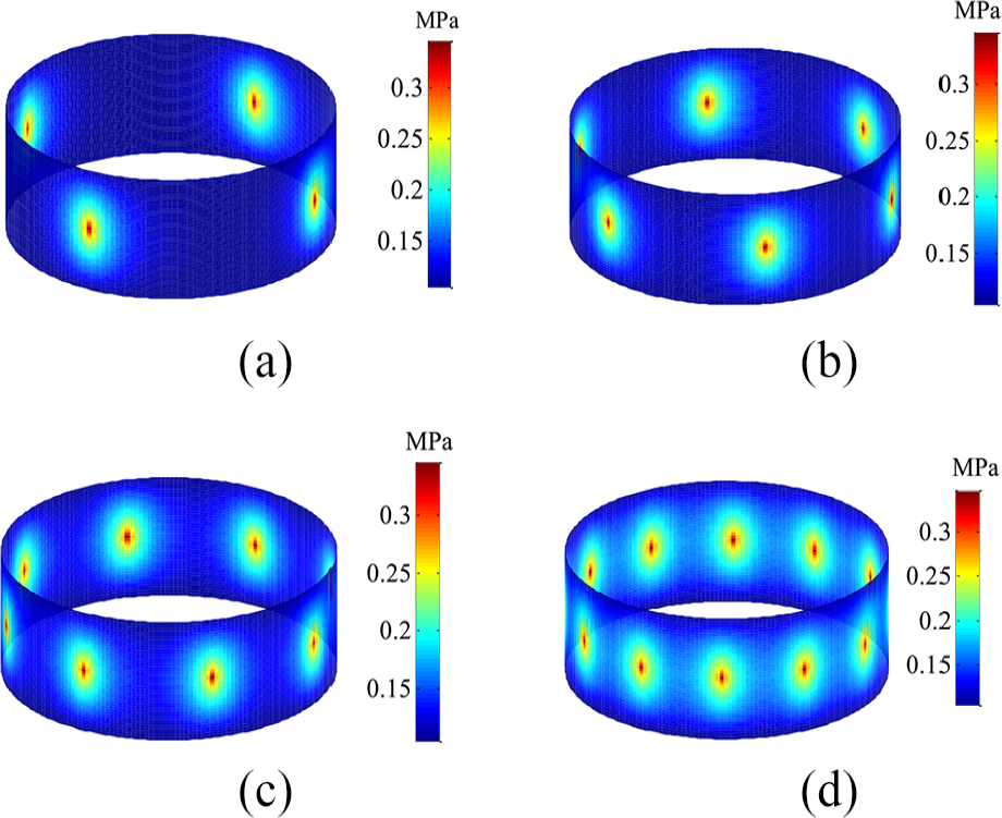
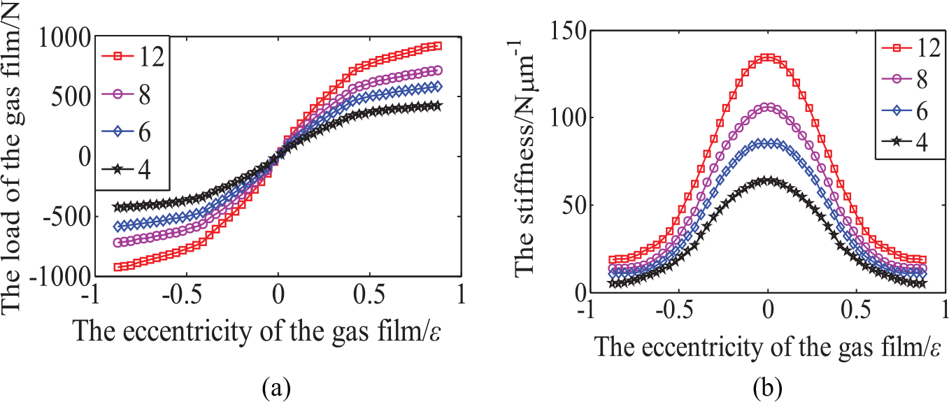
The parameters of the thrust bearing are listed in Table 4 based on the design requirements. In the actual air flow, pd should ensure the values of Min and Mout are equal, so the pressure distribution is obtained by the model solution. Figures 11 and 12 show the pressure distributions and static characteristics of the thrust bearing with different numbers of orifice, respectively, and the load and stiffness of the bearing increase with the number of the orifice.
Parameters of the thrust bearing with orifice.
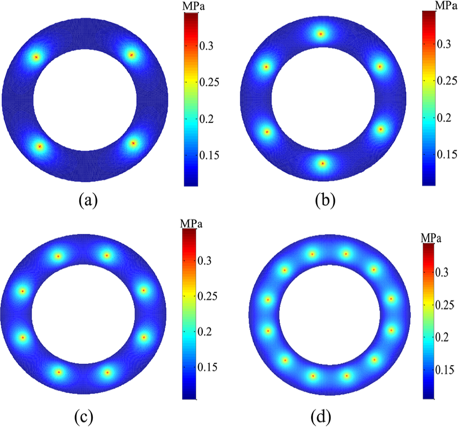
Pressure distributions of the thrust bearing with different numbers of orifice: (a) Nd = 4, (b) Nd = 6, (c) Nd = 8 and (d) Nd = 12.
Static characteristics of the thrust bearing with different numbers of orifice: (a) load and (b) stiffness.
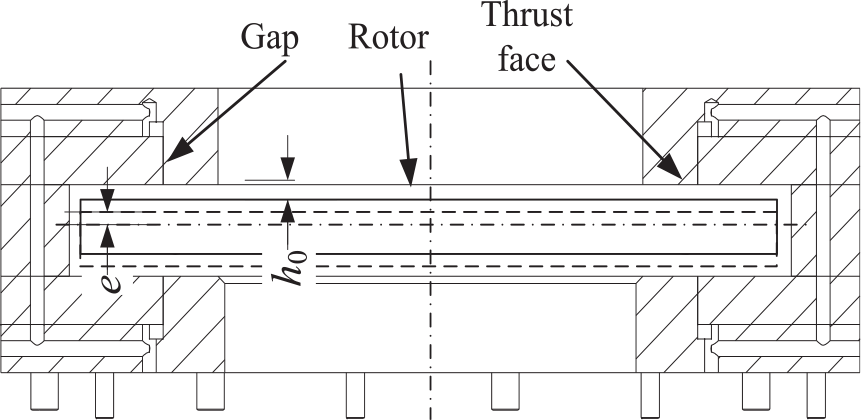
The section of the thrust bearing with gap restriction is shown in Figure 13. In Figure 13, Rm is the radius of the circle gap and
Section of the thrust bearing with gap restriction.
The Reynolds equation of the flow of circle thrust bearing is also described in cylindrical coordinates. The thickness of the uniform gap is h0. The difference scheme of the Dirichlet boundary condition is same as that of the thrust bearing with multi-orifice.
The gas flow in gap can be considered as laminar flow and the flux Min in the gap is obtained by
On the assumption that pd is known, the pressure distribution can be obtained and the discrete format of Mout is
According to equation (17), hf and hl have an influence on Min. Therefore, the quantitative analysis on the static characteristics is performed based on the parameters in Table 5.
Parameters of the thrust bearing with gap.
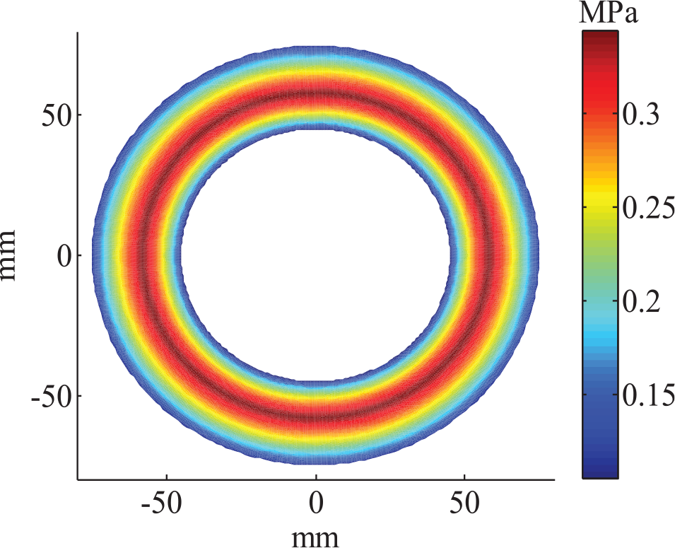
When the values of hf, hl and h0 are 10, 16 and 10 μm, respectively, the pressure distribution of the thrust bearing is shown in Figure 14. In Figure 14, the pressure presents the maximum value at the gap and decreases along the radial direction and is distributed uniformly in circumferential direction. The static characteristics of the bearing are presented in Figures 15 and 16.
Pressure distributions of the thrust bearing with gap.
Static characteristics of the thrust bearing with different hf: (a) load and (b) stiffness.
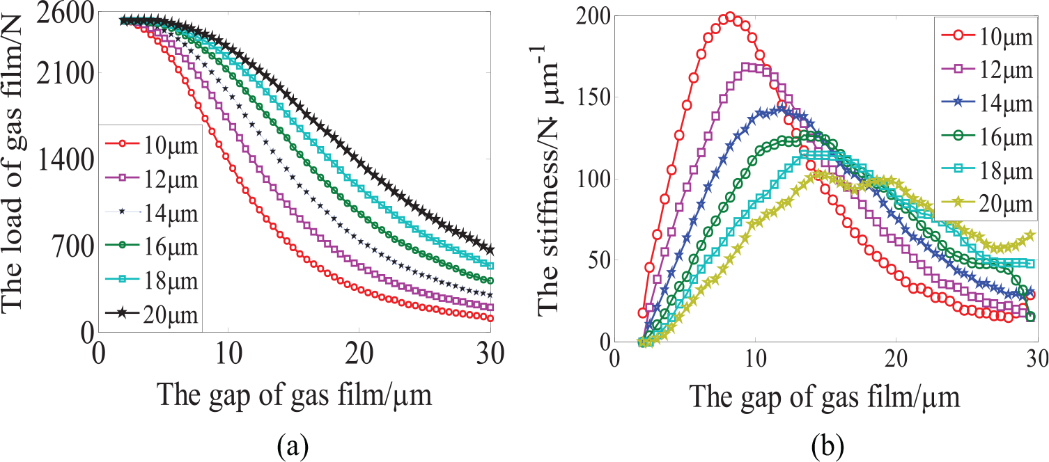
Static characteristics of the thrust bearing with different hl: (a) load and (b) stiffness.
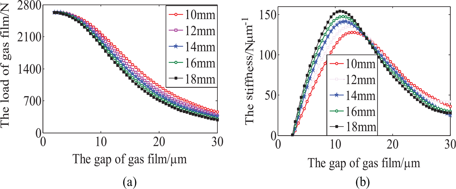
From Figure 15, it can be observed that hf has a great influence on the static characteristics, and the lager the value of hf is, the higher the optimal stiffness will be, and the corresponding optimal h0 decreases slightly.
According to Figure 16, h1 also has great influence on the static characteristics, and the smaller the value of h l is, the higher the optimal stiffness will be, while the corresponding optimal h0 decreases distinctly. Based on the comparison between the results of Figures 12 and 16, it is known that the bearing with gap has a better static characteristics than that with orifice.
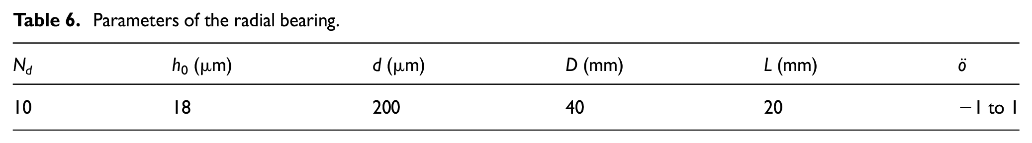
The structure of the radial bearing is shown in Figure 17. D is the diameter of the bearing, L is the width of the bearing, h0 is the uniform thickness of the air film, d is the diameter of the orifice and e is the eccentricity.
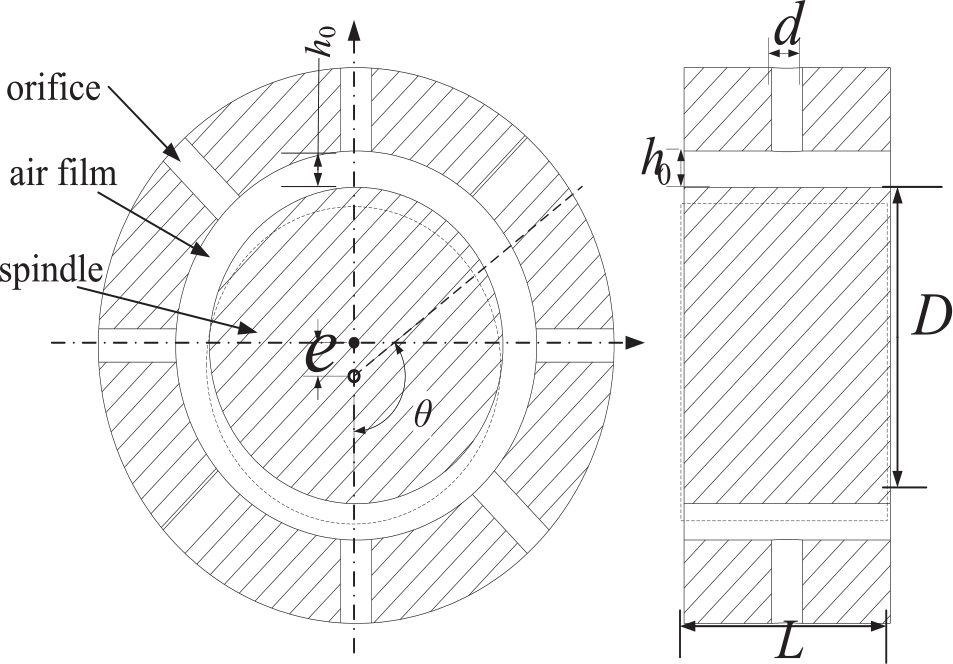
Structure of the radial bearing.
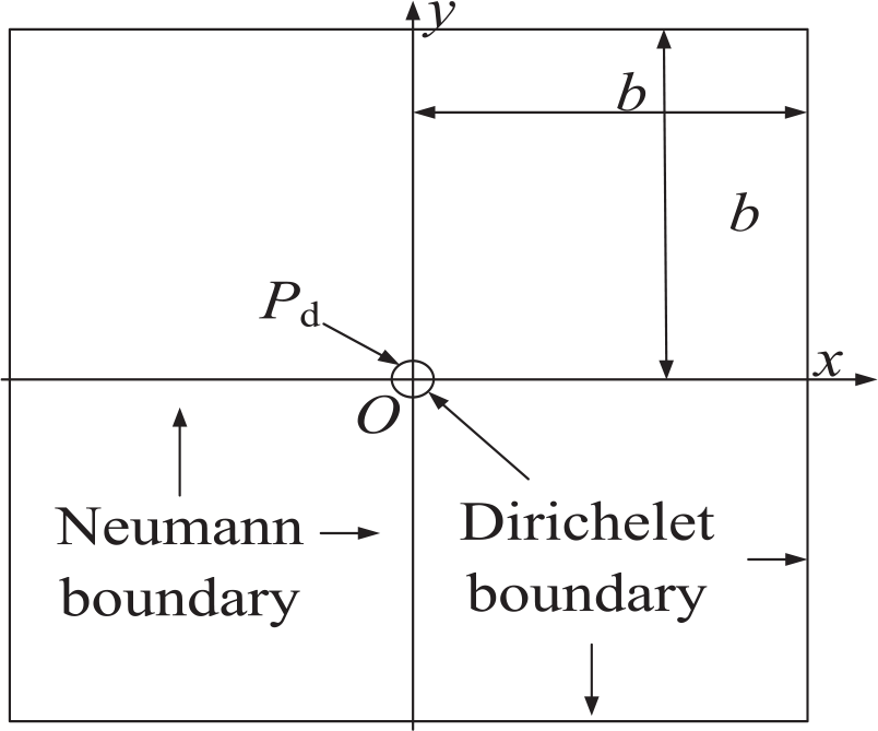
The value of h0 is far less than those of D and L, so the influence of the curvature of air film on the flow is negligible. Therefore, the film model can be expanded to a rectangle model, and its right and left can be supposed to Neumann boundary conditions, whose grids and boundary nodes are shown in Figure 18.
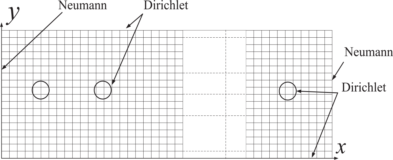
Diagram of the grid partition.
According to Figure 17, the clearance of the air film can be expressed as
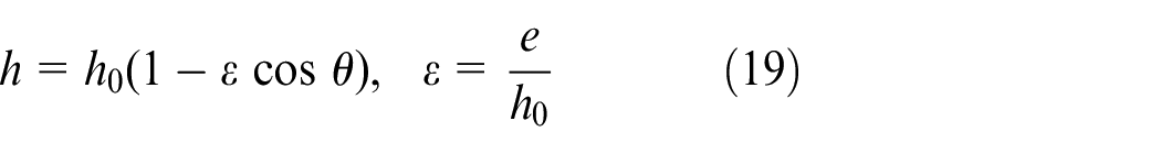
where ε is the eccentricity ratio of the radial bearing.
On the assumption that the pressure of the air cavity at ith orifice is pdi and the flow error is minimum when the pressures of all air cavities are optimal comprehensively, Min and Mout are the functions of pdi and their mathematical relationship is
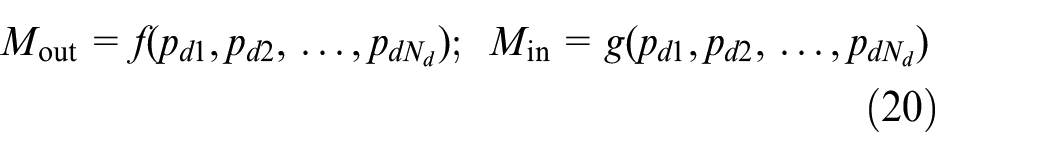
The objective function based on pdi is

Therefore, the solution procedure of the pressure distribution of radial bearing is shown in Figure 19.
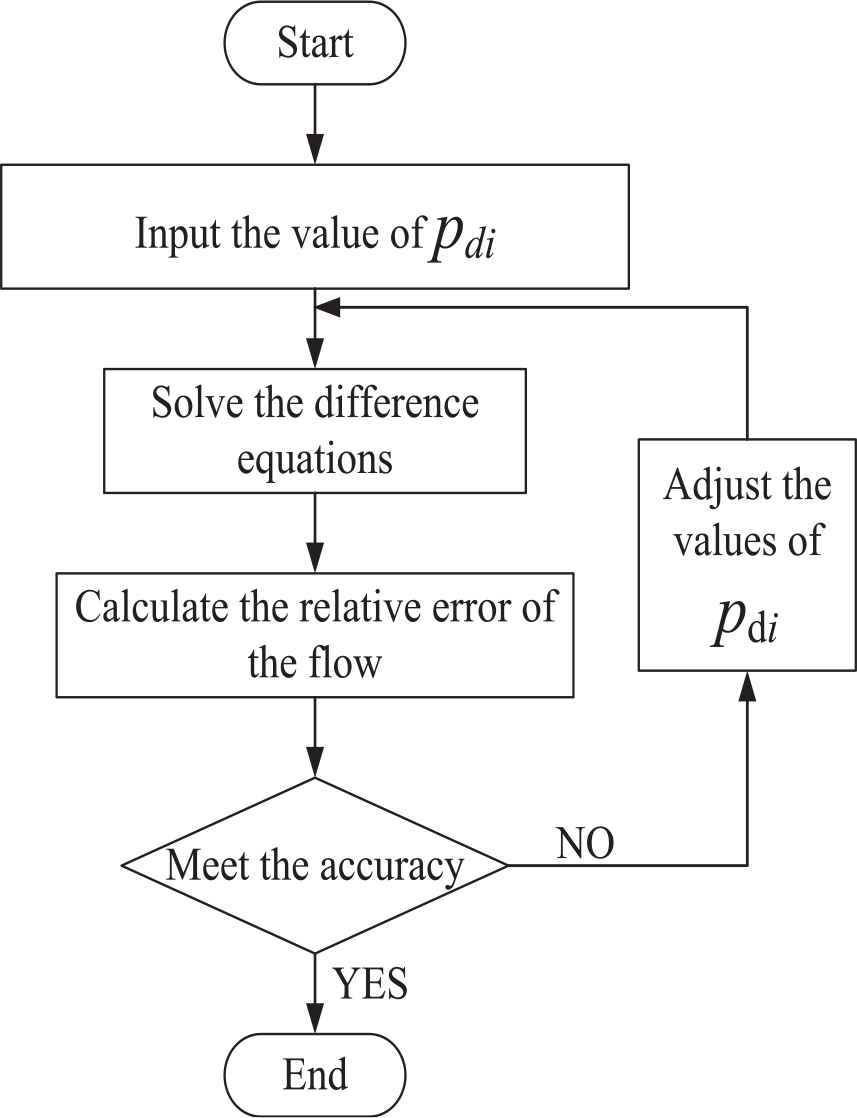
Solution procedure of the pressure distribution of radial bearing.
Suppose that the cavity pressure of each orifice is equal when the radial clearance is uniform and whose value is pd0. Then, the cavity pressure of the orifice with the eccentricity is written as

With the use of the optimal toolbox in MATLAB, the adjust question of pdi can be transformed to a nonlinear optimal question.
The parameters of the radial bearing are presented in Table 6. The pressure distributions of the radial bearing with different numbers of orifices are shown in Figure 20. The more the number of orifice is, the higher and more uniform the pressure distribution of the bearing will be.
Parameters of the radial bearing.
Pressure distribution of the radial bearing.
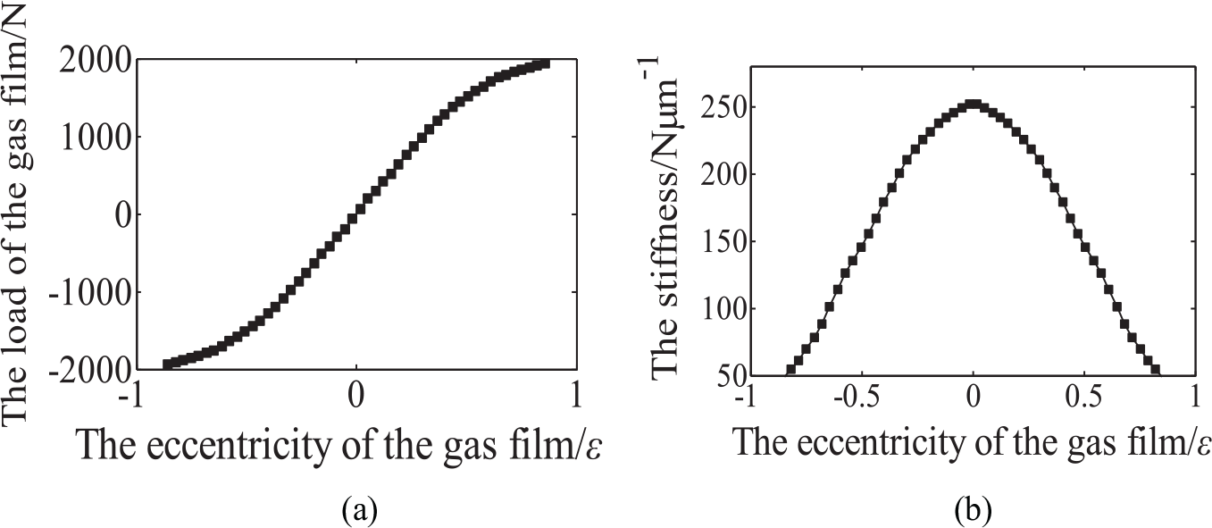
Figure 21 presents the load and stiffness of the radial bearing. The load and stiffness decrease with the value of ε, and the maximum load and stiffness increase with the number of orifice.
The (a) load and (b) stiffness of radial bearing.
Based on the analysis above, the structure of the aerostatic turntable is designed as Figure 22.
Structure of the aerostatic turntable.
According to the results of Figures 11, 12 and 14–16, the thrust bearing adopts the gas restriction, and the values of wf and hf are 16 μm and 10 mm, respectively. The structure of the thrust is shown in Figure 23, where h0 is the uniform thickness of the air film, e is the eccentricity and ε = e/h0.
Structure of the thrust bearing.
Based on the solution of thrust bearing above, the static characteristics of the thrust bearing are obtained and presented in Figure 24. To ensure the load and stiffness of the bearing, the eccentricity e cannot be small enough. According to Figures 15 and 16, the optimal thickness of the air film is 10 μm. With the consideration of the influence of the thickness of the air film on the static characteristics of the bearing, the parallelism of the thrust face should less than 1 μm.
Static characteristics of the designed thrust bearing: (a) load and (b) stiffness.
The load requirement of the radial bearing in aerostatic turntable is lower than that of thrust bearing, and more orifices will increase the manufacturer’s difficulty of the bearing, so the number of Nd is chosen as 6, and other parameters are the same as given in Table 6. The optimal thickness of the air film in radial direction is 18 μm. To avoid the bearing lock, the cylindricity and squareness of the radial bearing are both 1 μm.
The ultra-precision cutting technology is used to ensure the surface precision of the key parts. In the machining process, the wavefront interferometer is used to measure the machining error, which can compensate the machining until the result meets the accuracy requirement. Figure 25 shows the machining spot and result.
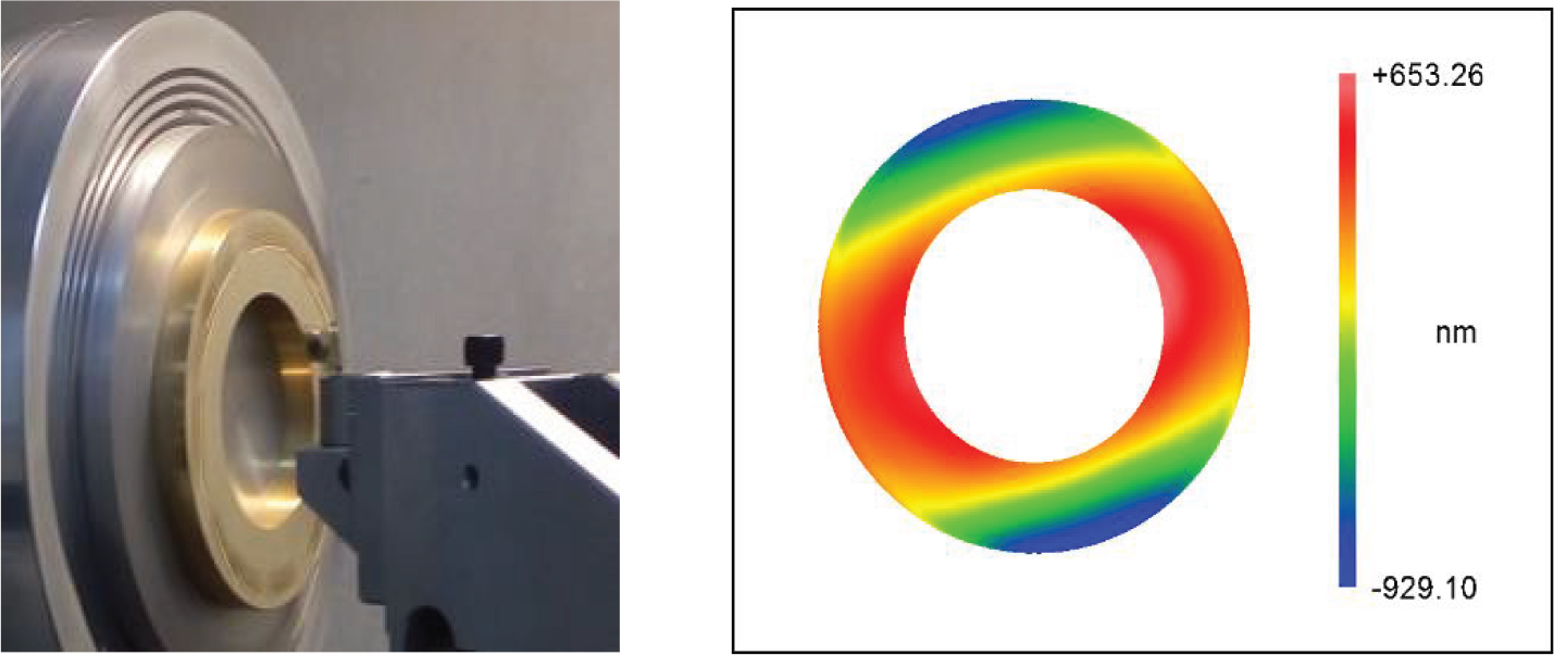
Machining spot and result.
The gap is equipped by the thrust ring and convex plate, and the assembling process is carried out under the microscope. Figure 26 shows the gap width hl at different position, and the values of hl are both about 16 μm, which indicates that the gap is uniform.
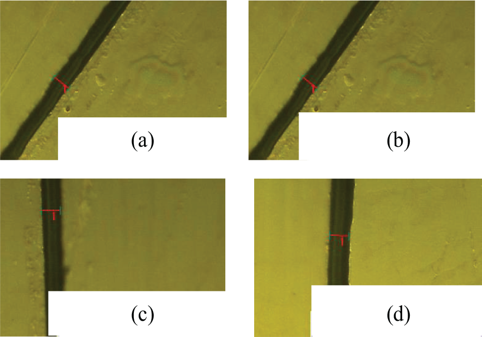
The assembling result of the gap: (a) 15.78 µm, (b) 16.62 µm, (c) 16.40 µm and (d) 16.40 µm.
Accuracy test of the turntable. The LK-G10l laser displacement sensor is fixed at the end face with the radius of 90 mm to test the accuracy of the turntable, and the test data are processed by detrending and averaging. Figure 27 presents the test spot and result. The runout of the end face is about 0.5 μm, which shows the robust of the design and manufacture.
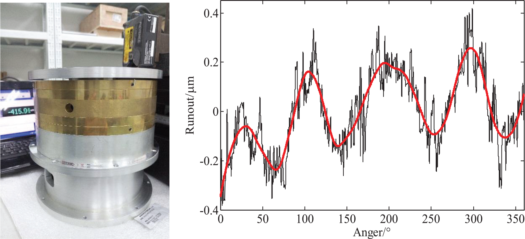
Accuracy test spot and result.
Conclusion
An aerostatic lubrication model based on finite element method with flux error feedback is put forward and validated, and the proposed model is applied to the optimal design of the aerostatic turntable. The conclusions can be drawn as follows:
The good agreement between the mathematical and experimental results of the static characteristics of the aerostatic bearing slider validates the accuracy and robustness of the proposed model.
An optimal design of an aerostatic turntable is performed based on the proposed model and the type, and parameter and configuration of the restriction are obtained by the optimal results.
The ultra-precision cutting technology is applied to the manufacturer of the aerostatic bearing to ensure the performance of the turntable, and the runout of the end face is about 0.5 μm.
Footnotes
Declaration of conflicting interests
The author(s) declared no potential conflicts of interest with respect to the research, authorship and/or publication of this article.
Funding
This work is financially supported by the Science Challenge Project (TZ2018006), Key Research and Development Plan (2016YFB1102304) and National Natural Science Foundation of China (No. 51405151).