
Abstract
Shear thickening fluid is a smart material with rheological properties that can be rapidly varied by excitation changes. To fully explore the advantages of using shear thickening fluid in various devices, a phenomenological model for simulating complex viscosity characteristics of the shear thickening fluid has been developed, and an analytical model has been presented to predict the mechanical characteristics and performance of a damper filled with shear thickening fluid. Based on the analytical model, the force displacement curves are first analyzed for different excitation amplitudes and frequencies. Second, an investigation of the time history of the damping force at various excitation amplitudes is conducted. Finally, the effects of key design parameters on the force displacement and force velocity curves are discussed. The results show that the shear thickening fluid damper exhibits significant velocity correlation, and the damping force increased as the shear rate of shear thickening fluid increased until the threshold value. For the vibration with high frequency, or fast velocity, or large amplitude, the shear thickening fluid is easy to have high shear rate, which results in a great vibration control capability for the shear thickening fluid damper.
Introduction
Passive control is the simplest control method, and a damper is the most commonly used passive control device. However, the weaknesses of the passive control approach, such as inflexibility and poor adaptability, limit its widespread applicability. Therefore, the interests in dampers that consist of adaptive materials have increased for better vibration control.
Typical adaptive materials include electro-rheological (ER) fluid and magneto-rheological (MR) fluid. Their dynamic properties may be modified when subjected to external electric and magnetic fields. Owing to their rheological properties, ER fluids and MR fluid can be used not only in dampers1–5 but also in other applications, as indicated by previous studies.6–8 Another example of an adaptive material is a laminate containing a pre-deformed wire made of shape memory alloy (SMA)9,10 that modifies the properties of a smart material as its temperature varies. However, all these materials require an external power source to be activated, which increases a device’s weight and complexity. In order to mitigate structure or equipment vibrations without an external power source, a material that changes its own properties according to the external excitation conditions may be used as an alternative to conventional materials.
A novel smart material, named shear thickening fluid (STF), has been introduced for energy dissipation.11–15 An STF is a highly concentrated colloidal suspension that consists of monodisperse nanoparticles suspended in a carrying fluid; it is capable of both flowable and rigid behaviors when subjected to sudden stimuli. In other words, the STF’s mechanical properties (shear modulus, damping factor, etc.) can be changed by stimuli (as seen in Figure 1). Moreover, according to Waitukaitis and Jaeger’s 11 research, the energy absorption and deformation of STF are reversible. Because of these benefits, STFs have great potential for intelligent control in some engineering fields.
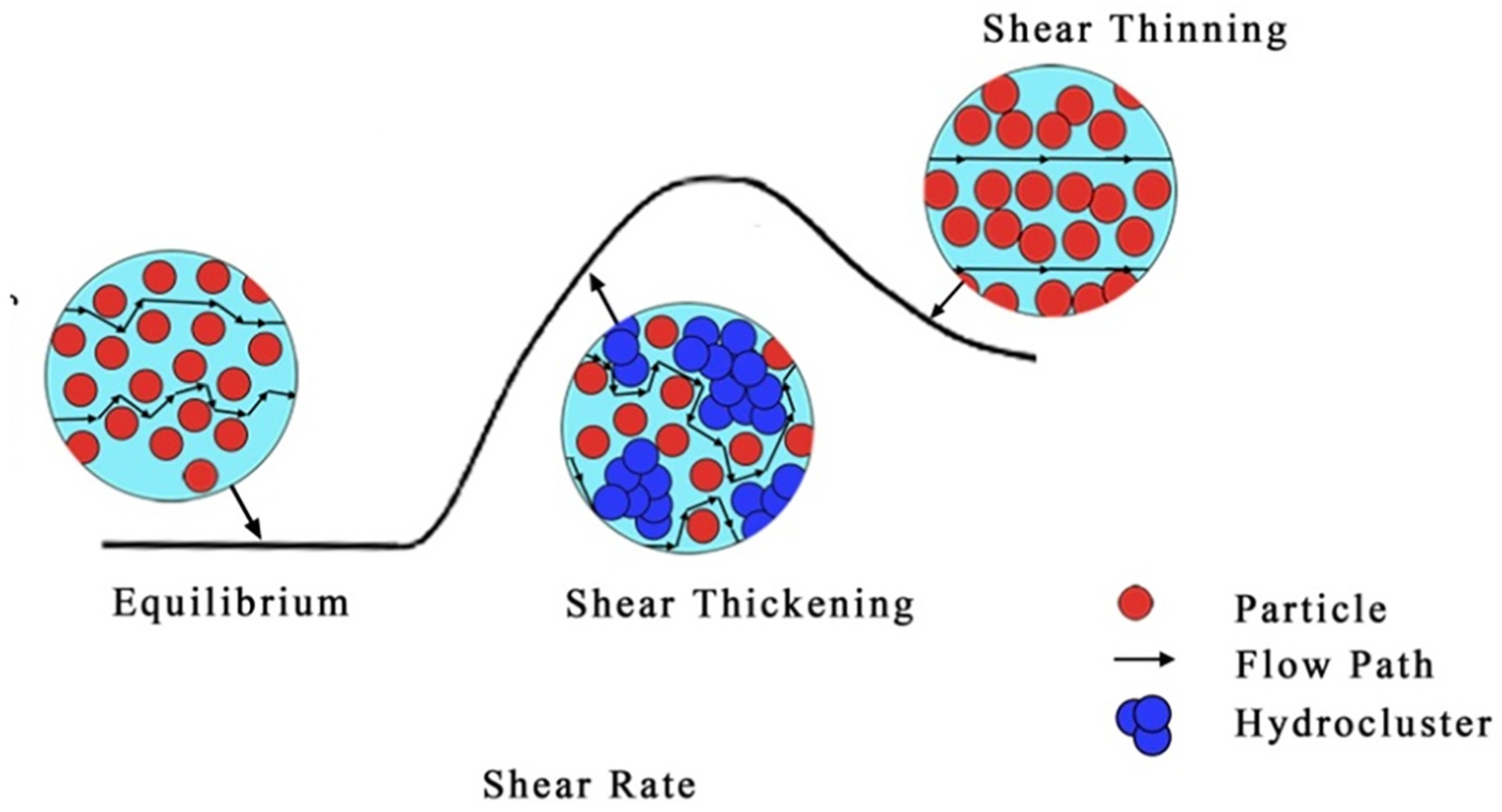
Schematic of shear thickening fluid.
Considering earthquake resistance as an example, the performance of an STF-filled damper was tested under different ground acceleration conditions by Yeh and colleagues16,17 and was found to exhibit a high damping force at a peak ground acceleration of 500 gal, although the STF damper exhibited a low damping force at a peak ground acceleration of 100 gal. This indicates that excitation loads found in civil engineering, such as those near fault or great earthquakes that often feature large energy loads and fast-acting velocities, can provide the exact conditions required by an STF to initiate shear thickening behavior. However, to the authors’ best knowledge, STFs are still rarely applied in civil engineering. This study conducted a theoretical investigation on the mechanical performance and characteristics of a damper filled with STFs, and aimed to illustrate the feasibility of STF dampers in vibration control in civil engineering applications.
This paper is organized as follows. Section “Phenomenological model for STF materials” presents the phenomenological model used to simulate the complex viscosity characteristics of the STF material. Based on flow momentum equations, an analytical model of an STF damper using a parallel plate model is established in section “Analytical model for an STF damper.” Section “Results and discussion” investigates the mechanical properties and characteristics of the STF damper under sinusoidal excitation for cases with different excitation amplitudes and excitation frequencies so as to further elucidate the nonlinear behavior of dampers. Moreover, the effect of the annular gap between the cylinder and the piston on the force velocity curves is discussed so as to better design it. Concluding remarks are presented in section “Conclusion.”
Phenomenological model for STF materials
The shear rate–dependent properties of the STF considered in this study have been reported by many researchers,18,19 using various approaches;20,21 however, in this work, the piecewise model was replaced by a phenomenological model that possesses equivalent viscosity characteristics. This model was chosen to describe the continuum properties of the STF material and to further show the integrity of the mechanical properties of the STF damper.
To simulate the viscosity characteristics of the STF materials with an increasing shear rate, the following continuum function was used
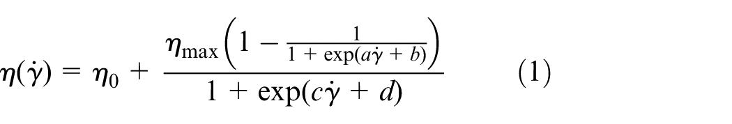
where a, b, c, d, η0, and ηmax are the parameters obtained from the experiments with STF materials, and
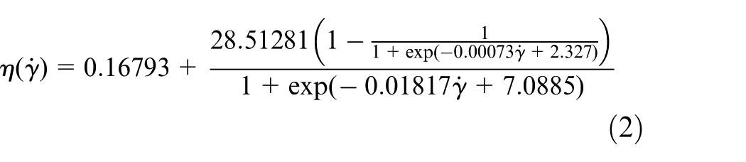
Our goal was to demonstrate the effectiveness of the phenomenological model defined by Equation (1) for different experimental viscosity curves corresponding to different materials that exhibit shear thickening rheology. Thus, the mechanisms behind the shear thickening behavior are not discussed. Various publications have already reported that several suspensions of fumed silica in different polypropylene glycol solutions present shear thickening behavior.17,22,23 For example, according to Zhang et al., 23 the viscoelastic behavior of an STF sample against the dynamic shear rate can be plotted as in Figure 2. In their experiment, the STF had a primary particle size of 14 nm and a surface area of approximately 200 m2 g−1, and its rheology under dynamic loading conditions was measured by a parallel plate rheometer (MCR 301, Anton Paar Companies, Germany). The diameter of the parallel plate was 20 mm, and the thickness was set to 0.2 mm. From Figure 2, it can be seen that the phenomenological model based on Equation (2) agrees well with the data from that experiment. The drastic increasing behavior (shear thickening) at the critical shear rate is accurately described, and the decreasing behavior as the shear rate exceeds a certain value is also exhibited
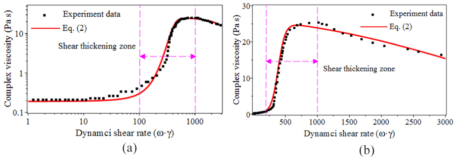
Phenomenological model for the complex viscosity of the STF: 23 (a) double logarithm coordinates and (b) linear coordinate.
where
Analytical model for an STF damper
A schematic of the STF damper is shown in Figure 3. The effective fluid annular gap comprised the entire annular space between the piston’s outside diameter and the inside of the damper cylinder’s housing. Thus, the STF was pushed through the annular gap when the piston moved forward or backward. The overall length and effective axial pole length of the damper are denoted by L and l, respectively. The outside and inside diameters of the piston are denoted by D1 and d, respectively. Considering the gap denoted by h, the inside diameter of the damper cylinder’s housing can be written as D2 = D1 + 2h. For the theoretical analysis of the STF damper, a few assumptions were made: (1) the fluid flow is continuous, incompressible, and fully developed; (2) the fluid properties are homogeneous within the interval L of the fluid action section; (3) the fluid is in the laminar flow state; and (4) the ratio between the annular gap and the outside diameter of the piston is very small, so the fluid flow can be approximated by the flow between the parallel plates.

Schematic of the STF damper.
Based on the above assumptions, the stress and velocity profiles through the parallel plate model could be described as shown in Figure 4. The width of the parallel plate model could be expressed as the mean circumference of the damper’s annular flow path, namely, b = π (D1 + D2)/2.
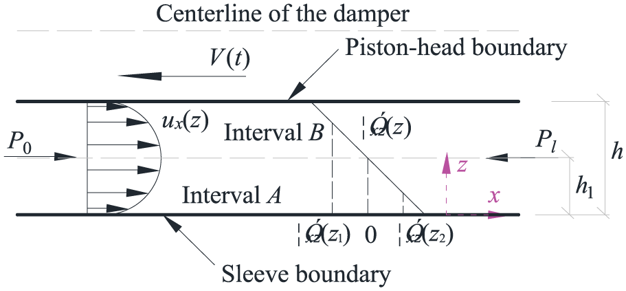
Stress and velocity profiles through a parallel plate model.
The governing equation of the STF flow was obtained using the flow momentum equation as follows
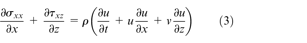
where u and v are the flow velocity of the STF in the directions of x and z, respectively; ∂σxx/∂x and ∂τxz/∂z are the pressure gradients in the x and z direction, respectively; ∂u/∂t is the inertia of the STF; and ρ is the density of fluid.
Based on assumption (3), fluid motion in the x direction was considered as one-dimensional flow, and it did not flow in the z direction. Therefore
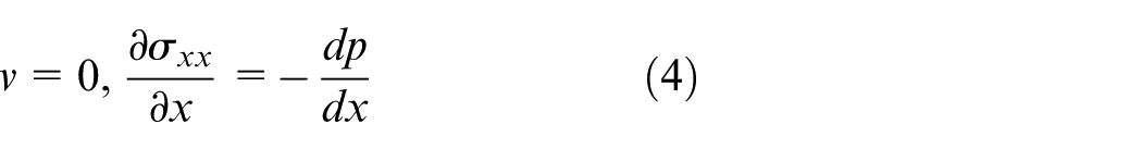
where dp/dx is the pressure gradient.
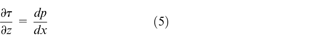
As the quasi-static model was employed in this study, the inertial effect of the fluid could be ignored (∂u/∂t = 0). Moreover, according to assumptions (1)–(3), the shear stresses lie along the x direction for τxz = τ. Therefore, the control equations could be simplified to
and the solution could be written as
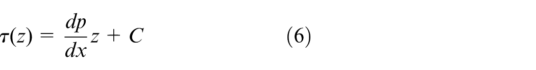
where C denotes a constant, which can be determined based on the boundary conditions.
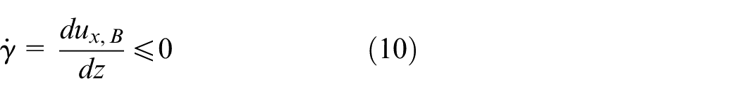
As seen in Figure 4, the shear rate had the following expression in interval A
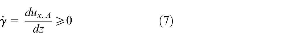
Thus, the shear stress could be written as
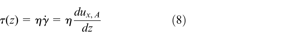
where η denotes the viscosity of the fluid.
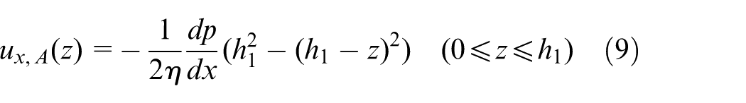
By substituting Equation (8) into Equation (6), integrating once about z, and then considering the boundary condition of ux, A (0) = 0 and τ(h1) = 0, the flow velocity of the STF in the x direction could be obtained as
In interval B, the shear rate had the following expression
and the corresponding shear stress could be written as
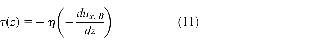
Using methods similar to those used to obtain Equation (9), and considering the boundary condition ux, B (h) = V(t) and τ(h1) = 0, the flow velocity of the STF in the x-direction could be given as
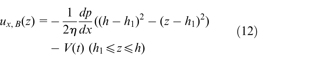
where V(t) is the velocity of the parallel plate mode.
Considering that the volume flow rate Q had the following form
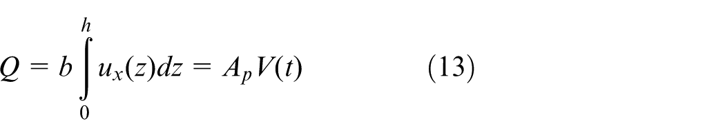
and substituting Equations (9) and (12) into Equation (13), as well as considering h1 = h/2, the relationship between the piston velocity and the damping force, F(t), could be obtained as follows
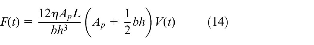
in which h is the gap of the parallel plate mode, and Ap is the area of the piston action.
For the power law fluid, the relationship of the shear rate and velocity in the parallel plate mode could be written as
By substituting the phenomenological model from Equation (1) into Equation (14) and combining it with Equation (15), the relationship between the damping force and the piston velocity could be obtained
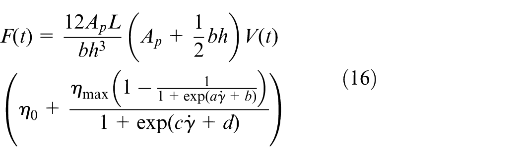
Equation (16) shows that the damping force of the STF damper was a linear function of the effective axial pole length, but was a nonlinear function of the annular gap and the piston velocity. This indicates that the latter two parameters have a significant effect on the damping force of the STF. This is especially true for the annular gap parameters. Therefore, we will only discuss the effects of the damper’s annular gap on its mechanical behavior.
Assuming that the sinusoidal excitation on the piston rod had the following form

the velocity could be written as

where W and ω are the excitation amplitude and frequency, respectively. Therefore, by substituting Equation (18) into Equation (16), the force displacement of STF damper could be obtained.
Results and discussion
Mechanical performance of the STF damper
This investigation of the mechanical performance of an STF damper will base the properties of the STF material on Zhang et al., 23 which has a primary particle size of 14 nm and a surface area of approximately 200 m2 g−1. The physical parameters of the STF damper are set as follows: D1 = 0.06 m, D2 = 0.063 m, d = 0.022 m, and l = 0.04 m. These are consistent with the parameters of an MR fluid damper. 24
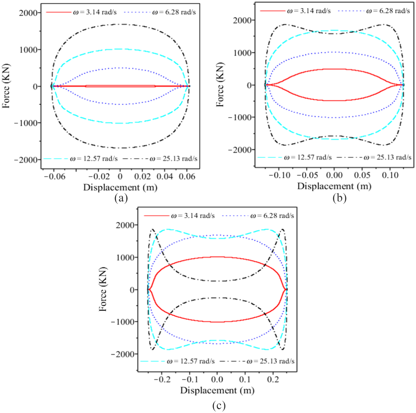
The force displacement performance of the STF damper at various excitation frequencies and amplitudes when h = 1.5 mm were investigated, and the results are shown in Figure 5. From Figure 5, it can be seen that the force displacement curves were almost a straight line when the excitation frequencies were small (e.g. ω = 3.14 rad/s), which indicates that the STF damper had a weak energy-dissipation ability. However, the force displacement curve started to expand when the excitation frequency exceeded a certain threshold, and the curve became more rounded with increasing excitation frequency (e.g. ω = 12.57 rad/s and ω = 25.13 rad/s). As the excitation frequency increased from 6.28 to 12.57 rad/s, the force displacement curve showed significantly nonlinear behavior. The maximum force was approximately 115.83 kN, 17.5 times that of the maximum force (approximately 6.62 kN) at ω = 6.28 rad/s. This was because the STF exhibited shear thickening behavior owing to hydrodynamic clustering effects. Further increasing the excitation frequency to ω = 25.13 rad/s, the maximum damping force was approximately 255.14 kN, only twice that of the maximum damping force at ω = 12.57 rad/s, which indicates that the damping force of the STF started to exhibit linear behavior when the shear thickening mechanism of STF was complete. However, for that case, an increase in frequency could effectively improve the mechanical performance of the STF damper at both ends.
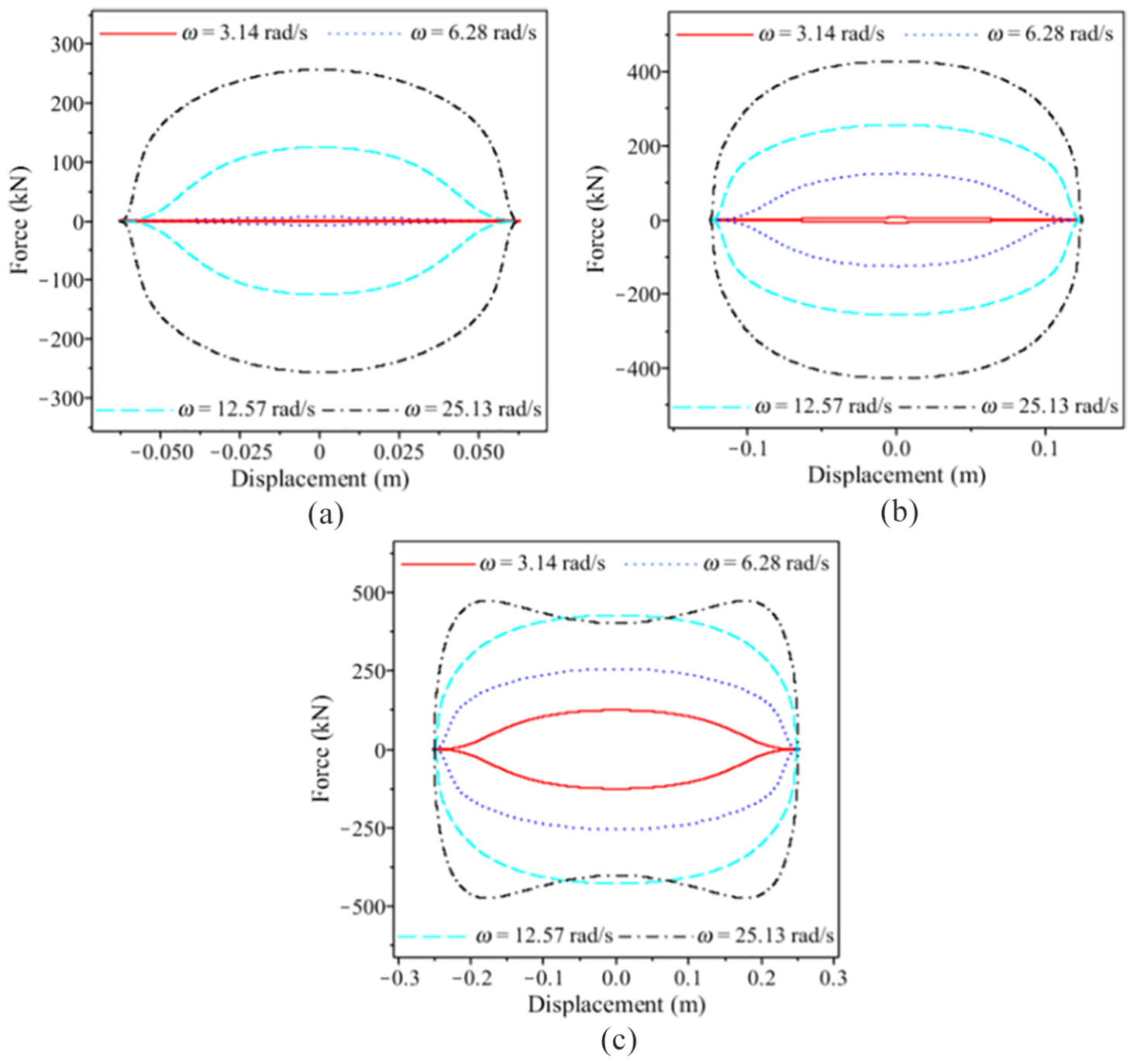
Force displacement performance of the STF damper when the annular gap is h = 1.5 mm: (a) W = 0.0626 m, (b) W = 0.1253 m, and (c) W = 0.2506 m.
Figure 5(a) and (b) shows that, at the same excitation frequency, the force displacement curves had a rounder shape when the excitation amplitude increased to 0.1253 m. As shown in Figure 5(c), when the excitation amplitude increased to 0.2506 m, the force displacement curve exhibited shear thickening behavior under the four excitation frequencies, which induced a larger damping force (e.g. 125.13 kN) for ω = 3.14 rad/s. A further observation of the curve corresponding to ω = 25.13 rad/s indicates that the damping force decreased and had a lower value around the zero displacement than the case with ω = 12.57 rad/s. Moreover, the maximum damping force was approximately 471.06 kN at a displacement of ±0.021 m, rather than at the center. The slope angle was close to 90° at the left endpoint, which indicates that the damping force reached the limiting value of the STF. From these phenomena, we can conclude that STF dampers are very suitable for controlling high-frequency vibrations of structures.
Figure 6 shows the force time performance of the STF damper at different excitation amplitudes when the annular gap was 1.5 mm. As seen in Figure 6(a) and (b), the force time curves showed a similar cosine feature along the entire time axis under sinusoidal excitation, and the maximum damping force increased as the excitation amplitudes increased. However, when the excitation amplitude increased to W = 0.2506 m, the damping force began to decrease after reaching a peak. This phenomenon is consistent with the results shown in Figure 5(c). Moreover, referring to Figure 6(c), the damping force was very small within a certain range. It can be seen that the range was located at the two ends of the STF damper, which may have been induced by the decrease in the vibration velocity of the STF damper at the ends. Further analysis of Figure 6(c) reveals that the range became smaller as the excitation amplitude increased, which indicate the STF damper have better potential in vibration control for structures or equipment with larger vibration amplitudes.
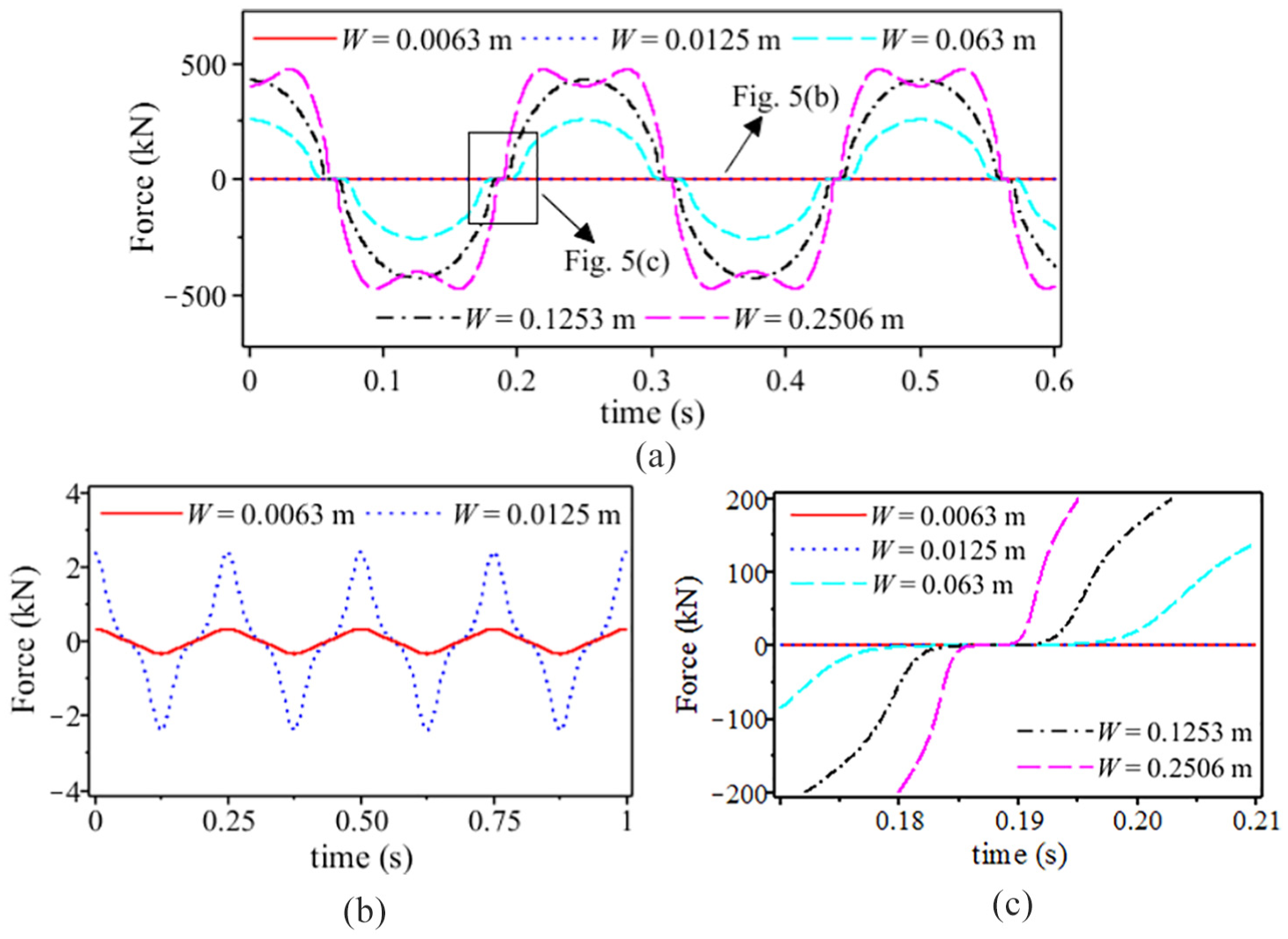
Force time performance of the STF damper when the annular gap is h = 1.5 mm: (a) ω = 25.12 rad/s, (b) local of Figure 5(a), and (c) detail characteristics of the force time curves at the end of the STF damper.
Effect of the annular gap
The maximum damping force of the STF damper would be further improved by decreasing the annular gap, if the machining precision requirements could be met. Figure 7 shows the force displacement performance of the STF damper at various excitation frequencies and different excitation amplitudes when h = 0.75 mm (D2 = 0.0615 m). The maximum damping forces were 1673.2, 1873.2, and 1873.2 kN for ω = 25.13 rad/s at excitation amplitudes of W = 0.0626 m, W = 0.1253 m, and W = 0.2506 m, respectively. These values were much larger than those shown in Figure 5. However, at the excitation amplitude W = 0.2506 m, the shrinking behavior became more obvious as the excitation frequency increased. For ω = 25.13 rad/s, the lowest damping force was approximately 276.20 kN, equal to roughly 15.12% of the maximum damping force, and the slope was very large. The phenomena indicate that the damping force of the STF damper decreased quickly when the excitation load exceeded the extreme limits of the STF.
Force displacement performance of the STF damper when the annular gap is h = 0.75 mm: (a) W = 0.0626 m, (b) W = 0.1253 m, and (c) W = 0.2506 m.
Figure 8 shows the force velocity performance of the STF damper along the direction with increasing velocity. As shown in Figure 8(a), each force velocity curve has two key points (a peak point was absent for h = 3.0 mm because the critical values were larger than the maximum coordinates of the velocity): the first point was the jump point, and the second point was the peak point. Between the velocities corresponding to the jump point and the peak point, the rate of the damping force increased nonlinearly with a decreasing annular gap, and the maximum force increased nonlinearly as well. Referring to Figure 8(b), the jump point moved backward along the velocity axis when the annular gap increased. These behaviors demonstrate that to obtain a large damping force when the velocity is small, the annular gap should be designed to be small. However, after reaching the peak point, the damping force of the STF damper started to decrease with increasing velocity, and the decreasing rate of the damping force increased nonlinearly with a decreasing annular gap. This phenomenon requires attention because once the excitation loads exceed the ultimate load that the STF can handle, the damping force of the STF damper can be decreased rapidly by decreasing the annular gap.
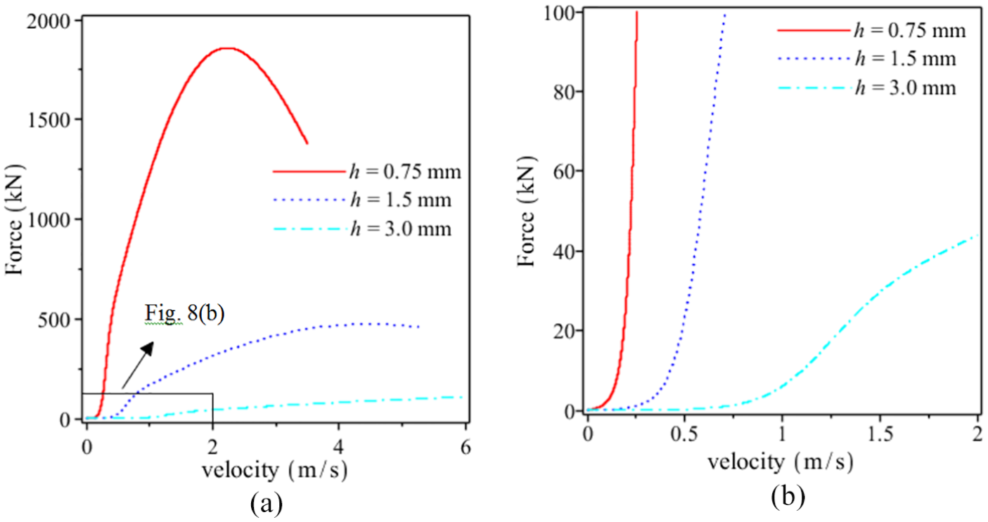
Force velocity performance of the STF damper for the different annular gaps: (a) W = 0.0626 m and (b) W = 0.1253 m.
Conclusion
A phenomenological model for simulating the nonlinear jump increasing and decreasing behavior of an STF material was presented. The presented model was found to accurately predict the complex viscosity curves when the shear rate changes. The curves calculated by the phenomenological model in this investigation then served as input for the analytical model of the STF damper, which was established in conjunction with flow momentum equations, in order to evaluate its mechanical performance and characteristics when subjected to a harmonic load.
The results show that as the excitation amplitude (or frequency) increases, the force displacement curve of the STF damper becomes fuller, and the maximum damping force significantly increases. However, unlike the MR fluid damper, with increased excitation, the force displacement curve of the STF damper did not maintain a steady shape. When the excitation amplitude (or frequency) was very large, the damping force of the STF damper started to decrease after the shear rate exceeded a critical value. Moreover, the extent of the decrease became increasingly intense as the annular gap decreased. Thus, as the annular gap is a key parameter for the design of an STF damper, more attention to the relationship between these excitation conditions and the annular gap is necessary for applications of the STF damper in engineering fields with high frequency, large amplitude, and high-velocity excitations.
Footnotes
Declaration of conflicting interests
The author(s) declared no potential conflicts of interest with respect to the research, authorship, and/or publication of this article.
Funding
The authors acknowledge financial support from National Natural Science Foundation of China (Grant Nos 51608335 and 51608153), China Postdoctoral Science Foundation (Grant No. 2016M591432), and the Shenzhen Knowledge Innovation Program (Grant Nos JCYJ20170413105418298 and JCYJ20170811153857358).