
Abstract
Background:
Indirect measurements of flow rate serve to determine air consumption, leakage values and characteristics of compressed air systems (CASs).
Method:
A new method of indirect flow rate measurement in a pneumatic pipeline system was developed. The method enables to measure the controlled leakage in a branch line and was used to construct automatic measuring systems auditing the compressed air systems piping.
Results:
First, the leak-testing instrument LT-I 200 was designed, constructed, and tested as portable measurement device for the estimation of air leakage flow rate in pneumatic pipeline system. Next, based on the authors’ patent, the automatic measuring system for the measurement of the leakage flow rate in industrial compressed air piping was developed.
Conclusion:
The measurement device was used to estimate of the leakage flow rate and cost of the energy losses in the compressed air piping system.
Introduction
The purpose of the pneumatic piping systems is to deliver compressed air energy (CAE) to the end-use points. 1 The compressed air needs to be delivered with enough volume, appropriate quality, and pressure to properly power the pneumatic components. But after usage, compressed air is released directly into the atmosphere. A typical industrial pneumatic system – compressed air system (CAS) – consists of three main parts: compressed air production plant, pipeline system, and pneumatics equipment (air actuators, air devices, and air tools). Many factories have equipped their production lines with compressed air supplies. Compressed air is present in almost all industries; companies use compressed air for many purposes such as from running huge equipment to powering simple air tools. Pneumatic systems are widely used, especially in the industrial sectors for the drive and control of automatic machines, automatic production lines, and so on.2–4 Compressed air is one of the most expensive sources of energy in an industrial plant because 75% of the total production costs of compressed air are spent on electric energy. Production of compressed air consumes 10% of the total consumption of electric energy in the industrial sector in European Union.5,6A poorly designed pneumatic system can increase energy costs, promote equipment failure, reduce production efficiencies, and increase maintenance requirements. There are many examples of the wastages of compressed air in industry. 7 The main causes of energy waste are leaks, pressure drops, over-pressurization, misuse of compressed air, and poor management of pneumatic system. While designing energy-saving CASs, various methods are applied to reduce energy losses and minimize energy consumption. 8 The pneumatic pipeline systems require a complex approach towards rational energy consumption by effective production, distribution, and application of the compressed air. There are three important reasons why investing time and effort in reducing compressed air costs is worthwhile: it will save energy and money by identifying and eliminating waste; it will improve the reliability and efficiency of the CAS; and it will reduce environmental impact by reduced electricity consumption and consequent lower carbon dioxide (CO2) emissions.
In general, most losses in the pneumatic pipeline systems can be classified into three main groups: losses arising from leakage, artificial demand, and inadequate use. 9 Leakage is one of the largest sources of energy losses in pneumatic pipeline systems, and its removal for the purpose of minimizing and improving energy efficiency of compressed air is both simplest and cheapest. Many companies search for the ways to make energy savings in their production process. Up to 60% of energy costs can be saved through optimisation of both use and losses of compressed air in pneumatic systems. In most cases, this can be achieved by reducing leaks in the pneumatic piping systems. As Benjamin Franklin said, ‘An ounce of prevention is worth a pound of cure’. Therefore, it is worthwhile to look actively for leaks in the pneumatic piping system. 10 Leaks not only waste energy but cause pressure drops, which adversely affect the operation of air-using equipment and tools, thereby reducing production efficiency. Leaks are responsible for considerable waste, frequently up to 40%–50% of energy consumption. The diagram of compressed air pipeline systems with potential leakage points is shown in Figure 1.
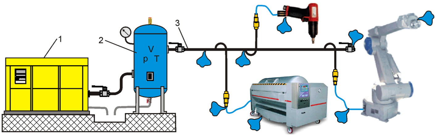
Diagram of compressed air systems.
Leakage can occur at a number of points of pneumatic pipeline system, such as branch line connection, rubber hose, automatic drain trap, quick coupler, air treatment unit, filter, control valve, filter, pressure regulator, and pneumatic actuators.
The following guidelines can help reduce compressed air leakage:
Reduce the air pressure to the minimum acceptable value.
Select good-quality pipe fittings.
Provide welded joints instead of threaded joints.
Provide ball valves for the isolation of unused branch lines and all end-use points.
Pipelines should be overhead, to be inspected easily.
The authors have proposed a new approach to the compressed air leakage measurement methods based on the measurement of the flow through a controlled valve in a branch line of pneumatic pipeline.11,12 In the previous papers, the authors discussed only the design, construction, and applicability of LT-I 200 and automatic measuring system (AMS) equipment for the measurement of air leakage flow rate in a pneumatic pipeline. The paper presents a theoretical basis for the determination of instantaneous leakage flow rate, in case of indirect measurement methods based on the standard flow and controller flow in a branch of the pneumatic pipeline. For the first time, the measurement diagram and the principle of measuring with the LT-I 200 device have been implemented. The results obtained were also compared with the direct and indirect measurement results of leakage flow rate in the tested pneumatic pipeline. Based on the patented AMS, a measurement system of the leakage flow rate in industrial compressed air piping was built. The results of measurements of leakage flow rate using AMS are presented for new measuring samples. Further work will concern the possibility of using AMS for the audit of industrial CASs.
Basic methods for detection and estimation of leaks in pneumatic pipeline systems
In order to reduce leakage and improve energy efficiency of the pneumatic pipeline system, it is necessary to detect leaks and eliminate the causes of leaks, review piping infrastructure, reduce pressure, fix existing leaks, prevent new leaks, identify, and eliminate inappropriate uses of compressed air. The first step to reduce CAE costs involves measurement and monitoring of energy consumption of compressor as well as flow rates and operating air pressure in pipeline. Precise measuring creates transparency when it comes to compressed air consumption and can facilitate energy savings costs reduction and the implementation of a targeted environmental management system. Leakage tests can be conducted easily, but identifying leakage points and computation of the leakage flow rate is a laborious task. Because of the complexity of industrial environment, the measurement of air leakage may be exposed to error causing factors: the temperature effect, the pressure fluctuations, wall roughness in the pipes, ultrasonic noise produced by valve and so on.
Detection method
Several methods are most popular in the practical detection of compressed air leaks: detection of leaks based on sensory perception, detection of leaks by bubble test, ultrasound leak detection, and infrared (IR) leak detection. Leak detection can be considered as an estimation method. A simple way to detect leaks is by listening for and then feeling leaks. But they have to be audible to be heard above the noise of plant industrial equipment. This technique may not work in the event of leaks in overhead or hard-to-reach pipelines that may not be detected. The industry standard and best practice is to use ultrasonic leak detection. For an investment-level audit of a CAS, it is expected that ultrasonic leak detection (performed by skilled operator) is conducted to quantify air leakage. The traditional method of leak detection such as ultrasonic hand-held leak detector is limited in application to very short distances (Figure 2). Operators of the ultrasonic equipment, and those undertaking the analysis of the leak-detection survey, should be trained to an appropriate level according to Recommended Practice SNT-TC-1A or an equivalent standard. 13 The detectors are simple to use and can detect leaks inaudible to the human ear. 14 Moreover, a plant downtime is not required to conduct a leak-detection audit because background noise does not interfere with its results. The VP leak detector is a practical tool for any leak detection in air piping. 15 Ultrasonic leak detector LD 300 (CS-Instruments, Harrislee, Germany.) allows for the confirmation of diagnosis on the leak spot by being able to clearly discriminate among various equipment sounds. 16 Automatic leak-detection system (ALDS; SMC Corporation, Tokyo, Japan) by ultrasonic device reduces human labour costs and increases leak-detection frequency. 17 The Sentinel I-24 is the latest and most technologically advanced leak test instrument of Cincinnati Test System (CTS, Harrison, OH USA.). 18
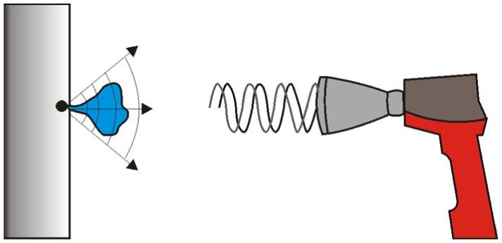
The use of an ultrasonic leak detector.
In the place of air leakage in pneumatic systems, a temperature change is created as a result of the expansion process. A novel air leak diagnosis and localization method based on IR thermography is described in papers.19–21 IR technology uses thermovision cameras to display and measure thermal energy radiated by an object. Those cameras allow a very accurate non-contact temperature measurement (Figure 3).
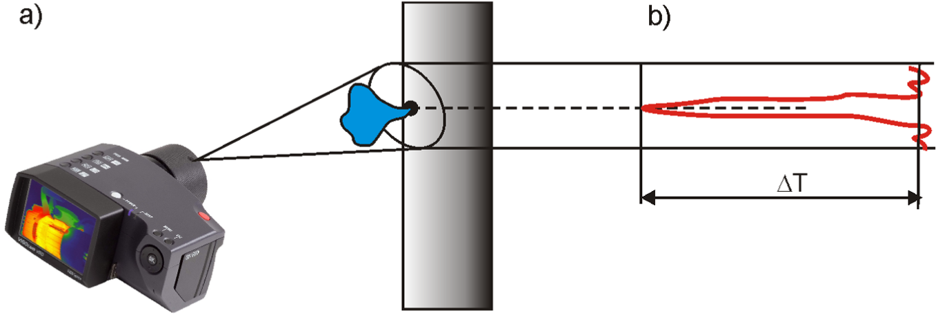
Infrared leak-detection technology: (a) thermovision camera and (b) temperature distribution in the leak point.
Direct measurement method
The direct measurements of flow rate are primarily applied to measure the air consumption in pneumatic plant and to determine the performance data of compressors. The flow metre installed on main distribution lines can show an increased leakage and waste of compressed air in pneumatic pipeline system. The direct method of measuring leakage with a flow metre requires placing the flow metre in the pipeline or on its bypass. The disadvantage of this method is the need to adjust the measuring range of the flow metre to the leak in the pneumatic system. In addition, the installation of the flow metre is expensive, and the size of the leakage varies. In order to reach sufficient resolution of flow rate, the optimum measurement range should be close to the operating range. If the flow rate falls below 10% of the maximum measured value, the measurement accuracy decreases.22,23
For the measurement of the flow in pneumatic pipelines, a flow station or compressed air counter is usually used. The large measuring range of the flow station DS 300 enables the recordings of consumptions and the determination of leakages in pneumatic systems. 24 The Testo 6441 compressed air counter enables you to carry out accurate compressed air consumption measurements, consumption and leak monitoring, and flow measurements in the CAS. 13 Most of the measuring devices are connected to the pipe of pneumatic plant. As a result, their installation is difficult and expensive. The thermal flow metres are connected by the ball valves, and compressed air counters are directly integrated with the pipe of pneumatic system (Figure 4).
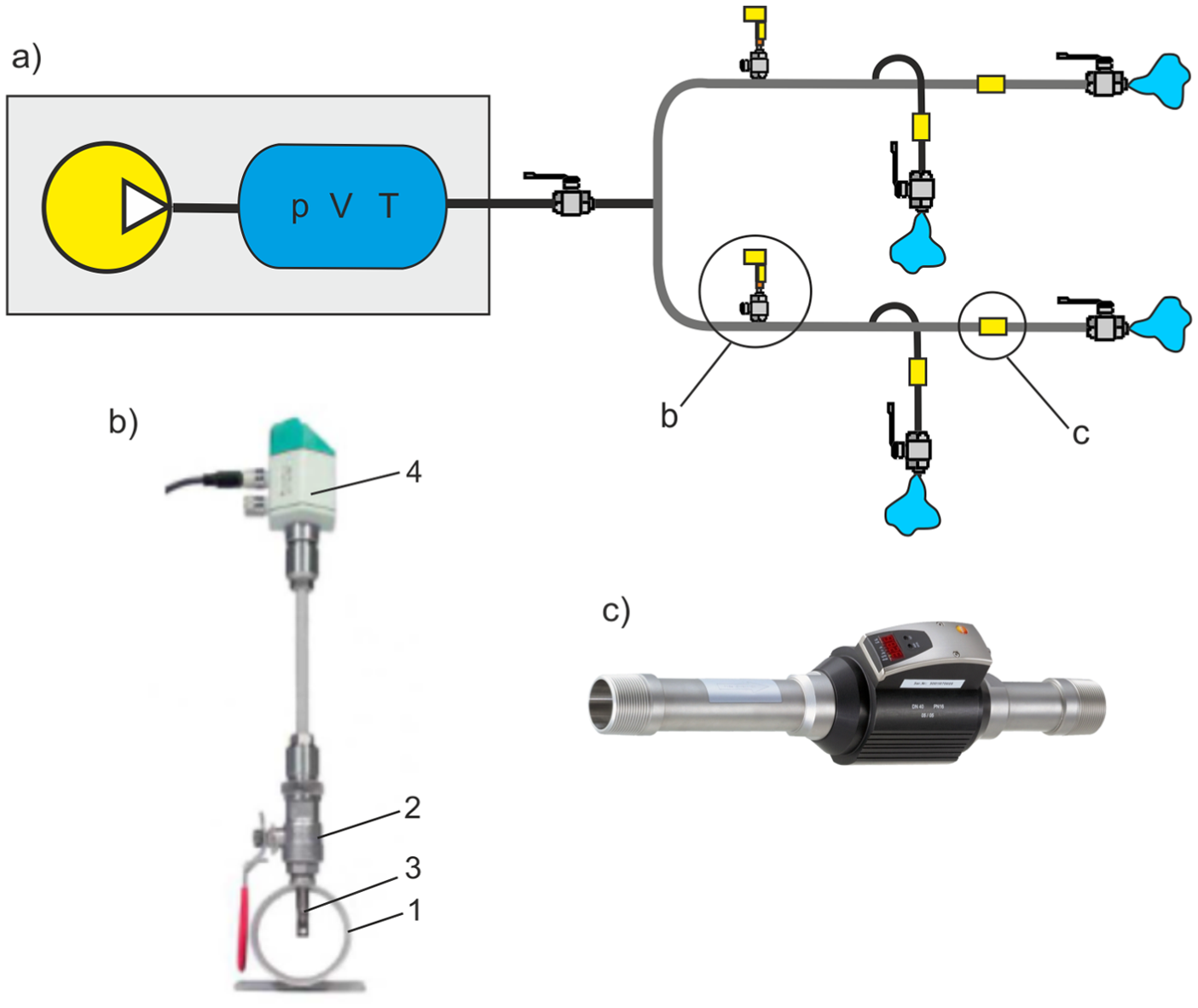
Direct measurement of leakage flow rate: (a) diagram of pipeline systems, (b) measuring point (CS Instruments), and (c) compressed air counter (testo) integrated with the pipe.
Indirect standard measurement method
Indirect measurements of flow rate primarily serve to determine air consumption, leakage values, and characteristics of CASs. The advantage of the indirect measuring method compared to direct measurement is that it does not require expensive measuring equipment. The indirect measurement method of leakage flow rate consists in the measurement of the pressure drop in pneumatic piping system. All it takes is for the pressure sensor to be integrated with the piping. The pressure can be measured and recorded over a longer period of time at short intervals. In this measurement, it is required that all end-use equipment is turned off. The diagram of the CAS containing symbolic leak point is shown in Figure 5. The diagram was used to calculate the leakage flow rate using the indirect measurement method.
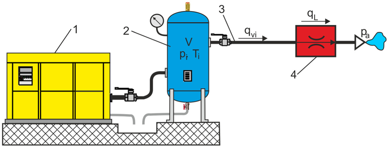
Diagram of compressed air system.
Theoretical basic of indirect measurement method
A mass flow of compressed air in the pneumatic pipeline is written as
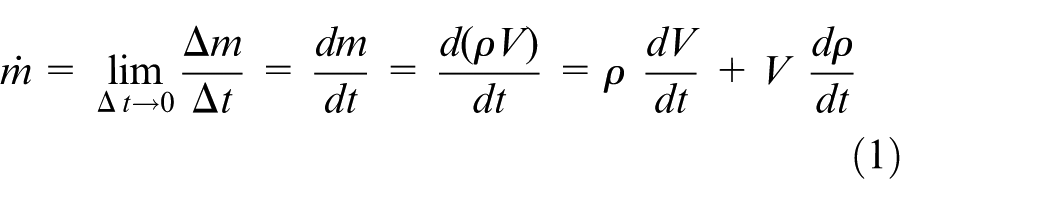
where m is the mass, ρ is the density, and V is a storage volume of air receiver tank and piping.
For a constant volume V (V = const) of the compressed air pipelines, the left component of the right-side of equation (1) is omitted, and we obtain
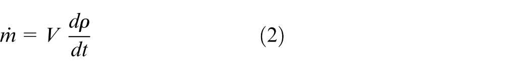
Equation (2) for the i-th polytropic process of a perfect gas is written as follows
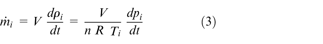
where Ti, pi are the actual absolute values of temperature and pressure, respectively; R is the specific gas constant, for dry air 287 J/(kg K), n is the polytropic index.
Based on equation (3), taking into account the Clapeyron equation for ideal gas, the volume flow rate qi for i-th state of compressed air in a pneumatic pipeline is written as
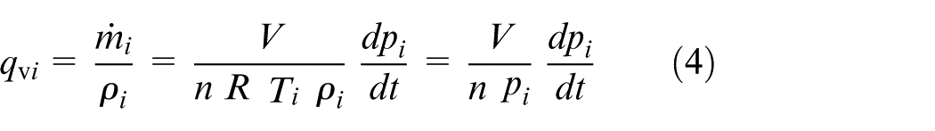
The leak of compressed air in pipelines takes place in time-varying pressure decrease dpi/dt and at almost constant temperature Ti = idem. When compressor and all the air-operated end-use equipment are turned off, the leakage flow rate qL in leaks points of pipelines takes place (Figure 5)

For a small pressure drop dpi/dt, it can be assumed that the flow rate qL through leak orifices for choked conditions is steady (qL ≈ const).
Estimation of the leak flow rate by measuring the pressure drop
Indirect standard method is based on the estimation of the leak flow rate by measuring the pressure drop, while the compressed air receiver tank is being drained (Figure 5). The method requires the estimate of total system volume V, including all air tanks and air mains piping. The system is started and brought to the required operating pressure p1. Measurements should then be made of the time interval Δt necessary for the pressure drop (1–2 bar) to a lower pressure p2. Based on formulas (4) and (5), the volumetric leak flow rate qL in isothermal atmosphere (n = 1, Ti = Ta = const, pi = pa) and differential variables (dpi = Δpi, dt = Δt) can be calculated as follows
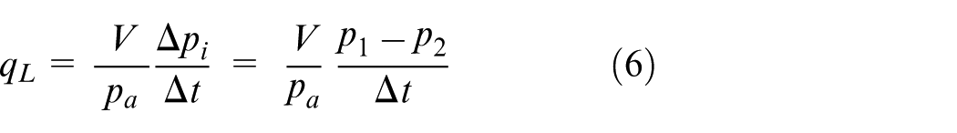
where Δpi is the pressure drop, p1 is the operating pressure, p2 is the lower pressure, pa is the atmospheric pressure, and Δt is the time interval.
Estimation of energy losses due to leaks in the pneumatic pipeline
The basic indicators of pneumatic pipeline system resulting from leakage flow rate qL are power losses, PL; specific energy consumption, SEC; annual energy losses, EL; and cost of the annual energy losses, CEL. 25
Power losses PL in kW due to leakage in pneumatic pipelines

where qL is the volumetric leak flow rate in m3/h, and SEC is the specific energy consumption in kWh/Nm3.
Specific energy consumption SEC is determined from the relation of compressor power PA in kW to the free air delivery qFAD in Nm3/h
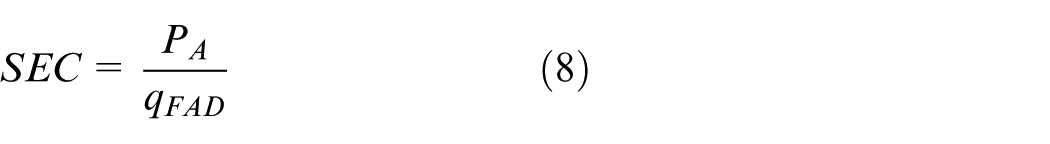
For example, at a pressure of 0.7 MPa, the SEC should fall within the following criteria: 26
Between 0.085 kWh/Nm3 and 0.11 kWh/Nm3 which is a very good ratio;
Between 0.11 kWh/Nm3 and 0.13 kWh/Nm3 which is an acceptable ratio;
Above 0.13 kWh/Nm3, the ratio indicates a problem in the system.
Annual energy losses EL in kWh/yr due to the annual leakage in pneumatic pipelines

where HL is the annual leakage in h.
The cost of the annual energy losses CEL in €/yr due to the annual leakage in pneumatic pipelines

where ER is the energy rate in €/kWh.
Leakage can frequently amount to 15%–25% of the produced compressed airflow. Since leak flow is also proportional to the working pressure one method of reducing leakage involves lowering of the working pressure. Two demands are placed on a compressed air distribution system: a low-pressure drop between the compressor and the point of consumption and a minimum of leakage from the piping systems. Lowering the pressure by only 0.3 bar reduces leakage by 4%. If the leakage in an installation of 100 m3/min is 12% and the pressure is reduced by 0.3 bar, a saving of approximately 3 kW is achieved. 27 Even a small leakage in orifice with a diameter of only 5 mm in a 6 bar compressed air network has expensive consequences, that is, air losses of 30.9 L/s, whose cost is over €4000 per annum. 26 Energy costs are clearly the dominating factor in the pneumatic pipeline system’s overall cost. Compressed air leaks are often not noticed and can ‘silently’ cause a lot of unnecessary costs, even during production downtime or over the weekend.
Indirect measurement method based on the standard flow in branch line
In the papers,28,29 a measurement method with parallel connection for gas leakage flow based on standard flow is developed. An instantaneous method for measuring leakage flow rate in pipeline is enabled by employing standard flow. Measuring equipment can be connected to the pipeline in parallel, which guarantees both convenience and non-destruction. Standard flow is used to determine the internal volume of the measured equipment. A nonlinear discrete-time tracking-differentiator has been designed to track the differential pressure. An algorithm describing the relationship between leakage and standard flow is formulated. To match the leakage flow rate, three different types of pilot valves with standard orifices of 1, 2, and 3 mm, respectively, and maximum pressure up to 1.0 MPa are applied. Similar measurement method of leakage flow rate in pneumatic pipelines system based on the standard flow through fixed calibrated orifice valve in branch line is shown in Figure 6. 11
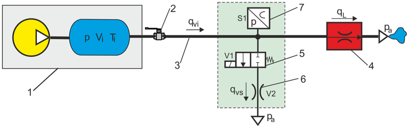
Diagram of the measuring system based on the standard flow in a branch line.
In measurement system, the leakage flow rate qL in pipeline is determined by the pressure drop Δp in time interval Δt– without standard flow (Δp1 in Δt1), when 2/2-way directional valve is closed and with standard flow through calibrated orifice (Δp2 in Δt2), when 2/2-way directional valve is open (Figure 7).
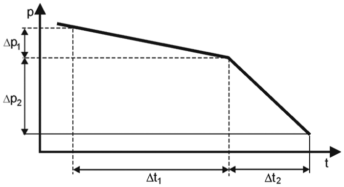
Pressure drop during measurement of compressed air leakage without and with standard flow in branch line.
A calibrated fixed orifice 6 is a very practical and relatively cheap measuring device for flow rate measurement with good accuracy. Fixed orifice valves are available for use in pneumatic control circuits, which provide restricted flow in one direction. The pressure drop Δp2 in the orifice valve is directly proportional to the choked flow rate qvs of compressed air. The indirect measurement method involves determining the relation between air leakage flow rate qL in leak point of pipeline 4 and the standard airflow rate qvs through the calibrated fixed orifice 6. The volume flow rate equation (4) in two states of the air leakage in compressed air pipeline system are written as
For air leakage without the standard flow (qvi = qL, pi = p1, dpi = Δp1, dt = Δt1)
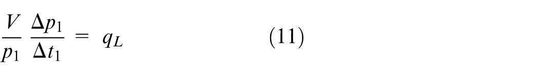
For air leakage with the standard flow (qvi = qL + qvc, pi = p2, dpi = Δp2, dt = Δt2)
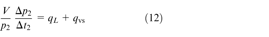
where qL is the total air leakage flow rate through the leak point of a pipeline, qvs is the standard volumetric flow rate through calibrated orifice, Δp1 is the pressure drop during leakage without the standard flow, Δp2 is the pressure drop during leakage with the standard flow, Δt1 is the time period during leak without the standard flow, Δt2 is the time period during leakage with the standard flow, p1 is the absolute pressure in time period during leakage without the standard flow, and p2 is the absolute pressure during leakage with the standard flow.
The conversion of equations (11) and (12) results in the following formula used to calculate the air leakage flow rate based on the standard flow in a branch line
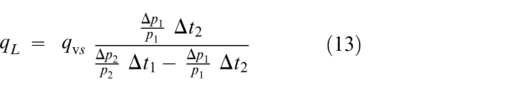
The disadvantage of this measurement method is the need to determine the relative pressure drop Δpi/pi and to properly match the calibrated fixed orifice with the leakage.
New indirect measurement method based on the controlled flow in branch line
In previous works, a new approach to the method of measuring the compressed air leak was proposed. It was based on flow measurement of flow rate through a controlled valve in the branch line.30,31 To measure the leakage flow rate in a branch line, a flow metre and an adjustable control flow valve were used. The adjustable control valve enables the adjustment of the controlled flow to the leakage range in a compressed air pipeline. Thus, it is possible to measure the leakage flow rate in a wide range, from very small (local) values to very large ones, for example, during a severe damage to the pneumatic equipment. An advantage of using the flow metre in a branch line, as compared with the standard flow through a fixed orifice, is that the knowledge of the flow characteristics, control valve parameters, and the volume of receiver and pipeline is not required. The proposed method is convenient and practical for automatic measurement of the leakage flow rate in any compressed air pipeline system. A diagram of the leakage flow rate measurement system used in compressed air pipelines, based on the controlled flow in a branch line is shown in Figure 8. The measurement method of compressed air leakage in pipelines based on the controlled flow consists in determining the relation between the air leakage flow rate ql in a leak point of pipeline and the controlled airflow rate qvc directly measured by the flowmeter in a branch line. 32
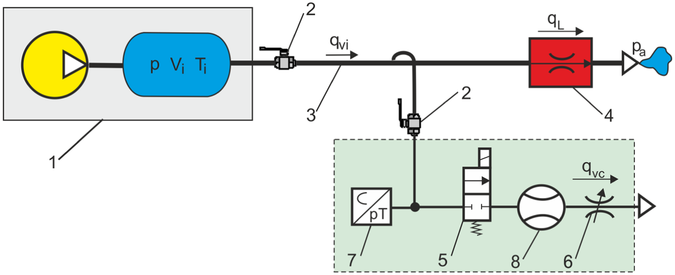
Diagram of the measurement system based on the controlled flow in a branch line.
With the new indirect method, the compressed air leakage is estimated by the measurement of pressure drop ratios in time intervals (Figure 9):
For the leakage measurement without the controlled flow, when control valve 5 is closed, the pressure drop ratio pLu/pLd in the time interval tL is measured.
For the leakage measurement with the controlled flow, when control valve 5 is open, the pressure drop ratio pLcu/pLcd in the time interval tLc and the flow rate qvc are measured.
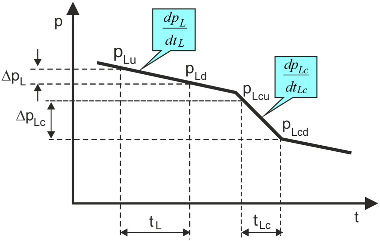
Pressure drop ratios in compressed air pipelines during the measurement of leakage flow rate based on the controlled flow in a branch line.
The compressed airflow equations in two states, for air leakage without and with controlled flow determined from equation (4) are written as:
For air leakage without the controlled flow (qvi = qL, pi = pL, dpi = dpL, dt = dtL)
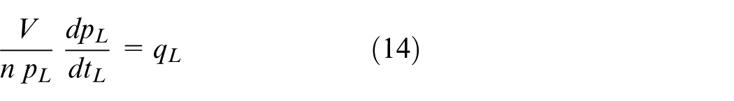
For air leakage with the controlled flow (qvi = qL + qvc, pi = pLc, dpi = dpLc, dt = dtLc)
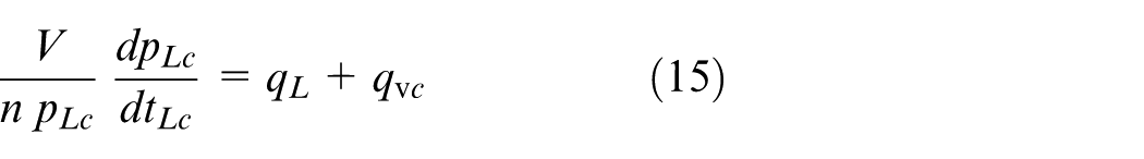
where qL is the total air leakage flow rate through the leak point of pipelines, qvc is the average volumetric airflow rate through the adjustable throttle valve (measured by a flow metre), pL is the measurement absolute pressure during leakage without the controlled flow, pLc is the measurement absolute pressure during leakage with the controlled flow, tL is the measurement time during leakage without the controlled flow, and tLc is the measurement time during air leakage with the controlled flow.
Since the leakage airflow rate in leak points of pipelines is unsteady the differential equations (14) and (15) were transformed by logarithmic function to the following form
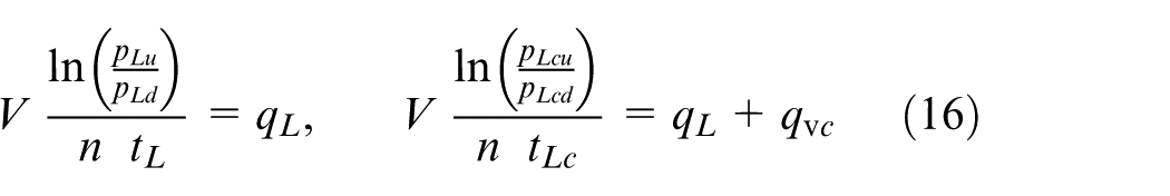
where pLu, pLd are the upstream and downstream measurement pressure during leak without the controlled flow, respectively, and pLcu, pLcd are the upstream and downstream measurement pressure during leak with the controlled flow, respectively.
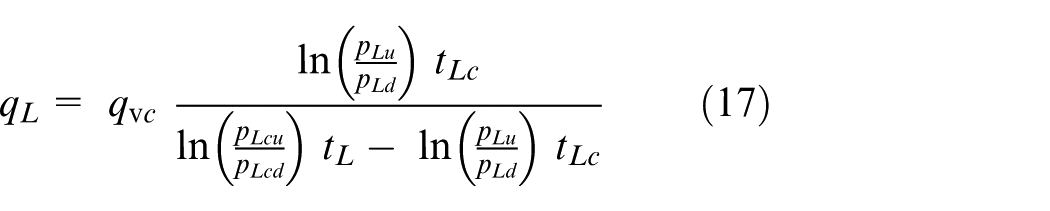
The conversion of equation (16) results in the following formula used to calculate an air leakage flow rate based on the controlled flow in a branch line
Then, a practical formula for calculating the total flow rate of leakage in a CAS using the indirect method with the controlled flow in a branch line has the form 31
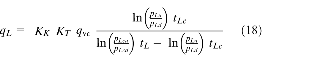
where KK is the calibration factor dependent on the measurement conditions, and KT is the correction factor dependent on the temperature measurement
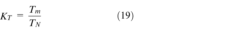
where Tm is the temperature of measurement, TN is the temperature at Atmosphere Normale de Reference (ANR) conditions of reference, TN = 293.15 K (20°C).
If the internal pressure decreases rapidly, then the temperature has to be considered. The flowchart of measurement method for the estimation of leakage flow rate for measured values (pm, Tm, qvcm) is shown in Figure 10 in accordance with equation (18).
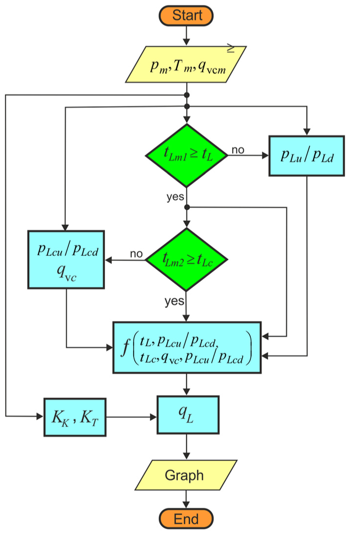
Flowchart of measurement method.
In order to measure the leakage flow rate in pneumatic pipelines by means of a new indirect method with controlled flow in branch pipeline, the measurement and control system (CS) was constructed.
Portable measuring device LT-I 200
The advantage of portable leak-testing instrument LT-I 200 is the ability to conduct direct and indirect measurement of leakage flow rate while testing the pneumatic pipeline systems. Direct and indirect measurement will allow us to check the leakage measurement error of LT-I 200 portable measuring device. The measurement scheme of LT-I 200 portable measuring device, based on the controlled flow in the branch line is shown in Figure 11. The measurement system consisted of thermal flow metre 1, pressure and temperature transducer 2, 3/3 (3-way, 3-position) directional valve (electrical operated) 3 and adjustable throttle valve 4.
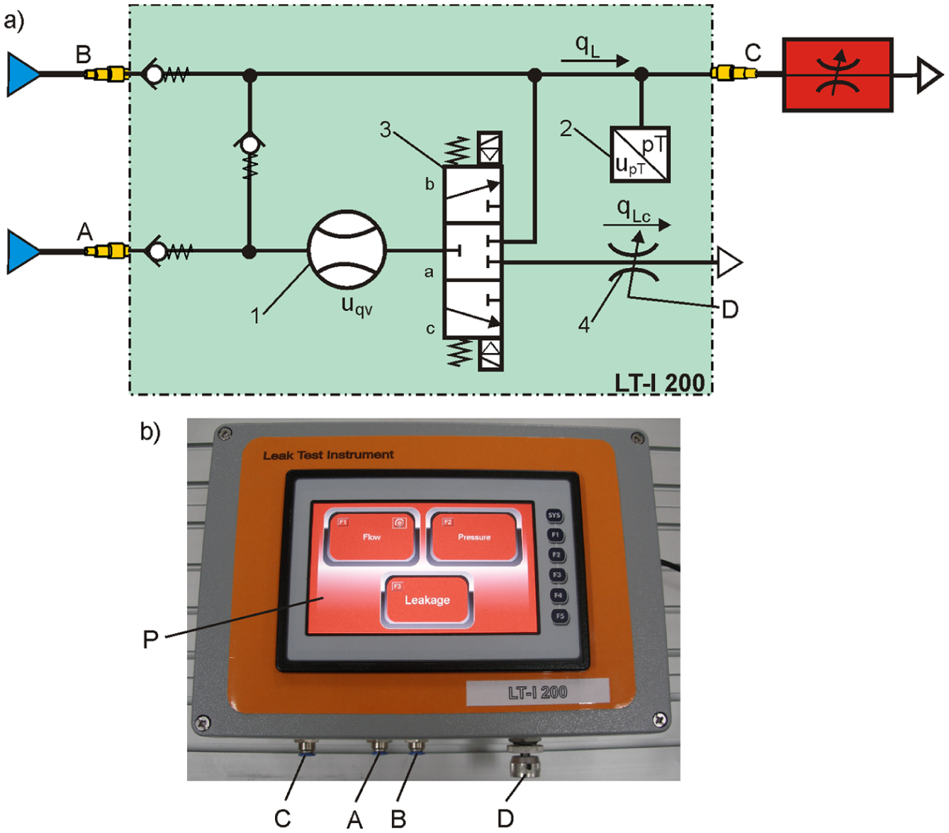
Portable measuring device LT-I 200: (a) measurement diagram and (b) view of the device.
The measuring procedure using LT-I 200 device makes it possible to measure the leakage flow rate in the test pipeline in a semiautomatic way.
Direct measurement of the leakage flow rate qLm, when device is connected to the connector A and valve 3 is in position a;
Indirect automatic measurement of the leakage flow rate qL, when device is connected to the connector B and valve 3 is in position b (first measurement without controlled flow), and then in position c (second measurement with controlled flow), but the throttle valve 4 must be manually set by control knob D prior to the measurement;
Adjustable throttle valve 4 is used to determine value of the controlled leakage flow rate qvc in branch line;
Thermal mass flow metre 1 (TSI 4043) measures the volumetric flow rate qv, measuring range is 0–200 L/min, measured error <±2% of measured value;
Dual pressure and temperature transducer 2 (ATM/T) provides two independent voltage or 4–20 mA outputs from a single device;
Pressure transducer measures the compressed air pressure p(t) to 1 MPa (10 bar);
Temperature transducer measures the compressed air temperature T(t) to 423 K (150°C);
The device performs a measurement process in accordance with equations (16);
As a result, the device automatically measures the value of leakage flow rate qL in compressed air pipeline.
Advanced features:
Compact device size is 330 × 230 × 180 mm;
Integrated colour touch display WVGA (800 × 480), with a high-resolution resistive touch screen (16-bit colours);
Dual 10/100 Ethernet for Factory and World-wide Networking – supporting Modbus/TCP Master/Slave, FTP, and HTTP;
Two RS232/RS-485;
USB 2.0 flash drive support – transfer files between the internal micro SD and the USB flash drive, USB port for easy programming and application loading;
1 MB memory, 32 GB flash memory storage;
Power of 230 V AC (24–30 V DC).
The LT-I 200 measurement device (MD) is configured with membrane keyboard and touch screen P on the front panel. The touch screen device has the basic functions for measuring the leakage in CASs:
F1 – direct measuring of the leakage flow rate;
F2 – measuring of the pressure drop ratio;
F3 – indirect measuring of the leakage flow rate;
F4 – view of device function;
F5 – view of measurement results of pressure pLu, pLd in time intervals tL, pressure pLcu, pLcd and flow rate qvc in time intervals tLc, and also the calculation results of air leakage flow rate qvL in the tested pneumatic pipeline.
The calibration of the measuring instrument has been carried out so that the test measurements are made within the range of the leakage. Measurement results can be transferred to graphical software such as LabVIEW. Figure 12 shows the view of panel with measurement results and two pressure measuring windows: the upper for first time interval without the controlled flow and the lower one for the second time interval with the controlled flow in branch line.
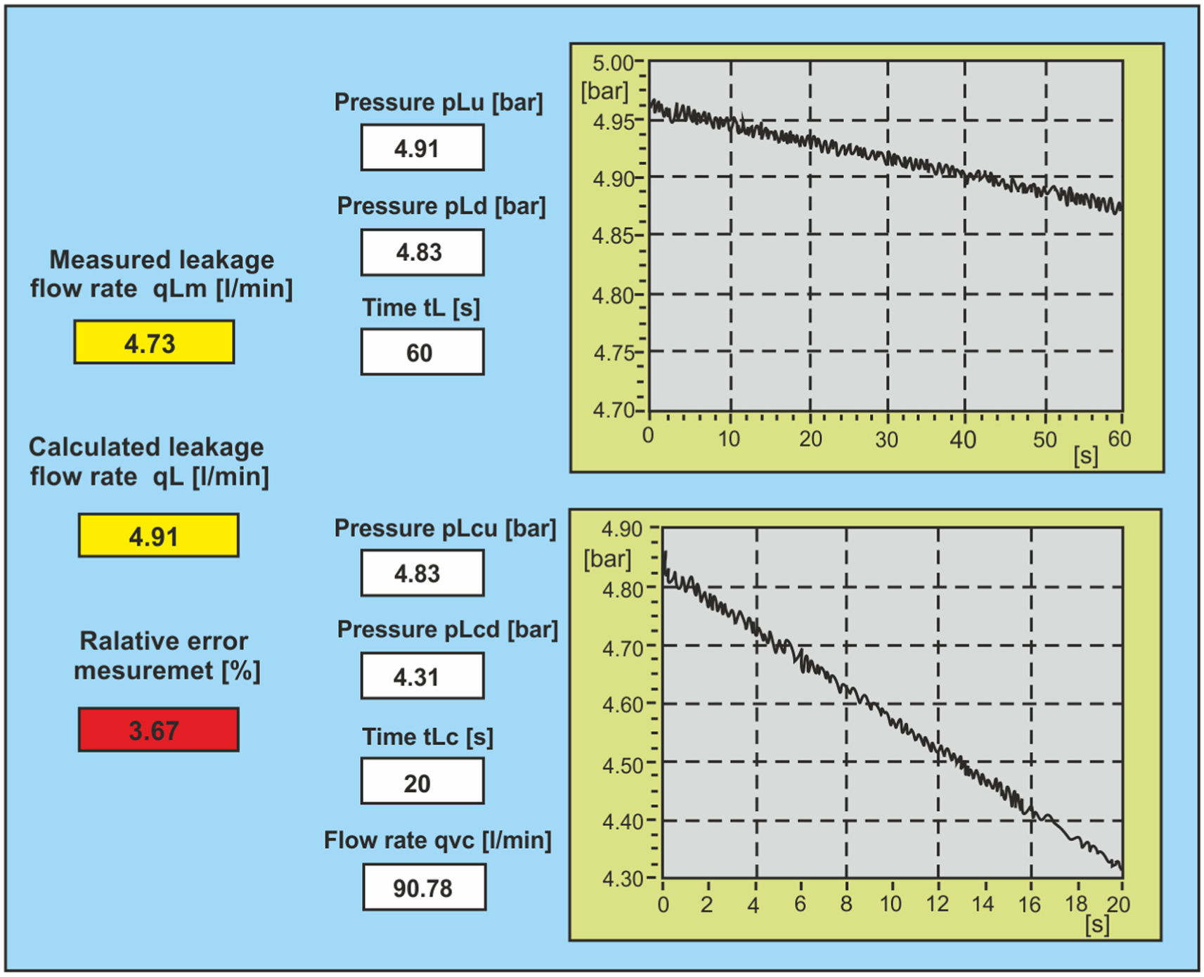
View of panel showing results and graphs of the measurements.
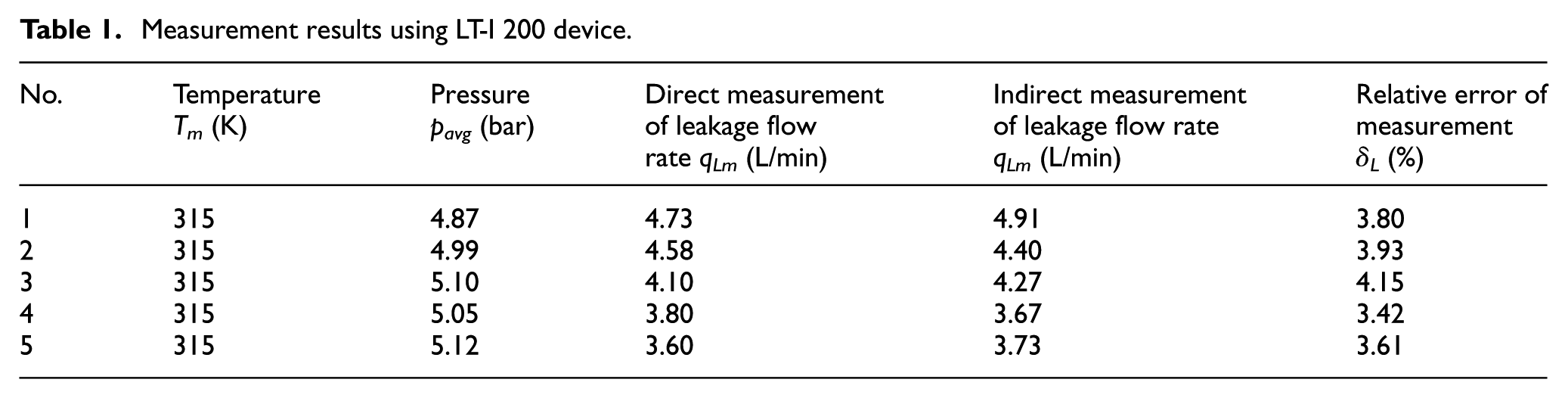
The direct and indirect measurements of the leakage flow rate in the tested pneumatic pipeline were conducted in accordance with measuring principle of LT-I 200. To compare the direct and indirect measurement results of leakage flow rate in the tested pneumatic pipeline, a relative error δL was calculated according to the equation
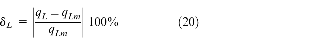
where qLm is a direct measurement value of leakage flow rate, and qL is an indirect measurement value of leakage flow rate.
An example of measurement results is shown in Table 1.
Measurement results using LT-I 200 device.
The portable MD LT-I 200 was awarded with the medal for the innovative product on the 8th Exhibition of Pneumatics, Hydraulics, Drives and Controls PNEUMATICON’2015 in Kielce International Trade Fairs (Poland).
AMS
Finally, a patented AMS for automatic indirect measurement of the leakage flow rate in a pneumatic pipeline was developed. 31 A schematic of the AMS system for indirect measurement of the leakage flow rate connected to a branch of the pneumatic pipeline is shown in Figure 13.
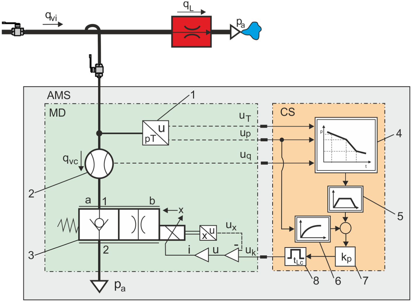
The schematic diagram of an automatic measurement system for indirect measurement of leakage flow rate on the branch of the pneumatic pipeline.
The MD comprises a pressure and temperature transducer 1, a thermal flowmeter 2, and a special 2-way/2-position bifunctional pneumatic proportional control valve 3. The CS contains a calculation module of leakage 4, a calculation module forming the reference signal 5, a calculation module of the valve flow rate 6, a control unit 7, and a valve-setting unit 8. The CS is designed to work with the MD that reads out voltage signals from the pressure and temperature transducer 1 (uT, up) and the thermal flowmeter 2 (uq). The CS also generates an output voltage signal (uk) to the 2/2 proportional control valve 3. The valve-setting unit 8 limits the set signal tLc. The 2/2-way bifunctional pneumatic proportional control valve 3 of a novel design is shown in Figure 14. This valve performs two control functions: in the closed position a, it functions as a shut-off valve, whereas in the open position b, it functions as a proportional throttle valve. The measurement of leakages by means of the CS includes: calibration, measurement without the controlled flow, and measurement of the controlled flow.
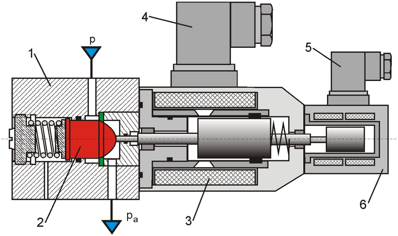
The view of cross-section of the 2/2-way bifunctional pneumatic proportional control valve.
During the measurement path calibration in a constant time tLc, the pressure drop through valve 3 is defined. On the basis of the measured pressure p in the pipeline, the critical pressure pcr approaching the values for a choked flow in control valve 3 is determined. By measuring the time constant τ of the compressed air discharge from a pneumatic valve, a set time tLc is selected. When the measurements of leakage without the controlled flow are performed, and control valve 3 is closed, module 4 records the upper pLu and lower pLd pressure values in tL, which enables us to determine the pressure drop ratio pLu/pLd caused by the leakage qL of compressed air in the pipeline. Then, when the measurements of leakage with the controlled flow are carried out, and control valve 3 is opened, block 4 records the upper pLcu and lower pLcd pressure values in tLc, which enables the determination of the pressure drop ratio pLcu/pLcd due to the leakage in the pipeline as well as the valve flow to the atmosphere. To carry out the controlled flow, the block forming control unit 7 that generates a voltage of a limited duration tLc at the control valve 3 input was used. To keep the measurement time for a constant flow rate qLc through control valve 3, a feedback signal from the valve determines the adjustment error. Time pulse voltage up to the control valve 3 is determined in the range of tLc = 5–50 s. After measurements are completed, the leakage flow rate qL is calculated according to equation (18). The results of measurements of parameters p(t), qvc(t), and calculations of leakage flow rate qL for the analysed samples are shown in Figure 15. It is observed that during the transition from the first to the second measuring interval, after the valve has been activated, the pressure disturbances take place.
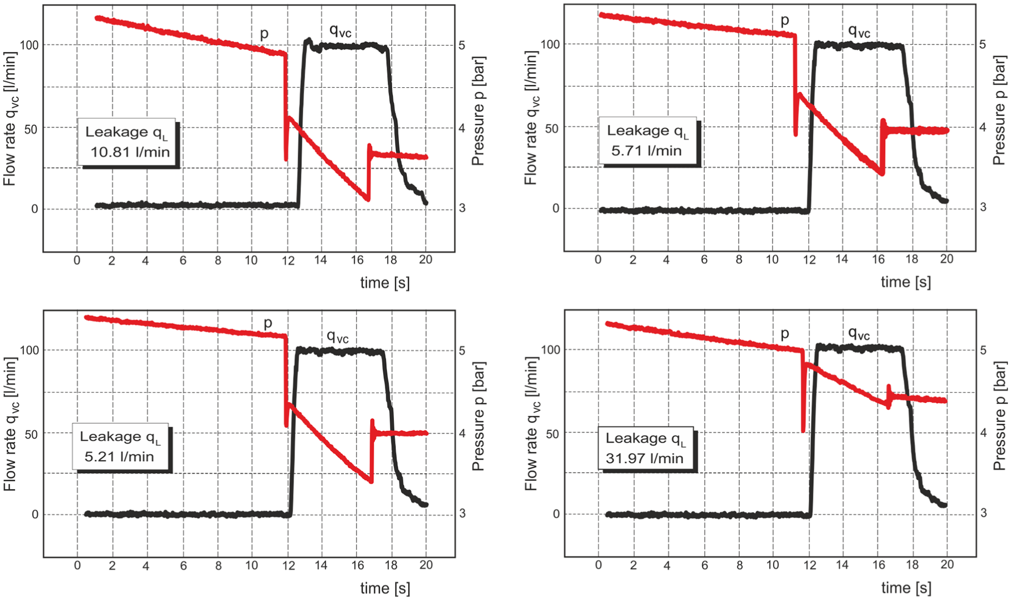
A sample graph of the measurement results of flow rate qvc(t), pressure drop p(t), and leakage flow rate qL.
The authors compared the AMS in terms of costs with similar products available on the market. The comparison shows that only a programmable control panel (the measurement transducers are not taken into account) can be half the price of that offered by various companies. The proposed AMS system will be used in the new research project ‘Mobile laboratory for the audit of compressed air systems’. The leak-detection equipment will be used to locate and remove leaks, calculate both the leakage flow rate in pneumatic pipeline systems and financial losses caused by compressed air leaks.
Conclusion
A new method of indirect measurement of flow rate in pneumatic pipeline system was developed by the authors. The method allows for the measurement of the controlled leakage in a branch line and was used to construct AMSs for the CASs audit. First, the leak-testing instrument LT-I 200 was designed, constructed, and tested as portable MD for the estimation of air leakage flow rate in pneumatic pipeline system. The device was used to test the accuracy of the measurement method and to compare the direct and indirect results of the leakage flow rate to those in a standard pneumatic pipeline. After measurements were made for the same initial conditions, it was found that the error of leakage measurement did not exceed 5%. The results of the measurements are compared with the results of a traditional method using pressure losses in the pipeline. When considering an overall audit accuracy requirement, the effect of cumulative measurement errors and manufacturer data inaccuracies must be taken into account. A measurement error of less than 1% is subject to audit costs. After testing LT-I 200 measuring device, the factors that influence the accuracy of the measurements were either eliminated or minimized, for example, pressure pulsation after excessive control of directional control valve and maintenance of choked flow through the throttle valve. If the pressure decreases rapidly and the leakage flow rate is high, the temperature has to be considered. Next, based on the authors’ patent, the automatic AMS for the measurement of the leakage flow rate in industrial compressed air piping was developed. The AMS consists of an MD and CS. In the MD, a novel bifunctional pneumatic proportional control valve was used. The AMS system can be used to measure leakages at any time and in any place of the pipeline: in the main pipeline, distribution line, or the line connecting to pneumatics equipment (machines and tools). Compared with traditional measurement method, MS system can be connected to air pipeline easily, which makes it applicable in pneumatic pipeline plants. The measurement is non-invasive, as it does not interfere with the existing machines.
Footnotes
Declaration of conflicting interests
The author(s) declared no potential conflicts of interest with respect to the research, authorship, and/or publication of this article.
Funding
The author(s) received no financial support for the research, authorship, and/or publication of this article.