
Abstract
Background:
Spindle imbalance vibration of the computer numerical control grinding machine may result in dramatic effects on tool wear, surface finish, and form-holding of the products, which makes the balancing procedure very essential during their manufacturing process. Although the spindle residual vibration in a single direction can be suppressed effectively by the commonly used commercial balance systems, some real-world application results show that most of these balance systems cannot reduce the spindle residual vibration in horizontal, vertical, and axial direction simultaneously.
Methods:
To overcome this issue, the limitation of commonly used influence coefficient method–based spindle balance method is discussed first. After that, a novel balance method is experimentally proposed for the spindle vibration control using the position fluctuation information between the carriage and guideway of the servo-axis. In this method, the position fluctuation information between the carriage and guideway and the key phase information are practically measured using the built-in linear scale and spindle servomotor encoder, respectively, in which the position fluctuation information between the carriage and guideway can be considered as an integrated representation of the spindle imbalance vibration. Combined with the influence coefficient method, the imbalance vibration presenting in the horizontal, vertical, and axial direction of the spindle can be suppressed simultaneously and effectively.
Results and Conclusions:
A field balancing experiment is carried out on a high-precision computer numerical control gear grinding machine. Experiment results demonstrate that, compared with the commonly used commercial balancing system, the proposed method can not only reduce the residual vibration amplitude at the objective balancing speed effectively but also reduce the residual vibration amplitude more than 50% simultaneously in each direction during the whole run-down process.
Keywords
Introduction
Grinding is usually considered as the finishing machining process for gear manufacture industry because of its advantages in higher machining accuracy and tooth flank errors elimination. 1 Generally, there are two main methods for cylindrical gears grinding—the form grinding method developed by Höfler, Niles, and Gleason and the generating grinding method developed by Reishauer and Gleason, which can be considered as the single-indexing process and continuous-indexing process, respectively. To improve the grinding efficiency while simplifying the structure, high-speed spindles are widely used in these modern computer numerical control (CNC) grinding machines. However, during their service progress, most of the spindles are suffering from the imbalance vibration which often results by incorrect mounting of the wheel, varying widths of the wheel, coolant absorption into the wheel, imbalance in the mandrel or arbor, and so on. 2 Besides, in precision grinding process, the cut depth is often so small that even the slightest vibration amplitude can have dramatic effects on tool wear, surface finish, and form-holding of the products. 3 Thus, balancing procedure for spindle system is very essential for improving product qualification, achieving longer bearing life, and reducing the unscheduled shutdown times reducing. 4 Currently, most of the balancing procedures are implemented with off-line balancing method. To overcome the drawbacks of the off-line balancing method, some commercial on-line balancing systems are developed and widely employed in CNC grinding machines such as Niles, Höfler, and Reishauer. However, practically imbalance vibration often presents in the horizontal, vertical, and axial direction of the spindle simultaneously. Some real-world application results show that most of these on-line balance systems, such as SBS balance system and Dittle balance system, cannot simultaneously reduce the residual vibration in horizontal, vertical, and axial direction, although the spindle vibration in a single direction can be suppressed very well at the object operating speed. In this study, a novel balance method is experimentally proposed for the spindle vibration suppression using the position fluctuation information between the carriage and guideway (PFICG) of the servo-axis. This method can be considered as a sensorless balancing method because the PFICG and the key phase information are practically measured by built-in linear scale and spindle servomotor encoder of the CNC grinding machine.5,6 Compared with the current used method, this method has its advantages as follows:
Built-in sensors, such as encoders and linear scales, always directly connect with the mechanical components. 7 The PFICG of the servo-axis obtained from built-in sensors usually contain useful information of the mechanical behavior of spindle system and often keep high resolution and signal-to-noise ratio (SNR).8,9 More importantly, experimental results show that the used PFICG can be approximately considered as an integrated representation of the spindle system vibration.
Since that no extra sensors are required in the proposed sensorless balance method, this method can be implemented with low cost. Besides, compared with the traditional methods, this method can be used in more situations and can never be limited by the sensors mounting space.
The remaining parts of this paper are organized as follows: in section “Limitation of commonly used ICM-based spindle balance system,” the limitation of commonly used influence coefficient method (ICM)-based spindle balance system is discussed. After that, a sensorless balance method is proposed in section “Proposed sensorless balance method,” and the procedure of this method is introduced in detail. In sections “Experimental setup” and “Spindle balancing of a high-precision CNC grinding machine,” the proposed methodology is used for field imbalance vibration control of a high-precision CNC gear grinding machine, and the performance of the proposed method is then compared with that of the commonly used commercial balancing systems. Finally, conclusions are given in section “Conclusion.”
Limitation of commonly used ICM-based spindle balance system
Review of the ICM
Because of its advantages such as easier to carry out and requires very little knowledge of the rotating system, ICM is widely employed in commercial on-line balancing systems for field balancing of the CNC grinding machine. ICM is originally proposed by Goodman, 10 verified by Tessarzik et al., 11 and implemented with the assumptions as follows: (1) the rotor response is proportional to the imbalance within the range of practical interest and (2) the effect of an individual balancing weight on a measuring plane is independent from each other and can be summed up to obtain the total effect. The basic principle of ICM can be described as

where Vw is an vector representing the rotor imbalance response at a specified rotating speed.
The residual vibration Vresidual during balancing can be obtained as

where Vresidual is a vector representing the theoretical residual vibration, and V0 is a vector representing the original vibration.
ICM is an experimental method. Finite element method is commonly used for the imbalanced system response simulation, 12 in which the dynamic equation can be given as follows

where


where

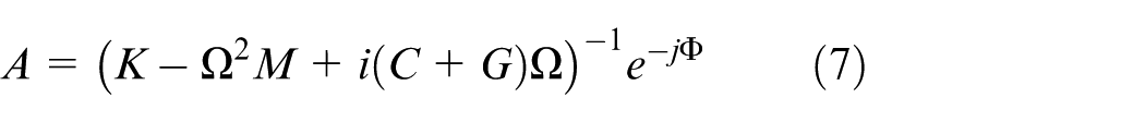
From equation (1), the influence coefficient matrix
Limitation of commonly used spindle balance system
Influence coefficient
In practice engineering, most on-line balancing systems often compose of three parts: the signal acquisition sensor, controller, and mass redistribution actuator. 14 During the balance process, the imbalance information is acquired by accelerometer mounted on spindle housing, after that, the correction mass is calculated by ICM with controller and implemented by a mass redistribution actuator embedded in the spindle. For these balance systems, the correction mass is often calculated by the vibration data obtained from only one direction of the spindle and implements in single correction mass plane. Since that the sensor position m is equated to the correction mass plane n (here, m = n = 1), the residual vibration in this sensor positioned direction can be reduced to zero using these balance systems. However, practical spindle vibration often presents simultaneously in horizontal, vertical, and axial direction (here, m > n, and m = 3, n = 1, so the way to calculate the correction weight is an optimization problem), which makes the single-direction vibration-based commercial on-line balancing systems not appropriate. However, from the theoretical aspect, the multi-sensors-based least-square solution have the ability to suppress the spindle vibration in horizontal, vertical, and axial directions simultaneously by solving the optimization problem when m > n. However, its practical applications are still limited by the effectiveness of problem optimization methods, cost, and sensors mounting space. For this reason, a sensorless balance method is experimentally proposed using the PFICG of servo-axis.
Proposed sensorless balance method
PFICG-based balance method
Figure 1 shows the typical structure of the spindle and carriage-ball screw system of the CNC gear grinding machine, which is often composed of AC servomotor, guideway, precision ball screw, spindle, grinding wheel, and carriage. The PFICG-based balance method is proposed for field balancing of the spindle, and the key idea of this method is that with the turning of the imbalance spindle, the exciting imbalance forces can result in the position fluctuation between the carriage and guideway. Actually, this position fluctuation signature often contains useful information of the mechanical behavior of imbalance spindle system. Besides, the position fluctuation information can be captured by the built-in linear scale on guideway. After decoding, it can be utilized for spindle vibration suppression of CNC gear grinding machine.
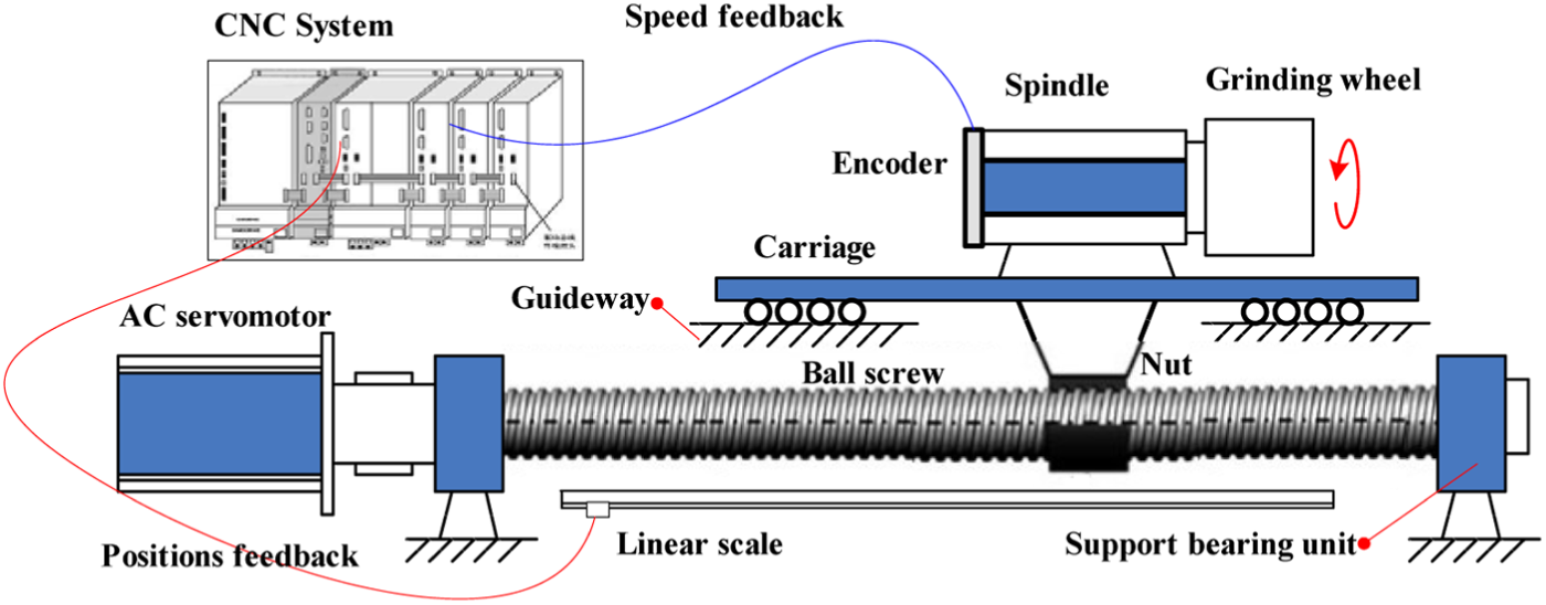
Schematic of the spindle and carriage-ball screw system.
To quantitatively describe the internal relations between the spindle eccentricity and the PFICG of the servo-axis, a model is established after simplifying the structure of spindle and carriage-ball screw system. The schematic model is shown in Figure 2, in which the ball screw is considered as a continuous system, whereas the remaining elements are assumed in the lumped form. In these conditions, the screw can be considered as a straight bar with three fundamental types of deformations: axial deformation resulting from traction or compression, angular deformation resulting from torsion, and flexural deformation. Here, angular deformation is discarded because the servomotor of the servo-axis does not work during the balance process. In this way, the continuous deformation can be represented by an axial displacement field using u(x, t) and by a flexural displacement field using f(x, t). The elements assumed in the lumped form are the rigid bearing with stiffness Kb; the nut with stiffness Kn1, Kn2 and damping Cn1, Cn2; and the carriage and spindle with integral mass Mcs (the carriage and spindle are always rigidly connected with bolts). When the imbalance mass presents in the spindle system, corresponding eccentric exciting force F(t) often presents in the horizontal, vertical, and axial directions of the spindle simultaneously, which may result in an axial deformation and flexural deformation of the ball screw.
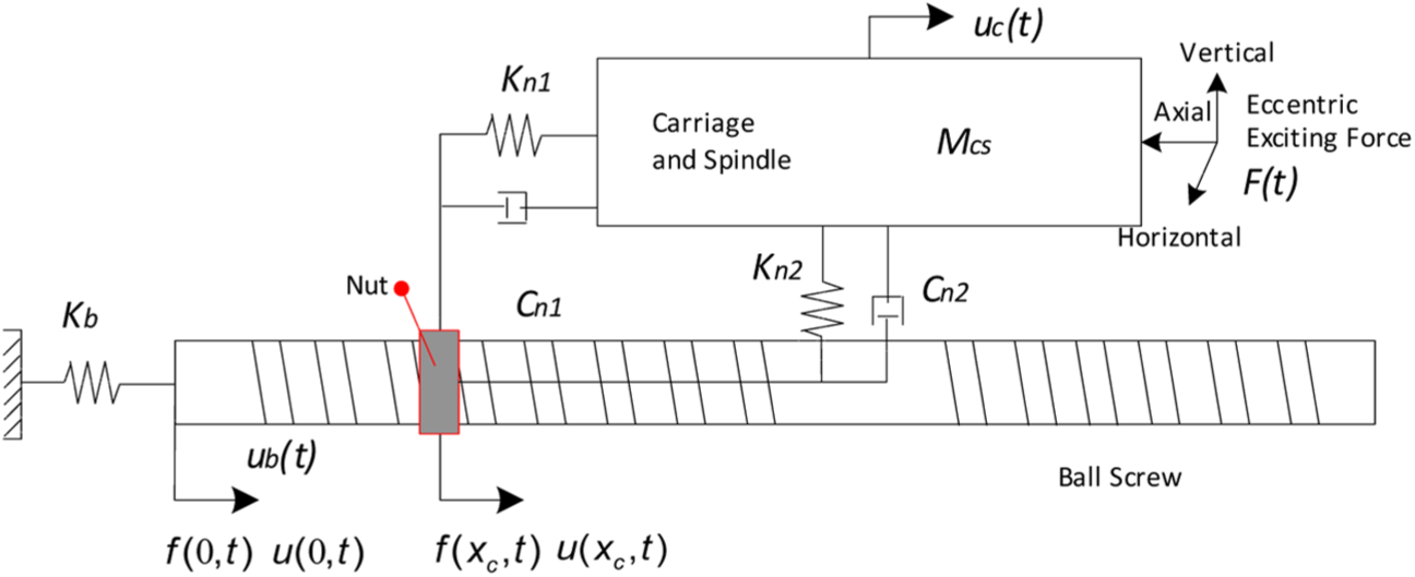
Model of the spindle and carriage-ball screw system.
Suppose that the absolute position of the carriage is uc(t), the translational motion displacement of the ball screw is ub(t), the ball screw length is L, and absolute position of the screw is at the interface-point coordinate xc, then the PFICG can be expressed as

where
Generally, the axial deformations u(xc, t) and flexural deformations f(xc, t) are often obtained using the analytical methods such as Ritz series method. 15 After that, the PFICG can be calculated by equation (8). However, considering the complexity of the modeling, model simplification error, calculation accuracy of analytical method and to make it convenience for spindle field balancing, in this study, the PFICG of the servo-axis is practically measured using the built-in linear scale installed on guideway. Experiments are implemented on the CNC gear grinding machine introduced in section “Experimental setup.” During the experiment, the imbalance mass (3.5 g at ∠0°) is added on the balancing disk of the grinding wheel. In each rotary speed from 2500 to 4000 r/min with increment of 100 r/min, the Y-axis PFICG response amplitudes and spindle vibration amplitudes in horizontal, vertical, and axial directions are measured simultaneously. Figure 3 shows the measured Y-axis PFICG response amplitudes of the imbalance spindle when it is operated at different conditions, which are highly accordant with the amplitude mean of spindle vibration in horizontal, vertical, and axial directions.
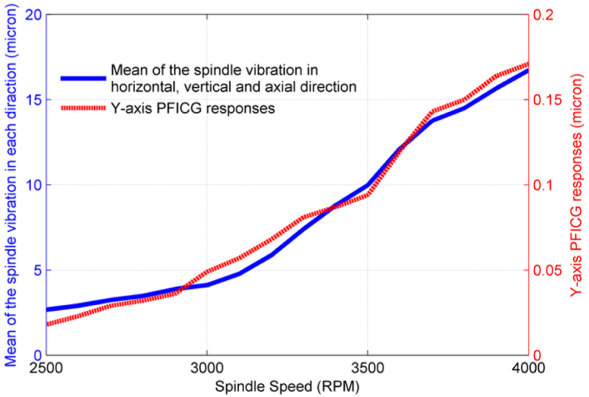
PFICG responses of the imbalance spindle.
Actually, the PFICG is a combination result of the three-direction exciting force, and this experimental result shows that it can be approximately considered as an integrated representation of the spindle imbalance vibration. On this basis, the PFICG-based balance method is proposed by combining with the ICM. Compared with the single-direction vibration used in current balance system, PFICG used in the proposed method can reflect the true vibration of spindle system, which is very helpful for correction mass calculation.
The procedure of PFICG-based balance method
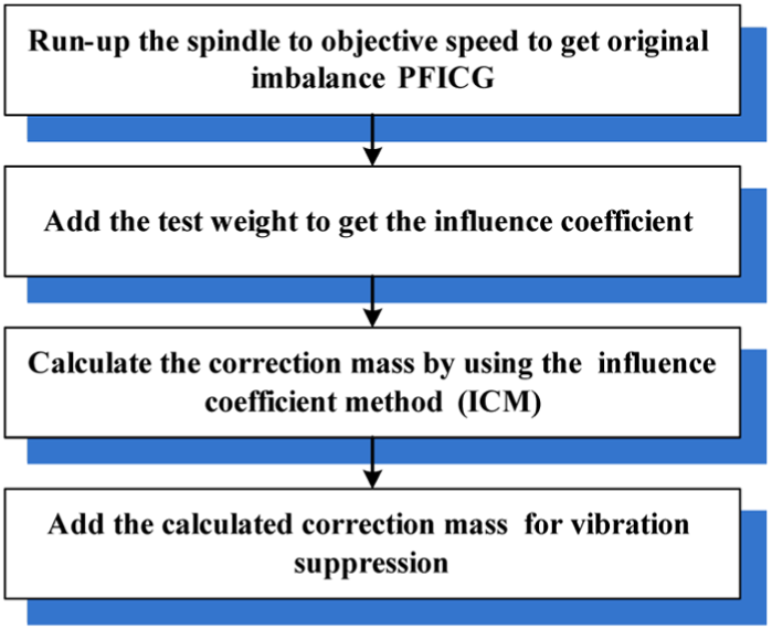
The flow chart for PFICG-based balance method is shown in Figure 4, and its principle and implementation are elaborated as follows:
Step 1. Run-up the spindle to objective speed to get original imbalance PFICG. The PFICG used in the proposed method is captured by the linear scale/encoder which often consists of a slotted linear bar, a light source, and a dual light detector. 16 During the work condition, the light source shines on the linear bar, and the dual light detector mounted on the opposite side of the linear bar captures varying intensities of light as the carriage moves due to the pattern on the linear bar. As the carriage moves, the linear bar moves as well, alternately obstructing and transmitting light between the light source and the detectors. With the light intensity variation, corresponding signals (the form of 1Vpp includes an analog sinusoidal signal pair with amplitude about 1Vpp and a reference signal with amplitude about 0.6 V) are output by the detectors. 17 Figure 5 shows the reference signal of the encoder and the analog signal pair of the linear scale, which are recorded simultaneously when the rotary speed and translational velocity are 300 r/min and 10 mm/min, respectively. After decoding, these signals can be used together to determine the position of carriage. In practice, signal pair obtained from linear scale is often affected by different gains, unknown offsets, thermal drifts, and dirt affecting. 18 Thus, a calibration circuit is needed to eliminate the effect of these factors. After that, the signal can be measured by the counter card, in which the interpolation electronics can subdivide the period of the input signal up to 4096-fold (if the grating pitch of linear scale is 5 µm, the position resolution is 5/4096 = 0.0012 µm). At the same time, the offset, phase, and amplitude of the signal output by sinusoidal encoder and linear scale can be adjusted by software. The overview flow chart for PFICG acquisition is shown in Figure 6. As shown in Figure 6, the signal output by encoder and linear scale often connected directly to the servo driver. Here, two interfaces are used to share these feedback signals. At the same time, the PFICG given by linear scale and the reference information given by encoder of spindle servomotor are sampled synchronously by the counter card, where the PFICG is obtained as the original imbalance data and the reference information is obtained as the key phase information.
Step 2. Add the trial mass to get the influence coefficient. ICM is an experimental method, where, in engineering application, the influence coefficient is often obtained by dividing the imbalance response by the product of the trial mass and its radial location on a balancing plane. Therefore, the trial mass is essential for system response change investigation when ICM is employed, and its weight is often determined experientially by considering the weight of the rotor system. In this study, the trial mass is added manually during the experimental process (for most on-line balancing systems, the trial mass is often added using the mass redistribution actuator). After that, the PFICG and angle position information under trial mass condition is measured simultaneously. Using these information, the influence coefficient can be calculated by A = (V0 + Vwt)/wt, where A is a matrix representing the influence coefficient, V0 is a vector representing the original vibration, Vwt is a vector representing the rotor imbalance response at the trial mass condition, and wt is the trial mass vector.
Step 3. Calculate the correction mass using original imbalance and trial mass PFICG. Using the influence coefficient matrix obtained from Step 2, the correction mass can be calculated with ICM. In this study, there is only one trial mass, so the dimension of influence coefficient matrix is
Step 4. Add the calculated correction mass for vibration suppression. Add the correction mass in the contrary direction of the imbalance mass for vibration suppression. For most on-line balancing systems, the correction mass is often added using the mass redistribution actuator. Since the PFICG is an integrated representation of the spindle system imbalance vibration, the imbalance vibration presenting in the horizontal, vertical, and axial directions of the spindle can be suppressed simultaneously using this method.
The flow chart for spindle balancing by proposed method.
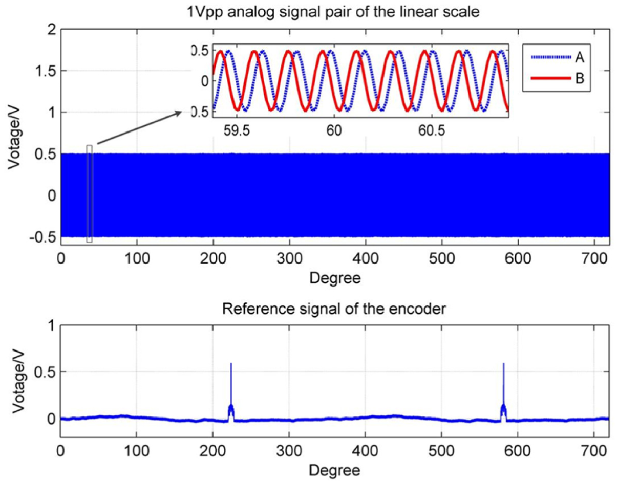
Analog signal pair of the linear scale and the reference signal of the encoder.
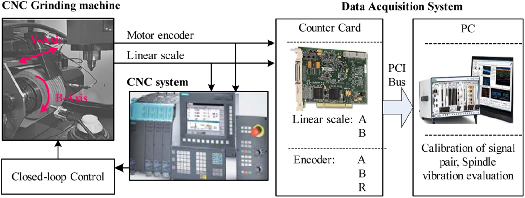
The flow chart for PFICG acquisition.
Experimental setup
The proposed methodology is employed for field spindle system balance of a high-precision CNC gear grinding machine, and the experimental system is shown in Figure 7. This grinding machine works in the generating grinding method, the work principle of which is the same as the hobbing machine. Three translational axes (X, Y, and Z-axis) and two rotary axes (B and C-axis) are employed in this machine, and the two rotary axes are both driven by servomotor without any decelerating mechanism. The spindle (B-axis) consists of a grinding wheel and a motor rotor which is supported by four angular contact ball bearings. A balancing disk at the end of the grinding wheel can be used for trial mass and correction mass adding. During the grinding process, the workpiece is carried by a rotary table (C-axis), and the grinding wheel is mounted on a spindle (B-axis) carried by three translation axes (X, Y, and Z-axis). The worm wheel and the workpiece rotate synchronously at a predetermined speed ratio which equals to Ng/Nw, where Ng is the tooth number of workpiece and Nw is the worm start of the worm wheel. An optical incremental rotary encoder with 2500 divisions per revolution is embedded in the spindle servomotor for the speed feedback. An optical incremental linear scale is mounted in the Y-axis guideway for the position feedback, in which the grating pitch is 5 µm.
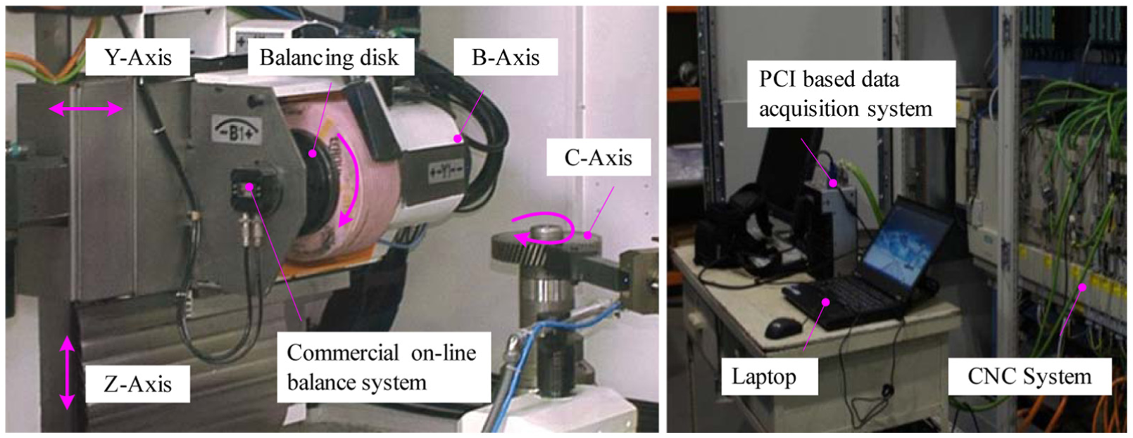
Experimental system.
In order to obtain the spindle vibration information under each condition (original vibration, trial mass, and residual vibration), a PCI-based data acquisition system is used in this experiment. In each condition, the Y-axis PFICG and key phase signal given by the encoder of spindle servomotor are captured synchronously by counter card and then transmitted to a PC for data storage and signal processing. Besides, to evaluate the effectiveness of proposed method, spindle vibration acceleration in horizontal, vertical, and axial directions is also monitored by the synchronous sampling device. For each condition, three data samples are collected with sampling frequency 2000 Hz.
Spindle balancing of a high-precision CNC grinding machine
Since this grinding machine often works when the spindle speed is 3000 r/min, in this experiment, the vibration when spindle runs at 4000 r/min is set as the objective balancing speed. According to the procedures introduced in section “Proposed sensorless balance method,” the details of the proposed balance method are implemented as follows:
The spindle is run up to 4000 r/min to get the original imbalance vibration data. Y-axis PFICG and key phase signal giving by spindle servomotor encoder are captured synchronously by counter card, and the key phase signal given by spindle servomotor encoder is used for sampling triggering. Figure 8 shows the PFICG of the original vibration, and the amplitude and phase angle of rotation frequency are 0.051 µm and ∠2.02°, respectively.
A trial mass (1.5 g at ∠0° in balancing disk) is added in the balancing disk to get trial mass data. Under this condition, Y-axis PFICG and key phase signal given by spindle servomotor encoder are also captured synchronously by counter card. Figure 9 shows the PFICG of the trial mass, and the amplitude and phase angle of rotation frequency are 0.097 µm and ∠4.88°, respectively.
The spindle vibration when spindle runs at 4000 r/min is set as the objective balancing speed, and the ICM is introduced for influence coefficient calculation. Using the data obtained from above procedures, the correction mass is calculated, and the amplitude and phase angle of rotation frequency are 2.3 g and ∠173.0°, respectively.
The correction mass is added on balancing disk for spindle vibration suppression. Figure 10 shows the PFICG of the residual vibration after balancing (its amplitude and phase angle are 0.012 µm and ∠188.70°), which illustrates the effectiveness of the proposed method.
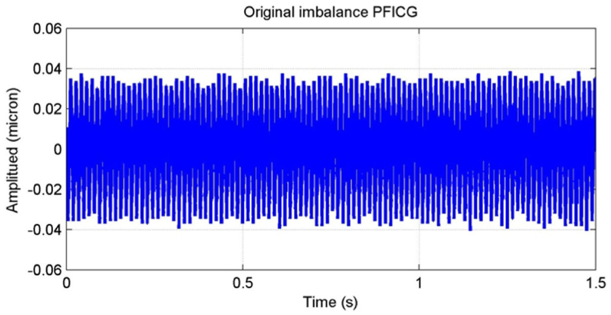
PFICG of the original vibration.
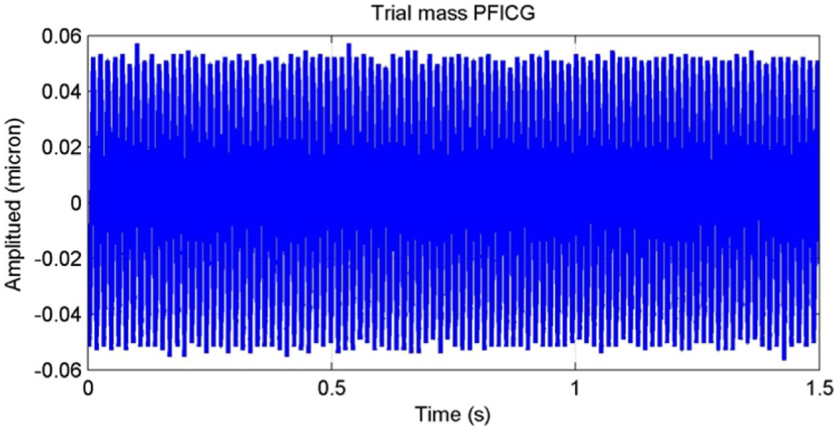
PFICG of the trial mass.
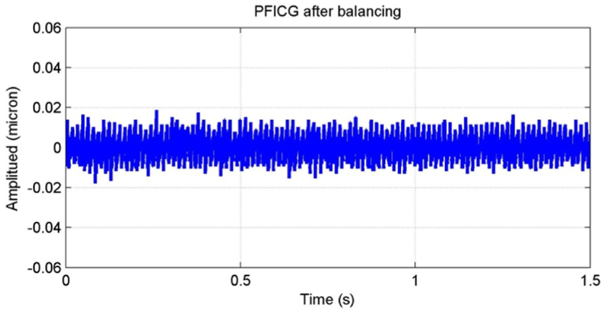
PFICG of the residual vibration.
To illustrate the effectiveness of the proposed balance method, the commonly used commercial balance system (SBS 4500 balance system) is also introduced for spindle vibration suppression. When the SBS 4500 balance system is employed, the horizontal direction vibration of the spindle is obtained as the reference information for the correction mass calculation, and the vibration acceleration is measured by accelerometers. At the same time, the objective balancing speed is the same as the one of proposed method. Table 1 shows the original vibration, residual vibration at the objective balancing speed after balanced by proposed method, and the SBS 4500 balance system.
Spindle vibration acceleration after balanced by different methods.
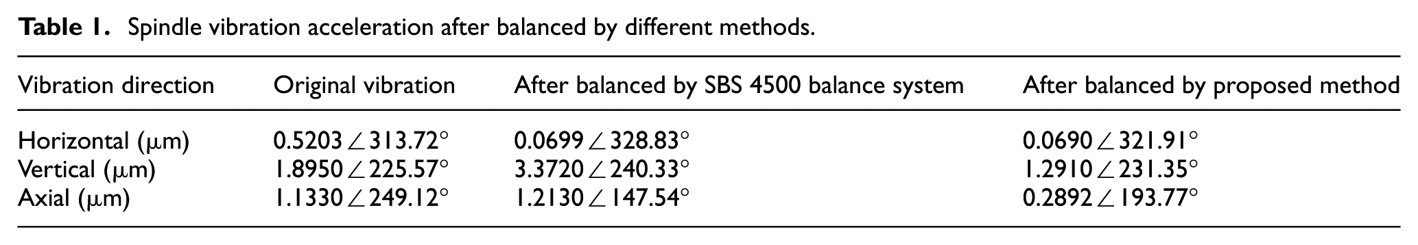
It can be seen from Table 1 that the imbalance vibration presenting in horizontal, vertical, and axial directions of the spindle can be suppressed simultaneously and effectively by proposed method. However, although the spindle vibration in horizontal direction can be suppressed effectively using the SBS 4500 balance system, it is not able to simultaneously reduce the residual vibration in horizontal, vertical, and axial directions. Indeed, the vibration amplitude is dramatically increasing in vertical and axial directions.
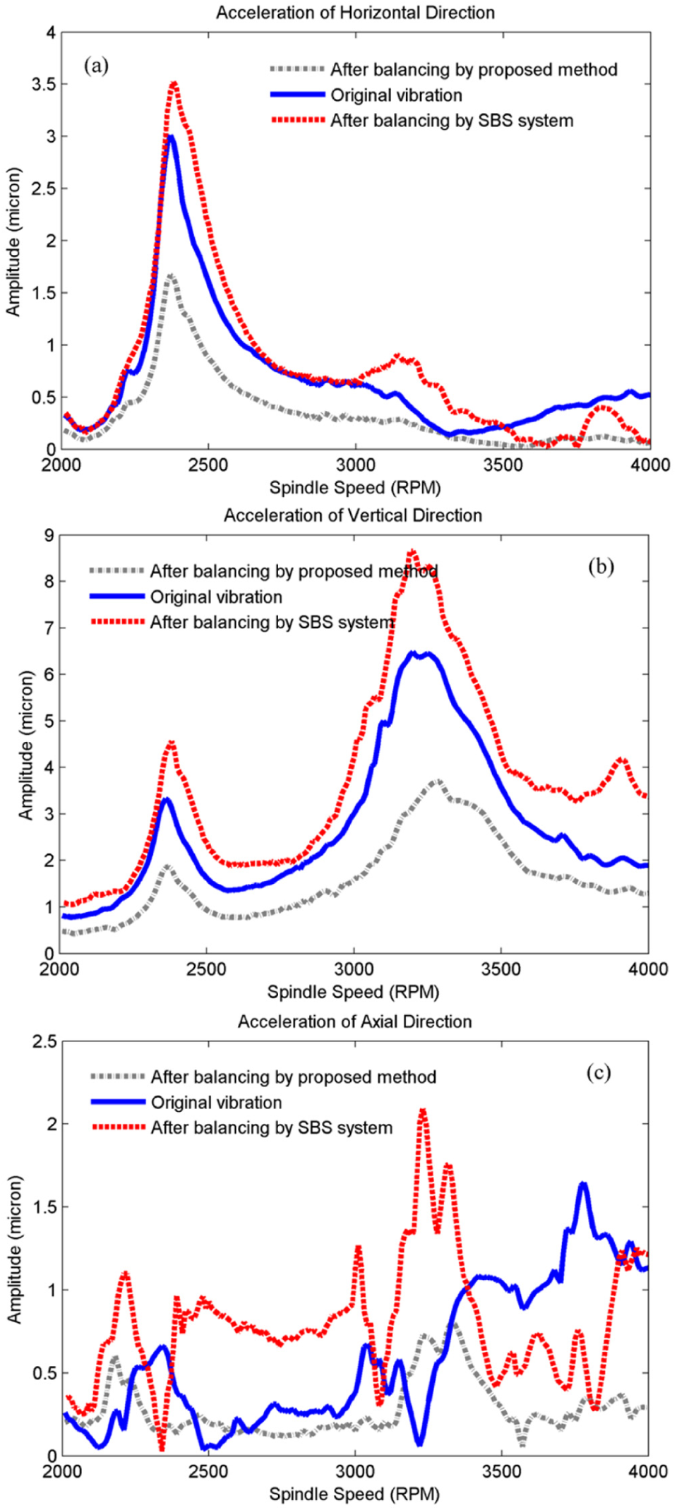
Moreover, the original vibration and residual vibration during the run-down process at the operating range from 2000 to 4000 r/min are also measured, respectively. Figure 11 shows the original vibration and residual vibration after balanced by proposed method and SBS 4500 balance system during the run-down process. It can be found from Figure 11 that:
As shown in Figure 11(a), after balanced by the SBS 4500 balance system, the residual vibration amplitude in reference direction (horizontal) is reduced effectively at the objective balancing speed (4000 r/min). But in vertical and axial directions, the residual vibration amplitude dramatically increases at the objective balancing speed, as shown in Figure 11(b) and (c).
The proposed balancing method can reduce the residual vibration in horizontal, vertical, and axial directions of the spindle simultaneously and effectively during the whole run-down process, as shown in Figure 11(a)–(c).
Although the commercial balance system can reduce the residual vibration in reference direction at the objective balancing speed, however, at some other speed of the run-down process, the residual vibration amplitude dramatically increases in horizontal, vertical, and axial directions compared with the original vibration.
After balanced at the objective balancing speed, the proposed balancing method can reduce the residual vibration amplitude more than 50% simultaneously in each direction during the whole run-up process. At the same time, the residual vibration amplitude in reference direction is suppressed below 1 µm during the whole run-down process.
Spindle vibration during the run-down process.
Conclusion
A sensorless balancing method is proposed for spindle system vibration suppression using the servo-axis PFICG of CNC gear grinding machine. Compared with the commonly used commercial balancing systems, the PFICG used in proposed method can be considered as an integrated representation of the spindle vibration. Therefore, from the theoretical aspect, the spindle vibration presenting in horizontal, vertical, and axial directions can be suppressed simultaneously by proposed method. A field experiment is carried out in a high-precision CNC gear grinding machine. At the same time, to illustrate the effectiveness of the proposed balance method, the commonly used commercial balance system (SBS 4500 balance system) is also introduced for spindle vibration suppression. Experimental results showed that, compared with the SBS 4500 balance system, the spindle vibration in horizontal direction at the objective balanced speed (4000 r/min) decreases more than 85% after balancing using the proposed method, and the vibration in vertical and axial direction decrease more than 50% of the original vibration in the whole run-down process. Potentially, this PFICG-based balance method provides an alternative solution for spindle system vibration control of the CNC gear grinding machine.
Footnotes
Declaration of conflicting interests
The author(s) declared no potential conflicts of interest with respect to the research, authorship, and/or publication of this article.
Funding
The work was supported by the National Natural Science Foundation of China (No. 51505147), the China Postdoctoral Science Foundation Project (No. 2015M581545), and partly supported by the Fundamental Research Funds for the Central Universities (No. 222201514315), which is highly appreciated by the authors.