
Abstract
The differences in the cutting speed are a serious problem along the cutting edge of the drill, in drilling operations. This problem can partly be solved reducing the length of the cutting edge via changing the drill point angle. In addition, in this study, the effect of point angle, feed rate, and cutting speed on drilling is investigated. For identifying the optimum cutting parameters, AISI 1050 steel alloy was selected as the experimental specimen, these specimen were pre-drilled 5 mm in diameter due to eliminating the effect of the chisel edge. In the experiments, the holes were drilled only at a depth of 10 mm in order not to give any harm to the dynamometer while measuring thrust force. For this aim, in drilling process, drills with point angle of 100°, 118°, 136°, 154°, and 172° were selected. In conclusion, the thrust force, the tool wear, and the surface roughness linearly decreased with increasing point angles due to less removal chip area, in per revolve of the tool. However, the thrust force, the tool wear, and the surface roughness were adversely affected at higher feed rates and lower cutting speeds. The hole dimensional accuracy decreased at lower feed rates and cutting speeds but at higher point angles and concurrently at higher feed rates but lower point angles and cutting speeds. However, the hole dimensional accuracy showed more decisiveness at 118° than other point angles, while the highest dimensional accuracy values recorded at 136° point angle, at higher cutting speeds.
Introduction
Drilling is a manufacturing process that provides desirable geometrical and dimensional accuracy in the product of machine parts, also for installation processes, as well. 1 It is including approximately 33% of all metal cutting operations. Despite the importance of the drilling operations, there are many factors, such as drill point angle, the characteristics of drill materials and workpiece have effects on machining processes. 2
While increases in feed rate forms the rough surface of the drilled hole, higher spindle speeds, and point angles produce better surface finish due to the reduced thrust force and in this way by providing the minimum tool wear.3,4 The number of the drilled holes is the most considerable factor affecting the wear rate, as well. 5 The thrust force, decreasing with increases in both the point and helix angles, in drilling operations, is an important parameter to affect the results, such as surface roughness, hole diameter deviation, and burr height.6,7
The parameters providing the longer tool life and less tool wear are acceptable as optimum for the selected machining operation. An increase in both chisel edge length and feed rate causes increase in the thrust force, but a pilot pre-drilled hole can reduce the thrust force by about 25%–50%, which is more than the critical value in thrust force reduction (maximum 11%). 8 But at the chisel edge, where the cutting speed goes toward zero, the forces at the chisel edge can be neglected. 9 Due to feed rate affects the thrust force, it is more associated with parameter in influencing the quality characteristics of the drilling processes and affecting the drilling forces rather than the cutting speed. 10
The geometry of the tip of the drill is a component in determining its performance and characteristics. A minimization of thrust force and torque leads to an improvement of drill performance by reducing drill deflections and lowering the power required during the drilling processes.11,12
Surface roughness is an important outcome in drilling operations, as well as in machining. With increasing the spindle speed, the surface roughness of the drilled hole decreases, but it increases with increasing feed rate. 13
The shape of the removed chip may be the best indicator of the quality of a machining operation. The better performances, such as desirable chip formation, can be gained at the lowest cutting speed and feed rates in drilling operations.3,14 Discontinuous plastic deformation leads to the fan-shaped and breakup removal chips, in the cutting zone, at lower spindle speed during the drilling operations. However, at medium spindle speeds, the breakup chips, and sequential short helical chip forms are converted into long helical chips. 3 The chip thickness is highly variable along the length of the cutting edge and during the tool revolution in the workpiece. 15 Therefore, the form of the chip structure changes from ductile to brittle with increasing cutting parameters. Furthermore, with increasing feed rate, the burr height decreases, but thrust force, the deviation of the hole, the surface roughness, and the tool wear increase. 6 However, at selected low cutting speed and feed rate, but higher point angles, minimum chip height is gained. 16
The main problem in drilling operations is a variety of cutting speed along the length of the cutting edge of the drill. The tapered shape of the drill, starting from the tip of the drill to its outer circle, causes the variation in cutting force, thoroughly with the cutting edge of the drill material. 17 This taper angle is comprised by the point angle. The main reason for the problems in drilling operations is the variation in cutting speed along the cutting edge of the drill. While the cutting speed is maximum at the periphery of the outer diameter of the drill, which generates the cylindrical surface, and it approaches zero near the center line of the drill, where the cutting edge blends to a chisel shape. 18
The variation in cutting speed, throughout the cutting edge of the drill, is the major problem that leads to poor surface quality, severe tool wear, and shorter tool life in drilling operations. Although 118° drill point angle is preferred in drilling of steel materials, this problem has been in progress due to point angle is a vital identifier for the length of the cutting edge. Therefore, the main goal of this paper, diversified from the literature, is to investigate the effects of the point angle on the length of the cutting edge and namely on the drilling process, with selecting point angles in a wide range, between 100°–172°. Furthermore, in drilling operations, applied with drills, having bigger point angles, higher feed rates cannot be selected, due to inadequacy in length of the cutting edge. Especially, for identifying this inadequacy limits, lower feed rates, and higher point angles, in wide range were selected. Moreover, the outcomes such as the thrust force, the shape of the chip, surface roughness, tool wear, and the delamination of the drilled holes are analyzed according to the point angle and especially the length of the cutting edge. Because, at higher point angles, the removal chip area, in per revolution of the tool in the workpiece, decreases, which provides a better surface quality, small thrust force, less tool wear, and longer tool life. The samples were pre-drilled 5 mm in diameter in an attempt to eliminate the effect of the chisel edge. In this way, we can investigate the effects of point angle; accordingly, the length of the cutting edge on the drilling performance, according to the processes outcomes, such as thrust force, surface roughness, drilled holes dimensional accuracy, tool wear, and chip formation.
Material and methods
Experimental setup and drilling conditions
The drilling experiments performed on MEXUS 510 C-II Model Mazak Vertical Center CNC Milling machine, shown in Figure 1(a). The AISI 1050 alloy samples were prepared in dimensions of 100 × 100 × 15 mm. The holes were pre-drilled 5 mm in diameter as pilot holes. The separation distance between the centers of the holes was adjusted as 20 mm, but the first hole center 10 mm from the corner of the material. During drilling operations, the thrust forces, the direction drill, and proceeding into the workpiece were recorded in Newton unit, via Kistler 5233A dynamometer, as shown in Figure 1(b). The datum, which was gained from the data logger, was saved by the help of a computer, as seen in Figure 1(c).
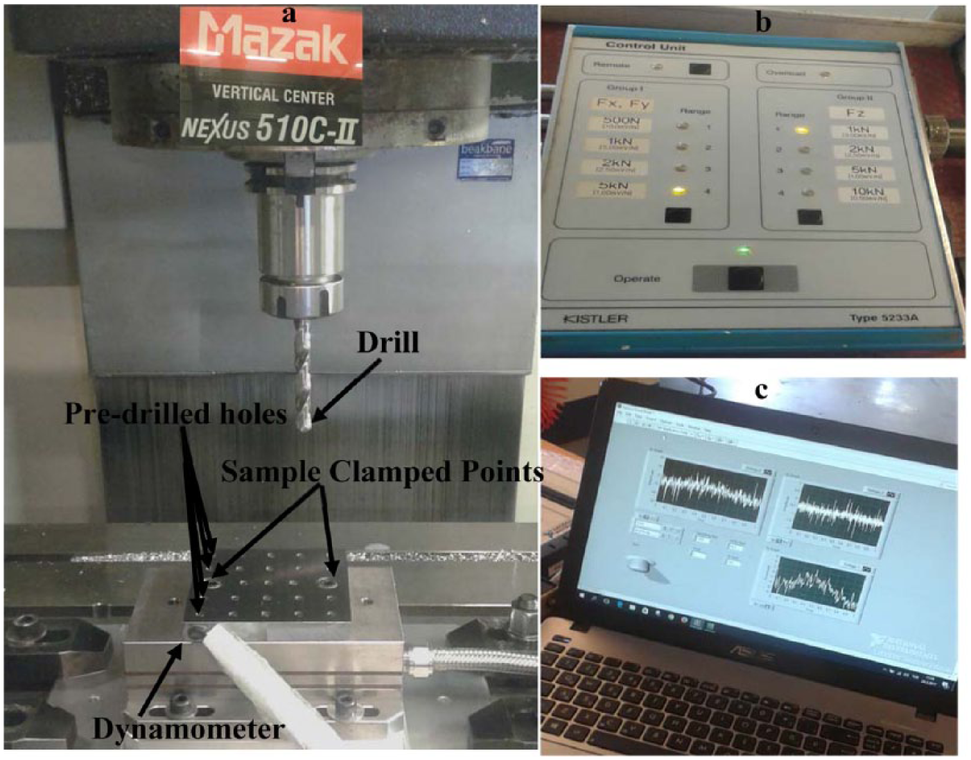
Experimental setup: (a) CNC milling machine, (b) 5233A Type dynamometer, and (c) computer.
The hole dimensional accuracy was measured by using a micrometer, in four different directions and 5 mm in depth from the entry of the hole, as shown in Figure 2. These dimensional accuracy values can be compared and evaluated according to the selected parameters, such as cutting edge length and thrust forces. Thrust force values recorded by means of 5233A type dynamometer data logger in the direction of Z-axis, in which the drill was progressed into the workpiece.
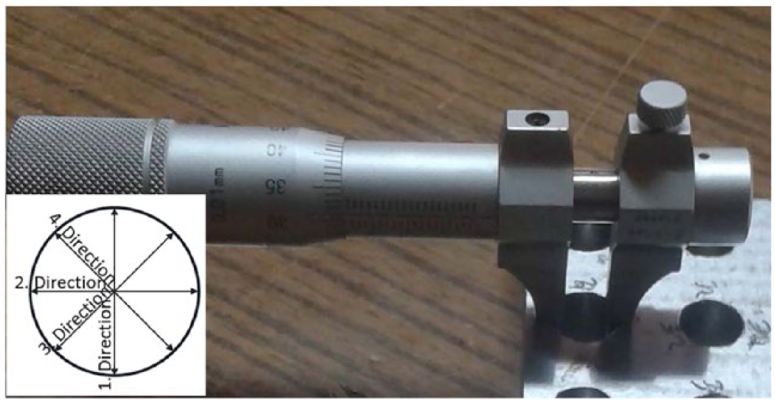
Measurement of the drilled holes in diameters at four different directions by using inner diameter micrometer.
AISI 1050 steel alloy samples were pre-drilled 5 mm in diameter and 13 mm in depth, in cooling condition, at 50.27 m/min cutting speed and 0.1 mm/rev feed rate. After holes had been pre-drilled, as pilot holes, they were drilled 10 mm in depth from the top face of the samples by using the selected parameters, as shown in Table 1.
Drilling experiments parameters and drill tool geometrical properties.
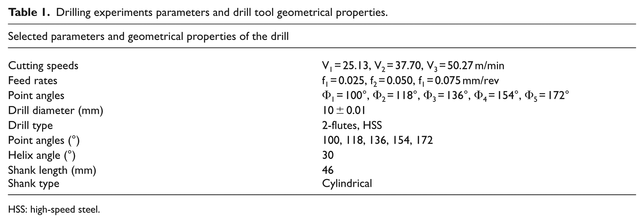
HSS: high-speed steel.
The drill surfaces, cutting edge, chips, and flute faces of the drills were also analyzed by metallographic studies. A Stereo, LEICA Z16 APO model microscope was used for this purpose. The surface roughness of the drilled holes measured by using TR 200 TIME SIRF surface roughness device at a sampling of 0.8 mm.
Geometrical properties of drills and their preparation procedures
The effects of point angle on the results were investigated in this experimental paper. Therefore, five different point angles were selected as 100°, 118°, 136°, 154°, and 172°. The drills, 10 mm in diameter, were provided. Then they were ground, at the selected point angles degrees, on the grinder machine. The selected parameters and the geometrical properties of the drills can be seen in Table 1. Drills were clamped to the spindle of CNC machine by the help of the connecting apparatus, as all of the shanks of the drill were grasped by the connecting apparatus.
Calculation of cutting edge length according to the point angle
Throughout the length of the cutting edge of the drill, the cutting speed has variation values. While at the periphery of the drill, cutting speed has a maximum value, toward the center line of the drill, where the web of the drill is placed, and cutting edge is blended to the chisel edge, this value approaches zero. 18 Therefore, the point angle of the drill has a significant effect on drilling because of the length of the cutting edge of drills having an alteration with changing the point angle of the drills. In Figure 3, the geometrical modeling of the cutting edge of a drill can be seen.
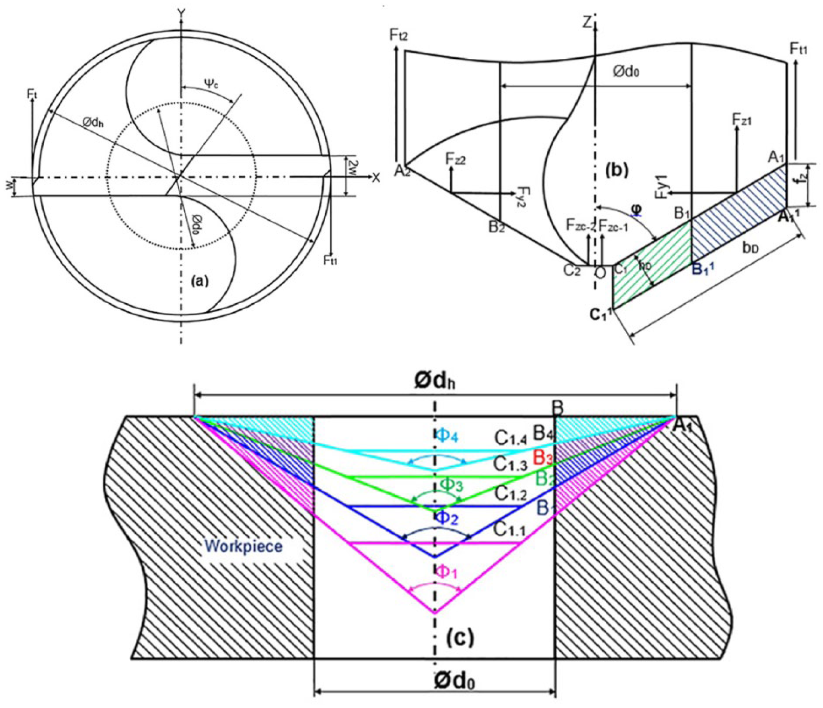
(a) The top view of the drill point, (b) the front view of the drill point, and (c) the geometrical modeling of the cutting edge of the drill 18 .
In Figure 3(a), Ødo is the symbol of pre-drilled pilot hole diameter, and Ødh is a symbol of the drill diameter. The length of the chisel edge is 2w, Ft1 and Ft2 are the tangential forces, and Fz1 and Fz2 are the thrust forces on the first and second cutting edge of the drill, respectively. Fy1 and Fy2 are the radial forces in the direction of revolving of the drill. Fzc–1 and Fzc–2 are the thrust forces on the chisel edge. ψc is the chisel edge angle. Φ is the half value of the point angle and equal to Φ/2 (Φ1, Φ2, Φ3, Φ4 are 100°, 118°, 136°, 154°, respectively).
If the samples were not pre-drilled the length of the cutting edges would be |C1.1–A1|, |C1.2–A1|, |C1.3–A1|, and |C1.4–A1| for 100°, 118°, 136°, and 154° point angles, respectively. But in this study, we pre-drilled samples 5 mm in diameter to eliminate the effect of the chisel edge. Accordingly, the cutting-edge length of the drills, used in this experimental study, were |B1–A1|, |B2–A1|, |B3–A1|, and |B4–A1| for 100°, 118°, 136°, and 154° point angles, respectively.
In experiments, five different kinds of point angle values were selected, as 100°, 118°, 136°, 154°, and 172°. However, the drilling processes planned to be performed as a part of this experimental study would be performed by using the drill, having 172° point angle and could be failed to satisfy due to the projection height of the cutting edge on the Z-axis was too small. Since this projection height was small, the tool to be proceeded into the workpiece by cutting according to the feed rate (fz) values, the drill deformed the workpiece instead of drilling it by cutting. We could try only one sample to drill 1–2 s. In this experiment, as soon as the tip of the drill, which has 172° point angle, touched the workpiece, both the thrust and torque forces values were abruptly elevated to stiff values in a very short time (1–2 s). Thus 172° point angle parameter was eliminated for this experimental study.
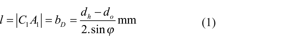
In this experimental study, the samples were pre-drilled 5 mm in diameter (Ødo) to eliminate the effects of the chisel edge. For drilling samples, which were not pre-drilled, the undeformed chip width namely the length of cutting-edge length could be calculated geometrically by using equation (1), according to Figure 3(b)
The thickness of the undeformed chip (hD) can be calculated geometrically depending on the feed rate (fz) and one-half point angle (φ), by using equation (2), according to the geometrical shape, as seen in Figure 3(b)

In Figure 3(b), the area of |C1C1 1 –A1A1 1 | rectangle represents the undeformed chip in drilling processes, in which the samples are not pre-drilled. This can be calculated depending on the depth (hD) and width of the chip (bD), as shown in equation (3). (hD) which is the chip thickness per flute in one revolution of the drill

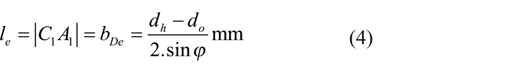
In this experimental study, the samples were pre-drilled 5 mm (Ødo) in diameter, as a pilot hole. Hence, in pre-drilling conditions, the length of the cutting edge, namely the width of the undeformed chip and the undeformed chip thickness are indicated as (bDe) and (hDe), respectively. The undeformed thickness of chip (bDe), gained in without pre-drilling processes, is equal to the undeformed thickness of the chip (hDe), gained in pre-drilled drilling operations, as shown in equation (2). However, the undeformed chip width, without pre-drilled drilling processes, is different from the undeformed chip width, in pre-drilled drilling operations, due to the diameter (Ødo) of the pre-drilled hole. It is represented in equation (4)
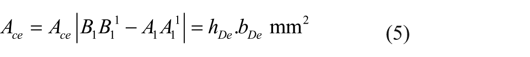
Under the circumstances, the effect of the undeformed chip (Ae) can be calculated depending on the undeformed chip width (bDe) and the undeformed chip thickness (hDe), shown in equation (5)
In this experimental study, there are five different kinds of point angles (Φ1, Φ2, Φ3, Φ4, and Φ5) which are definite, as seen in Figure 3(c). For realized experiments, point angles were selected, as 100°, 118°, 136°, 154°, and 172°, respectively. According to the geometrical shape of the point of the drill, the variation of cutting edge lengths (l) and (le), namely undeformed chip widths (bD) and (bDe), was changed with the variation of point angles.
In conditions, samples are not pre-drilled, the length of the cutting edge, namely the width of the undeformed chip is changed from 5.222 to 4.010 mm, with changing point angle from 100° to 172°, according to the equation (1). In conditions, samples pre-drilled 5 mm (Ødo) in diameter the effective cutting-edge length, namely the effective undeformed chip width changed from 3.264 to 2.51 mm, with changing the point angle from 100° to 172°, according to the equation (4). Considering that the cutting-edge length changed; therefore, the area of undeformed chip changes too.
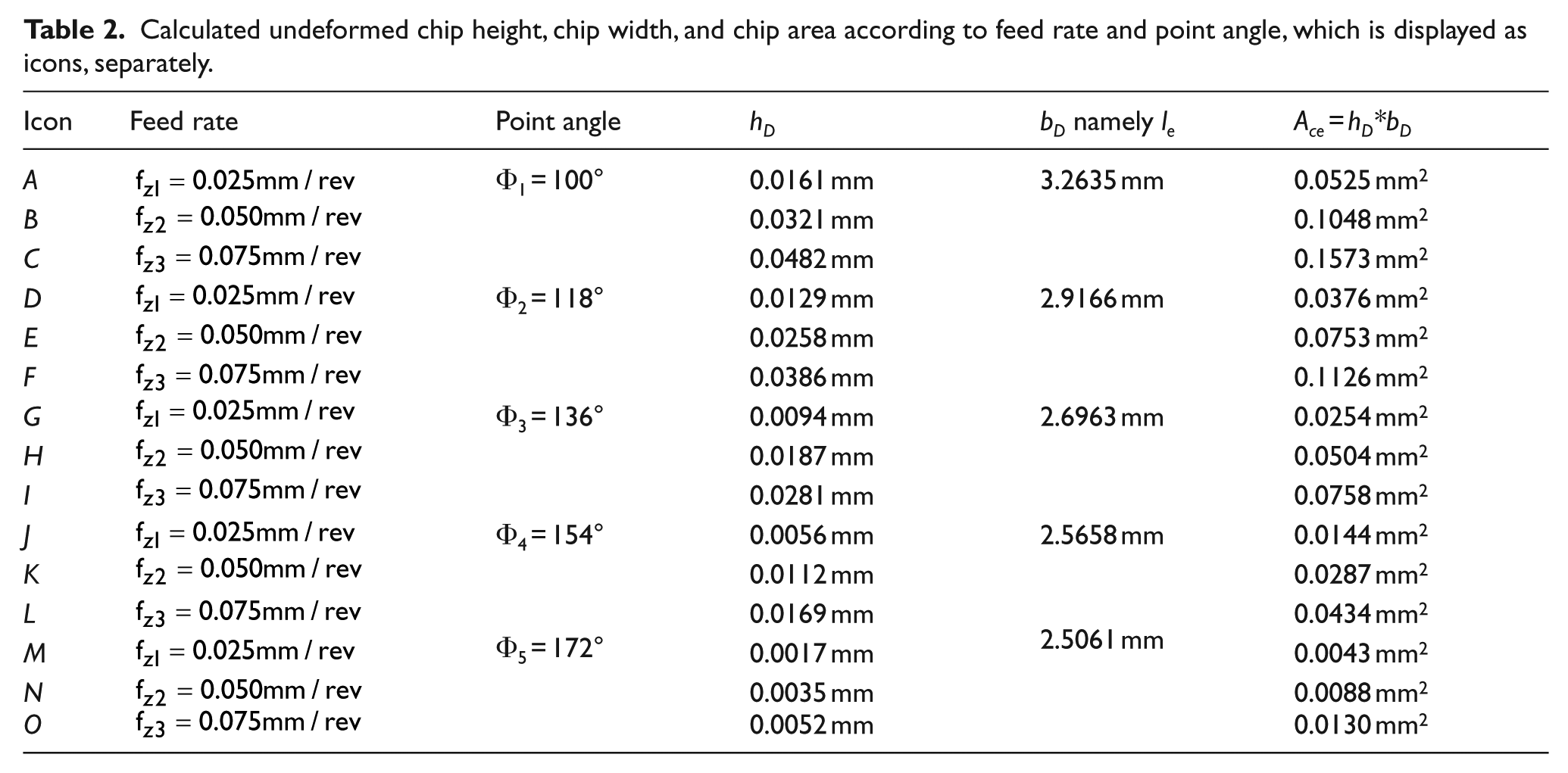
The area of the undeformed chip in drilling operations substantially depends on the cutting-edge length, namely undeformed chip width. According to the equations (2), (4), and (5), the effective undeformed chip height (hD), the tool cutting-edge length (le) namely undeformed chip width (bD), and thereby, undeformed chip area (Ace) can calculate relative to feed rate and drill tool point angle. Depending on the geometrical shape of the drill tip, the undeformed chip height is only related to both feed rate (fz) of one cutting edge at per revolution and point angle of the drill. The length of the drill cutting edge namely undeformed chip width depends on both drill diameter and point angle. On that account, both feed rate and point angle parameters couples are displayed as icons: A, B, C, D, E, F, G, H, I, J, K, L, M, N, and O, as seen in Table 2. In drilling operation, the thrust force surged abruptly to 1400 N; therefore, drilling operation was terminated. For this reason, in Figure 5, the thrust force values was gained from drilling operations by using the drill, whose point angle was 172°, are not shown.
Calculated undeformed chip height, chip width, and chip area according to feed rate and point angle, which is displayed as icons, separately.
Results and discussion
The cutting forces have important effects on tool life and surface quality, also its magnitude depends on the cutting tool geometry; tool material; the properties of the machined samples; and machining parameters like cutting speed, feed rate, and undeformed chip thickness. In drilling operations, because of the geometry of the drills, especially the point angle of the drill, providing the cutting edge a taper angle, the cutting speed has a variation along the cutting edge. A decrease in point angle leads to increase the length of the cutting edge, thus the variation along the cutting edge increases. Moreover, the increase in point angle provides the reduction in the undeformed chip height and width; consequently the undeformed chip area and in this way in cutting forces, especially in thrust force (fz), in drilling operations.
Thrust forces in drilling operations
In the direction of drill proceeding, namely in the direction of Z-axis, some pictures of the measured thrust force values are shown in Figure 4, according to the selected parameters. The recorded values show a uniform rising with the cutting tool proceeding into the workpiece, at low feed rates, point angles, and cutting speed, as shown in Figure 5. At 0.025 mm/rev and 25.13 m/min, an increase in point angle caused relatively less fluctuation in thrust force. This reduction in the fluctuation in thrust force was considered as in the taper angle of the tip of the drill because of increases in the point angle. As taper angle reduced, the torque of the drill decreased due to the shortness of the cutting edge, but when it increased the thrust forces increased collaterally with changing the diameter from 0 to 10 mm. At 0.025 mm/rev and 50.27 m/min, a sudden increase in thrust force was observed during the first contact on some of the specimen because of the static friction force. Higher fluctuation in thrust force was observed with increasing point angle. However, the fluctuation in thrust force decreased at lower feed rate (0.025 mm/rev), higher cutting speed (50.27 m/min), and point angle (154°). At the first contact, carried out between the drill tool and the workpiece, a sudden increase in thrust force was also observed at 154° point angle, but thrust force variation decreased and showed better stabilization at the rest of the operations.
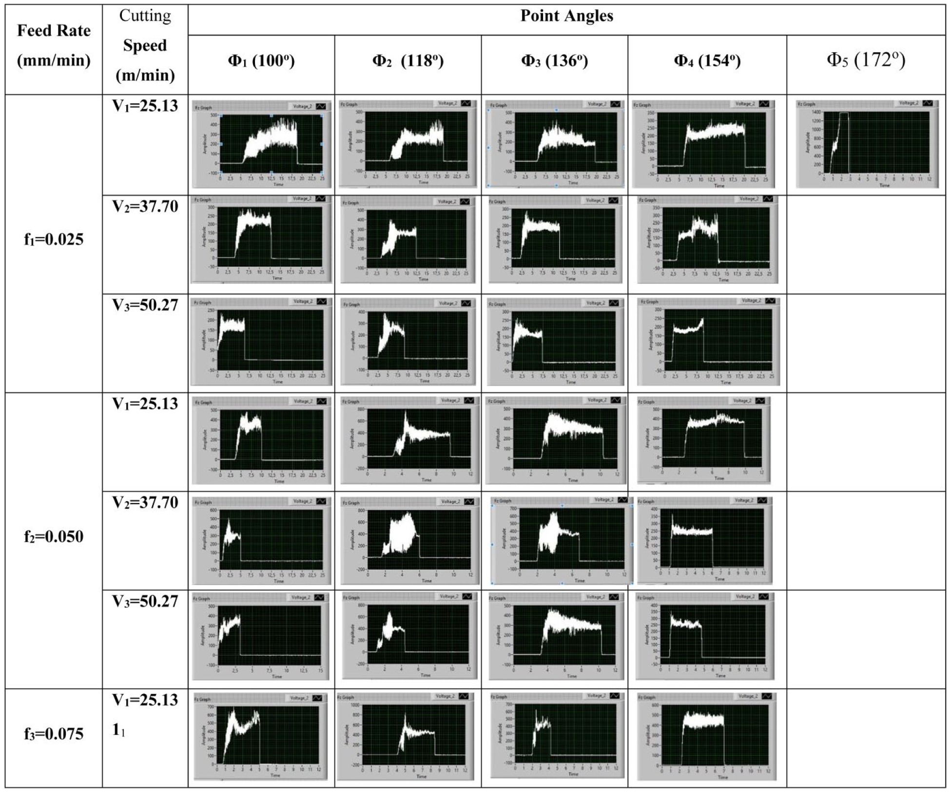
The thrust forces, in the drilling of AISI 1050 by using different drills, having different point angles.
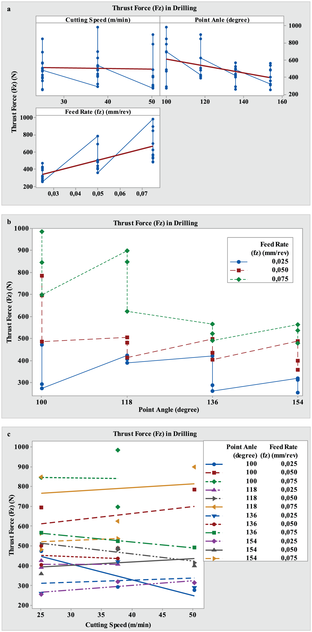
The variations of thrust forces in drilling of AISI 1050. The effect of a) all selected parameters, b) the point angle in details, c) the cutting speed in details, on the alterations of the thrust force in drilling.
According to the recorded thrust force results, 0.075 mm/rev feed rate is not suitable for 100° point angle at 25.13 m/min cutting speed, because of higher forces variation. Better results were observed at 118° point angle and when the first contact was carried out between the tool and the workpiece. However, the thrust force fluctuation is very high at 118° point angle. At 136° point angle, the gained thrust force results are acceptable. An increment in cutting speed provides less thrust force, which is more desirable in drilling operations as seen in Figure 5. The undeformed chip thickness and width are decreased because of the amount of the chip, which was removed in per revolution of the drill and chip geometrical sizes. In addition, an increment in point angle led to the reduction in thrust force in the same way. According to the Figure 5, the thrust force changed with changing the cutting speed. Moreover, in different point angles and feed rates, the thrust forces decreased linearly.
Only the maximum measured thrust force value is taken into account for every experiment, separately. As shown in Figure 5, only the graph of the maximum thrust force values were taken into account. Thrust force values decreased with increasing both the cutting speed and point angle but naturally increased with increasing feed rate, in drilling operations, in which samples were pre-drilled 5 mm in diameter and 13 mm in depth.
In Figure 5(b), thrust force values variation are examined according to the point angle of the drill tool, namely cutting tool edge width (bD) and undeformed chip thickness (hD). The undeformed chip thickness depended on both the drill point angle and the feed rate, while the undeformed chip width, namely cutting tool edge length depended on the drill diameter and the drill point angle. The icons from A to L, shown in Table 2, define the effect of the undeformed chip thickness, width, and consequently the undeformed chip area on the thrust force in pre-drilled drilling operations.
According to the Figure 5(b), at all selected feed rates, the thrust force decreased, regularly, with changing the drill point angle from 100° to 154°. However, at every feed rate condition, the thrust force was shown discrepancy depending on the spindle speed, as shown in Figure 5(c). While the maximum thrust force value gained at 25.13 m/min cutting speed, at 0.075 mm/rev feed rate, and at 100° drill point angle, the minimum thrust force value was recorded at 50.27 m/min cutting speed and 154° drill point angle, measured as 985.04 and 253.51 N, respectively.
Tool wears in drilling operations
Tool wear, as seen in Figure 6, is affected by variations of parameters, such as feed rate, cutting speed namely spindle speed, drill point angle, tool material, and samples materials.
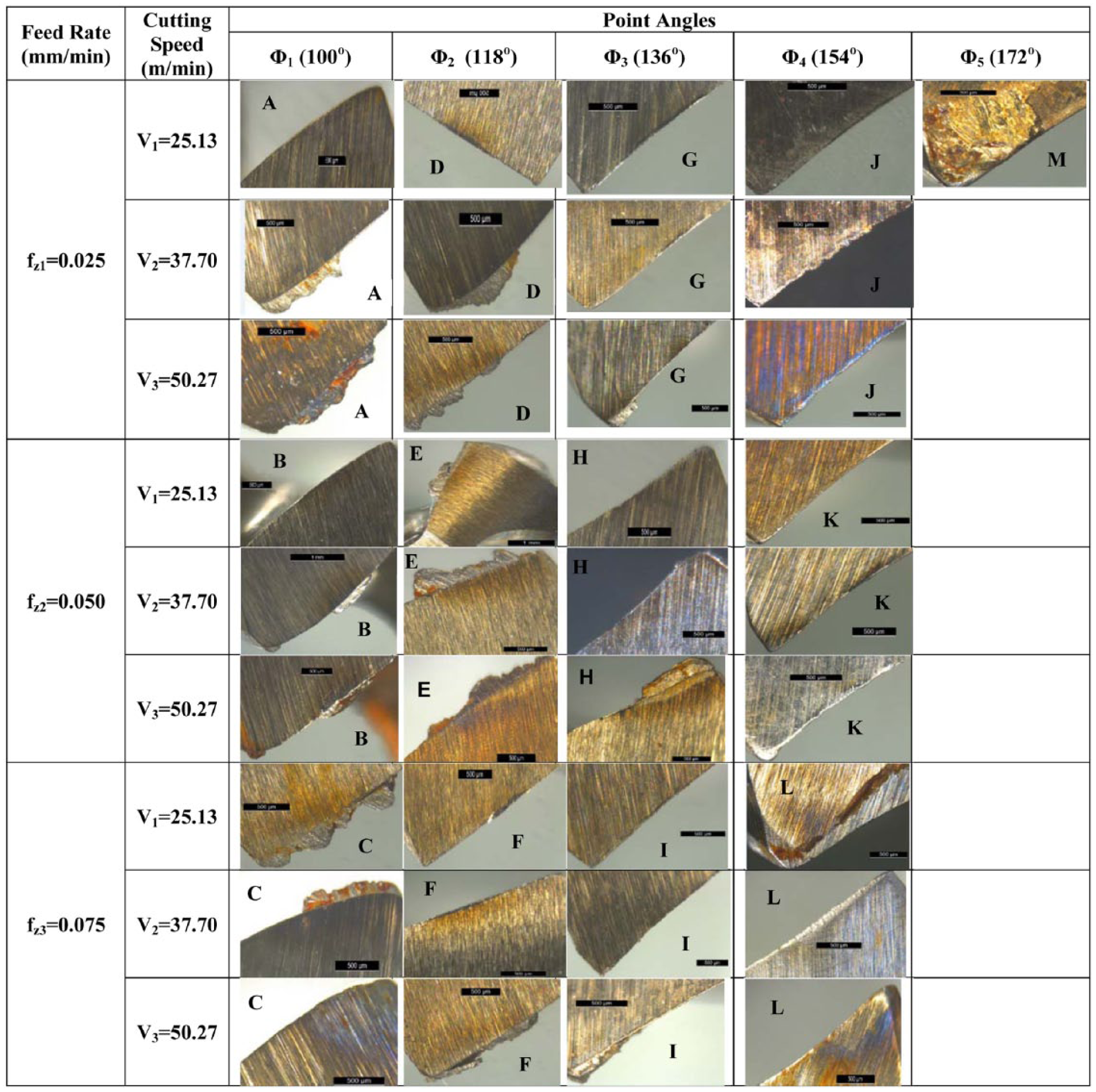
Drill wear according to the selected parameters (the measuring stick on the pictures show 500 µm).
An increment in both spindle speed and feed rate led to increase the process temperature, causing an adverse effect on the cutting edge such as quantity of wearing and burning scars. However, increase in point angle resulted in smaller cutting edge caused the reduction in chip sizes such as the undeformed chip thickness, the undeformed chip width, and the thrust force. Most of the tool wear and burning scars took place on the drill, at 100° point angle, while lower drill cutting edge damage and cause burning scars at 154° drill point angle. Drill cutting edge wear was shown collateral changing to the drill point angle, according to the feed rate and spindle speed parameters. Lower drill point angle had an unfavorable effect on the drill wearing, in other words, higher point angles provided less wearing on the drill cutting edge. However, the effect of the feed rate and the spindle speed on the wear of the drill cutting edge was collateral. High feed rates induced wearing of the drill because of the deformation effect, while spindle speed triggered the process temperature, which caused burning scars on the cutting edge, as seen in Figure 6.
Hole dimensional accuracy in drilling operations
The dimensional accuracy is a problem, the most desirable to solve, in drilling operations, due to influence on both the precision and accuracy in manufacturing machine samples. Therefore, as shown in Figure 7, in this paper, the dimensional accuracy of the drilled holes was investigated according to selected parameters. According to the graphs, shown in Figure 7(a), the dimensional accuracy increases collaterally with increasing feed rate, spindle speed, and drill point angle. The effect of the spindle speed and the point angle on the hole dimensional accuracy was more than the feed rate.
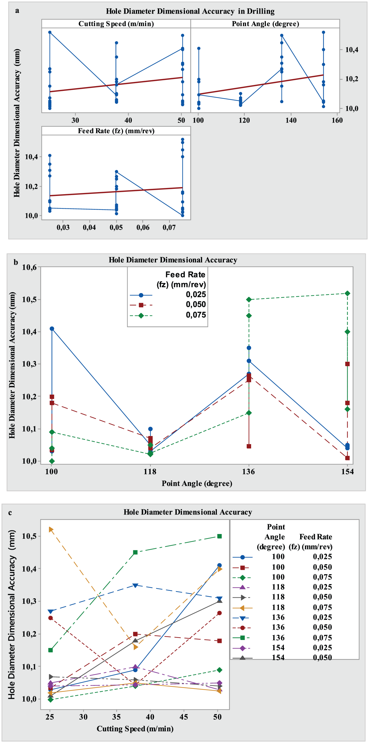
The quantity of dimensional accuracy in pre-drilled drilling of AISI 1050. The effect of a) all selected parameters, b) the point angle in details, c) the cutting speed in details, on the alterations of the hole diameter dimensional accuracy in drilling.
As seen in Figure 7(b), at all selected feed rates, the drilled holes dimensional accuracy showed a variation value with changing spindle speed from 25.13 to 50.27 m/min. At 0.025 mm/rev feed rate, the maximum dimensional accuracy values were gained at 100° and 136° point angles, while the minimum values were recorded at 118° and 154°. At 0.075 mm/rev feed rate, the hole dimensional accuracy increased at 136° and 154° drill point angles. However, at 0.050 mm/rev feed rate, the fluctuation of dimensional accuracy was less than the other selected feed rates for all selected spindle speeds. In Figure 6(c), the effect of all selected parameters on the drilled holes dimensional accuracy can be seen.
At 100° drill point angle, the dimensional accuracy showed an excessive augment at 0.025 mm/rev and 50.27 m/min cutting speed. However, the magnitude of the dimensional accuracy diminished with changing feed rate from 0.025 to 0.075 mm/rev and increasing the spindle speed from 25.13 cutting to 50.27 m/min. Nevertheless, the fluctuation of the dimensional accuracy diminished and showed more stability at 118° drill point angle than other point angles, and at all remained selected parameters. At 136° point angle, the lowest quantity of dimensional accuracy was achieved at 0.050 mm/rev feed rate and 37.70 m/min cutting speed, but a chang in feed rate and spindle speed caused increase in dimensional accuracy at this angle. It means that for 136° point angle, 0.050 mm/rev feed rate and 37.70 m/min cutting speed, parameters couple, investigated as the most appropriate results were achieved according to the drilled hole dimensional accuracy criterion. When the drill point angle increased to 154°, at 25.13 m/min spindle speed, 0.025 mm/rev, and 0.050 mm/rev feed rates, the hole dimensional accuracy decreased, but with increasing spindle speed to 50.27 m/min, the dimensional accuracy showed an increment. These results show that the increase in feed rate and spindle speed was favorable, namely for high feed rates, higher spindle speeds and for low feed rates, lower spindle speeds recommended to be selected. Besides, at 0.075 mm/rev feed rate, only 37.70 m/min cutting speed was an appropriate parameter according to dimensional accuracy criterion.
The minimum quantities of dimensional accuracy were measured at 0.025 mm/rev feed rate, 25.13 m/min spindle speed and 154° drill point angle as 0.00 mm, namely zero dimensional accuracy. About the same quantity of dimensional accuracy was gained at 136° point angle at the same feed rate and spindle speed, as 0.010 mm. At 118° point angle, 0.050 mm/rev feed rate, and 37.70 m/min cutting speed, the measured quantity of dimensional accuracy was 0.010 mm as well. The maximum dimensional accuracy values were recorded as 0.45 and 0.50 mm, respectively, at .075 mm/rev feed rate, at 136° point angle, at 1200 and 50.27 m/min cutting speeds, also at 0.075 mm/rev feed rate, at 154° point angle, and at 25.13 m/min spindle speed, as 0.52 mm. This result showed that increase in spindle speed causes an increase in hole dimensional accuracy at higher point angles. The dimensional accuracy, which was gained in conditions 172° point angle, 0.025 mm/rev feed rate and 25.13 m/min spindle speed was measured as 2.2 mm.
The pictures of drilled holes are given in Figure 8 according to selected parameters, such as feed rate, spindle speed, and drill point angle because the setting up of the dynamometer under the samples holes were not drilled all along the thickness of the samples. Thereby, they were drilled only 10 mm in depth. The length of all measurement sticks in the pictures is 1 mm. The chipping at the entry of the holes was increased with increasing feed rate and spindle speed, moreover, at 118° and 136° drill point angles, the chipping increased, as seen in Figure 8. In the circumstances, the minimum chipping took place at 0.075 mm/rev feed rate, 37.70 and 50.27 m/min cutting speeds, at 154° point angle.
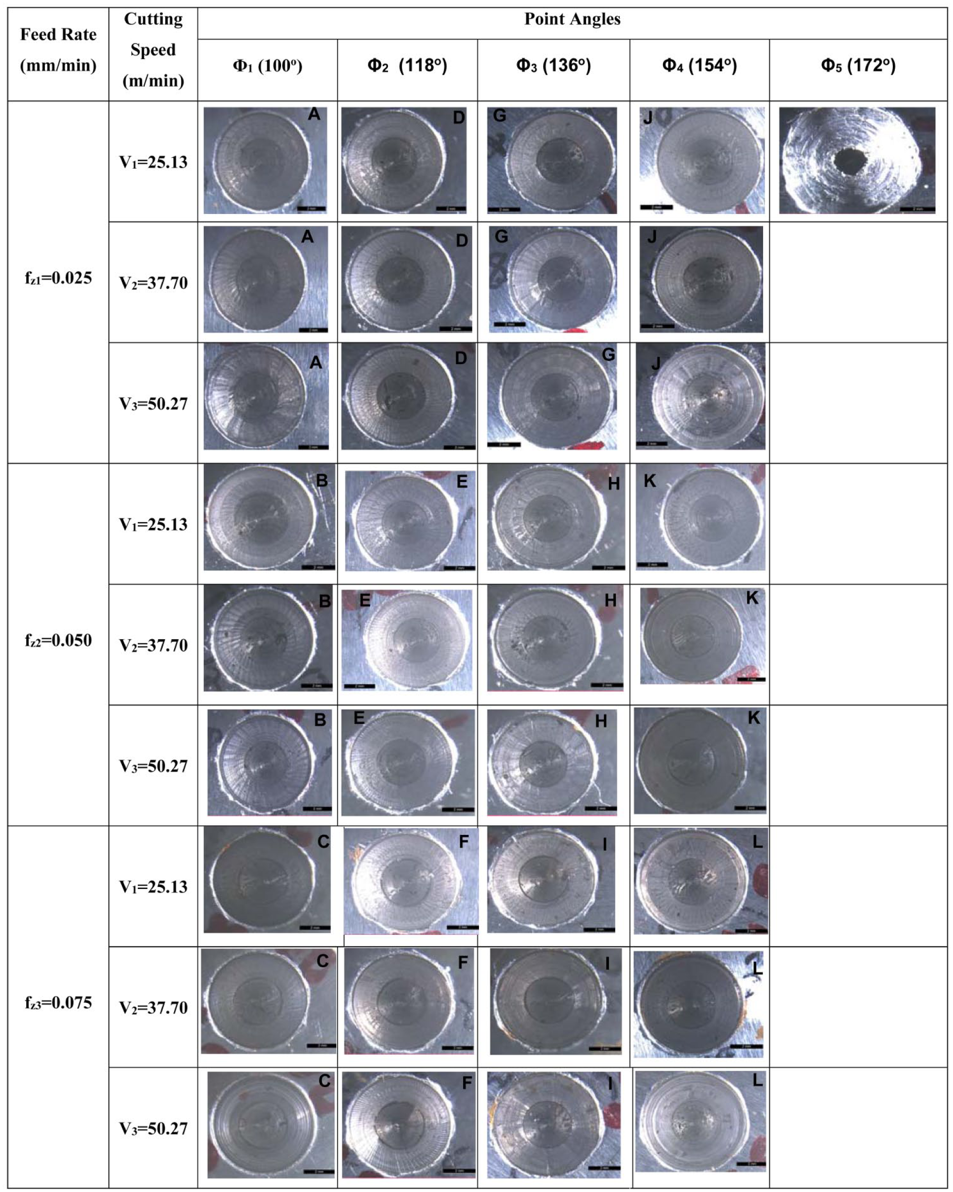
The pictures and chipping at the entry of the holes.
Surface roughness in drilling operations
The main effects of the drilling parameters on surface roughness are shown in Figure 9. As shown in Figure 9(a), the average recorded roughness values of the holes decreased with changing feed rate, spindle speed, and point angle from the minimum to the maximum selected values, regularly. However, the effect of the spindle speed on the surface roughness values was less than the feed rate and the point angle.
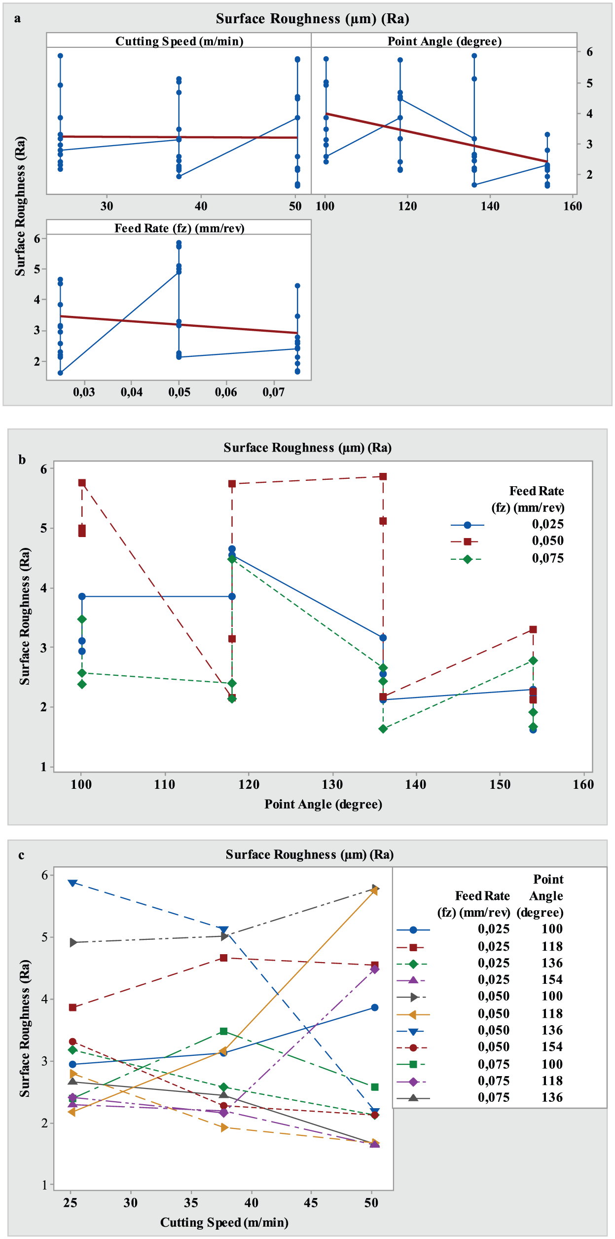
The variation in surface roughness in pre-drilled drilling of AISI 1050. The effect of a) all selected parameters, b) the point angle in details, c) the cutting speed in details, on the alterations of the surface roughness in drilling.
As shown in Figure 9(b), it is concluded that the surface roughness values demonstrate discrepancy depending on the feed rate, spindle speed, and point angle. When the point angle is selected between 100°–136°, the maximum surface roughness values were recorded at 0.050 mm/rev feed rate, but the lowest values were gained at 0.075 mm/rev feed rate, for all of the selected point angles. According to the Figure 9(c), the surface roughness increased at lower point angles, at all feed rates, and with increasing the spindle speed. However, at higher drill point angles, the surface roughness values decreased with uprising the spindle speed. In conclusion, the maximum roughness values were gained only at 0.050 mm/rev feed rate, at lower point angles, and at higher spindle speeds. In other words, the higher parameters were not appropriate, at selected higher point angles, according to the surface quality criterion. The maximum surface roughness values at 0.050 mm/rev feed rate, 50.27 m/min cutting speed, 100° and 118° point angles were recorded as 5.716 and 5.746 µm, respectively. Moreover, at the same feed rate, 136° point angle, 25.13, and 37.70 m/min cutting speeds surface roughness values were recorded as 5.887 and 5.127 µm, respectively. The minimum surface roughness, which are desirable results in metal cutting manufacturing, at 0.075 mm/rev feed rate, 50.27 m/min cutting speed, 136° and 154° point angles, were recorded as 1.644 and 1.672 µm, respectively. Besides, at 0.025 mm/rev feed rate, 154° point angle and 50.27 m/min cutting speed, the recorded surface roughness was 1.629 µm. In these premises, according to this study, higher point angles and cutting speeds but lower feed rates were optimum to gain desirable surface roughness values in pre-drilled drilling operations.
Conclusion
In machining operations, recorded results, such as cutting forces, tool wear, surface roughness, process temperature, and having determinant effects on machinability, depend on selected parameters by the operator. They are feed rate, the undeformed chip thickness, and width, describing undeformed chip area. Increases in the undeformed chip thickness and width, namely undeformed chip area, affect the machinability. The undeformed chip thickness and the undeformed chip area decreased with increasing point angle, thereby decreases occured in thrust force as well.
At high point angles, the surface quality improved, also there was a reduction in both thrust force and quantity of tool wear. The thrust force was influenced substantially by the feed rate, the cutting speed, and the point angle. In this case, at lower feed rates and higher point angles, the lowest thrust force values were gained. Also, higher point angles and cutting speeds cause providing better surface quality, as well. Even at lower cutting speed and feed rate, 172° point angle was not suitable for dry drilling operations, which were carried out at selected parameters, because of high elevation in thrust force and insufficient in projection cutting edge on the Z-axis, where the drill tool proceeding into the workpiece.
However, further studies can be made by selecting high point angles (154°–180°) and at lower feed rates, aiming to gain better surface quality, recorded less both thrust force and tool cutting-edge wear, in the drilling processes. Moreover, the performance of 172° point angle can be carried out at lower feed rates than 0.025 mm/rev and at different cutting speeds. A study can be practicable at higher drill point angles in an attempt to investigate the effect of pre-drilling diameters on the performance of the drilling.
Footnotes
Acknowledgements
The authors would like to thank the Dicle, Firat and Sabanci Universities in Turkey for contributing to the experimental study.
Declaration of conflicting interests
The author(s) declared no potential conflicts of interest with respect to the research, authorship, and/or publication of this article.
Funding
The author(s) received no financial support for the research, authorship, and/or publication of this article.