
Abstract
Background
Force offset is an important movement and control parameter in rocket motor development process, and its accurate measurement is a vital guarantee of rocket motor reliable operation, so there is an essential significance to achieve accurate force offset calibration.
Methods
A novel force offset nonlinear calibration method is proposed based on deep belief network. Experimental platform is established and force offset calibration test is completed. Because the Levenberg -Marquardt process has the advantage of both Newton method and gradient descent method, test data are trained with Levenberg -Marquardt, decreasing nonlinear mapping convergence errors and realizing nonlinear calibration of force offset.
Results and Conclusions
Training results show that the mean deviation rate of force offset after nonlinear calibration is less than 2.7%, better than the back-propagation neural network and least squares method, verifying the reasonableness and practicality of nonlinear compensation calibration method and effectively improving force offset calibration accuracy.
Introduction
With an increasing development in space technology, facing more and more accurate control requirement of orbital motion for spacecraft, accuracy adjusting to attitude and correcting track become crucial for rocket motor. Thrust is an important performance index of rocket motor, directly influencing motor performance and movement accuracy. 1 When rocket motor is jetting, due to some factors of propellant uneven combustion and nozzle axis offset, rocket thrust deviates its axis, resulting in force offset. Therefore, it is an important guarantee to accurately obtain force offset and other critical parameters for improving the movement of rocket motor.
As of thrust measurement, there is a great difference between range of force in main direction and that in lateral direction, which belongs to a problem of large range rate in main and lateral directions. Small lateral force is easy to be submerged under large main force, which can induce lateral nonlinear error and increase the difficulty in force testing. In addition, assembly error of device and manufacture error can also decrease the force testing accuracy.
Calibration is a technique of obtaining relationship between inputs and outputs in experiments. According to force measurements, calibration can obtain core parameters such as sensitivities, which are used in online test. Thus, calibration is a key technique for precise force measurement, and it is essential to conduct force offset calibration similarly.
Calibration compensation technique is utilized for measurement. At present, a large number of papers, mainly concentrating on hardware compensation method, calculation algorithm and other methods, have researched calibration compensation methods. Li et al. 2 have studied hardware calibration technology of force sensors based on signal processing, computer intelligence and intelligent processing. Gao and Sun 3 and Xing et al. 4 have, respectively, applied the least squares method to achieve static calibration and dynamic calibration of force for the piezoelectric system. Fan and Liu 5 have studied calibration algorithm of pressure sensors based on output static characteristic. However, due to the interference in manufacturing and assembly and environmental factors, input–output characteristic of sensors still exists as a nonlinear error, so there is a need to improve testing accuracy to decrease and correct interference. Therefore, to achieve nonlinear calibration, corresponding theories and experimental methods are needed to compensate and correct nonlinear error.
The development of computer technology has made sensors intelligent and integrated, and applying intelligent methods to sensors is a hot focus in recent years. Neural network, as a large-scale nonlinear dynamic system, has been widely applied to pattern recognition, intelligent control and other fields due to parallel processing and fault-tolerant, self-adapted and self-studying abilities. However, neural network has some drawbacks such as slow speed, easy to fall into local minimum point and non-convergence in multi-layer networks, so it has been replaced by deep learning. Hinton 6 started the tide of deep learning in academic circles and industrial circles. Deep learning can achieve complex function approximation by learning a deep nonlinear network structure, which unfolds powerful learning ability from few training samples. In fact, deep learning can learn more useful characteristics by constructing a machine learning model with multi-hidden-layer and massive training data, improving the accuracy classification and prediction. At present, deep learning includes DBN 7 (deep belief networks), CNN 8 (convolutional neural networks), SAE 9 (stacked auto-encoders) and other methods. As an important deep-learning algorithm, 10 DBN is mainly applied to visual recognition,11,12 speech recognition 13 and error compensation, but the application of DBN to sensors is very few. Wang et al. 14 applied DBN to implement fault diagnosis. Lu et al. 15 put forward a method based on DBN to solve the difficult problem of flexible sensors’ manufacture parameter. At present, papers on sensors based on DBN are mainly about characteristic recognition and fault diagnosis, and there are few research works on sensor calibration.
Therefore, in this paper, a nonlinear compensation model between output voltage and calibration force is established on the force calibration platform, and nonlinear mapping for representing high dimensional data is established based on the Levenberg–Marquardt method. The problem with higher convergence error based on gradient descent algorithm DBN is solved to achieve nonlinear correction of force offset. Compared with back-propagation neural network (BPNN) and linear least squares method for calibration, reasonableness of DBN compensation method and input–output structure are verified.
Force calibration system of force offset
Setup of the calibration platform
According to the requirement of test, taking piezoelectric dynamometer as a core force-sensitive component, force calibration system of force offset is designed. As shown in Figure 1, the total system consists of hydraulic loading device (Shaanxi Creat Wit Technology CW8610T), calibration platform, charge amplifier (Sinocera Piezotronics LN5861), data acquisition (Data Translation DT9804), computer and software. According to the experimental conditions for actual engine emission, loading force can be accomplished by the hydraulic loading device. Based on the piezoelectric effect, sensor’s induced charges are formed by force acting on the calibration platform, and output voltage of force can be obtained by data processing of charge amplifier and data acquisition.
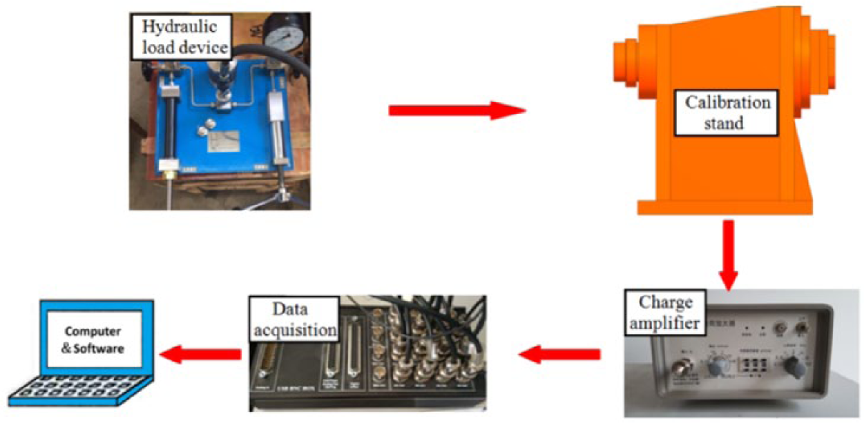
The diagram of calibration system.
The core of the calibration system is force calibration platform of force offset, as shown in Figure 2. Force in the main direction is generated by hydraulic loading device in the force source generator, and through standard sensor, loading rod, self-centering device and piezoelectric dynamometer, eventually the output of force can be obtained. The standard sensor located between the piezoelectric dynamometer and the loading rod can accurately measure the value of resultant force to calibrate Fx, Fy and Fz.
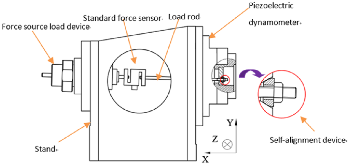
The structural diagram of force calibration platform.
The position of force can be adjusted by the force source generator and self-centering device to achieve the accurate calibration of force offset parameters—α, δy, δz. Different misalignment angles α are calibrated by changing the angle between load rod’s axis and horizontal direction in the force source generator. δy and δz denote the offset loading position in the Y and Z axes. δy and δz in multi-workstation loading of the different offset are accomplished by rotating the self-centering device.
Introduction of the experimental principle
Piezoelectric dynamometer consisting of multi-sensors can be adopted in order to calibrate force offset and obtain function mapping between force and force offset. The accuracy and difficulty of test in solving force offset are influenced by space arrangement of multi-sensors. 16 In order to reduce crosstalk and simplify calculation, the force platform consisting of four sensors with square layout is adopted, as shown in Figure 3(a) and (b). Fxi, Fyi and Fzi (i = 1–4) of X, Y and Z axes are, respectively, measured by four three-dimensional sensors.
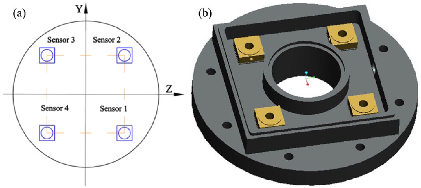
The dynamometer consisting of four sensors with square layout (a) Diagram of layout of sensors and (b) picture of layout sensors.
The mathematical model of the calibration platform is as follows, as shown in Figure 4. The theoretical axis of rocket engine is X axis, the point O is the theoretical geometric center of force in rocket engine, Y′O′Z is the loading plane of force in rocket engine and YOZ is the contact plane of four sensors, forming the Cartesian coordinate system X-YOZ and X-Y′O′Z, where Fxi, Fyi and Fzi are the value of each sensor in direction X, Y and Z.
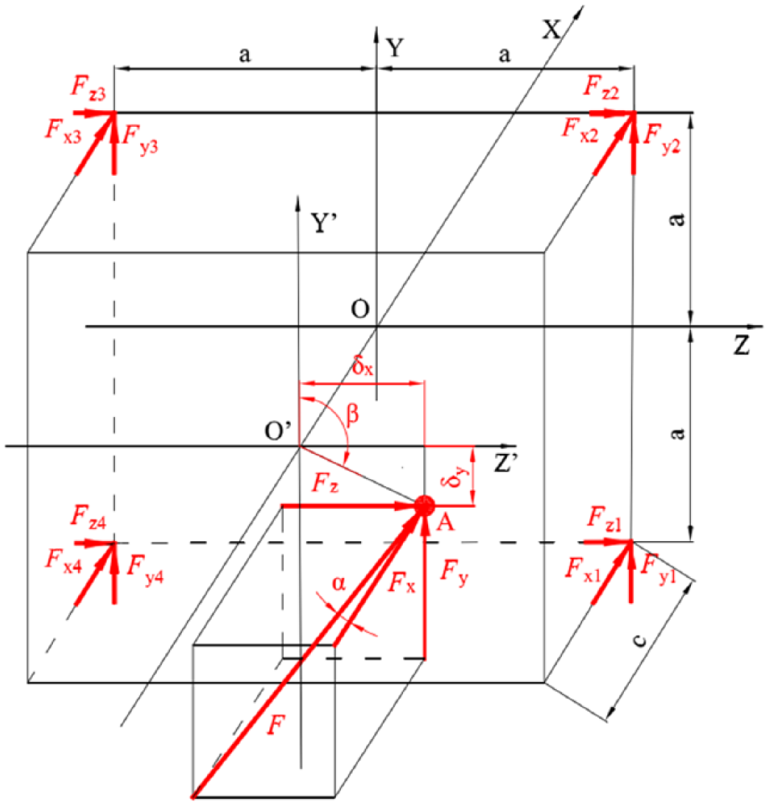
The model of calibration platform.
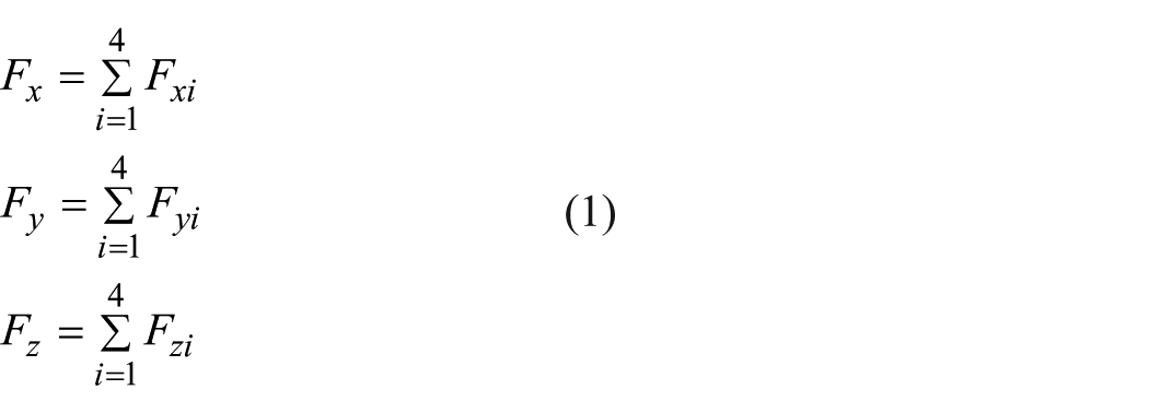
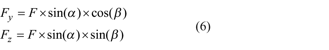
Based on the principle of theoretical mechanics, forces in three directions Fx, Fy and Fz are as follows
Force offset parameters, including main misalignment angle α, offset δy in the Y direction and offset
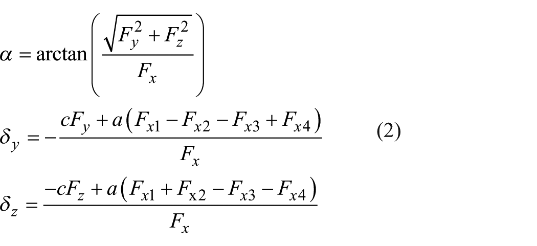
According to equation (2), if the values of Fx1, Fx2, Fx3, Fx4,
DBN calibration compensation mapping
Introduction of DBN
As an unsupervised depth learning structure, DBN can extract the essential characteristics of the model and improve the processing accuracy of the network. 18 DBN includes a series of layers of restricted Boltzmann machine (RBM). In order to obtain more effective learning weights, RBM as the core of DBN, pre-training network is achieved by an unsupervised greedy layer. In the training process, first, the visual input units are mapped into the hidden layer, and input units are reconstructed from the hidden layer through RBM; these new visual units are mapped to the hidden unit again to obtain a new hidden layer unit, as shown in Figure 5.
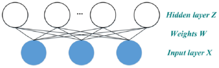
The diagram of RBM structure.
Provided that the amount of input layer and hidden layer units are m and n,
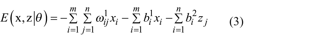
where
New weights and threshold are constantly updated using the Markov chain Monte Carlo characteristic of making input layer and hidden layer mutual conditions, in order to make them tend to be steady.
19
Based on the probability gradient
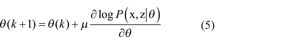
where μ is the learning rate. To achieve convergence error as small as possible, global energy is minimized after several corrections.
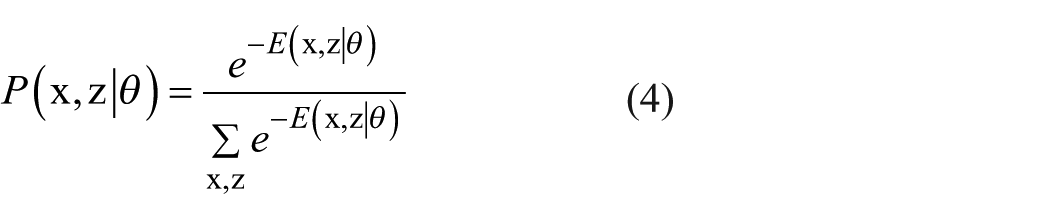
According to the above-mentioned equations, nonlinear mapping between voltage and force is constructed with DBN in practical calibration to improve calibration accuracy. DBN is a nonlinear mapping method with multiple layers built by experimental data in order to improve calculation accuracy. The RBM optimization method is applied to build error relation of nonlinear mapping, which can reduce to minimum. In order to make the error minimum, RBM corrects coefficients (namely, weights and thresholds in paper) by multiple trainings and can make optimization function (namely, joint probability in paper) minimum. Energy function of each layer can be used to express joint probability. Equation (3) denotes the energy function of each layer and equation (4) denotes the joint probability of each layer, and then joint probability can be reduced by correcting weights and thresholds of equation (5).
Network structure of DBN
It is essential to determine the network structure of DBN, namely, to determine input and output layers of parameters (voltages, forces and force offsets). For a multiple input–output layer network, determining the parameter of input layer and output layer is the primary assignment. Before accurately calculating force offset parameters
Choosing output layer parameter is not only mainly determined by target parameter but also related to experimental condition and other factors. Based on force calibration platform, two types of input layer structures of DBN are designed.
Output layer with α, δx and δy structure
As shown in Figure 6, output layer is the structure of α, δx and δy. Building a double-level output model with six-dimensional input and three-dimensional output can directly express force offset parameter, and the structure is simple. Apart from the way of DBN, compensation of force offset parameter is achieved without other calculations, which is an ideal nonlinearity compensation model.
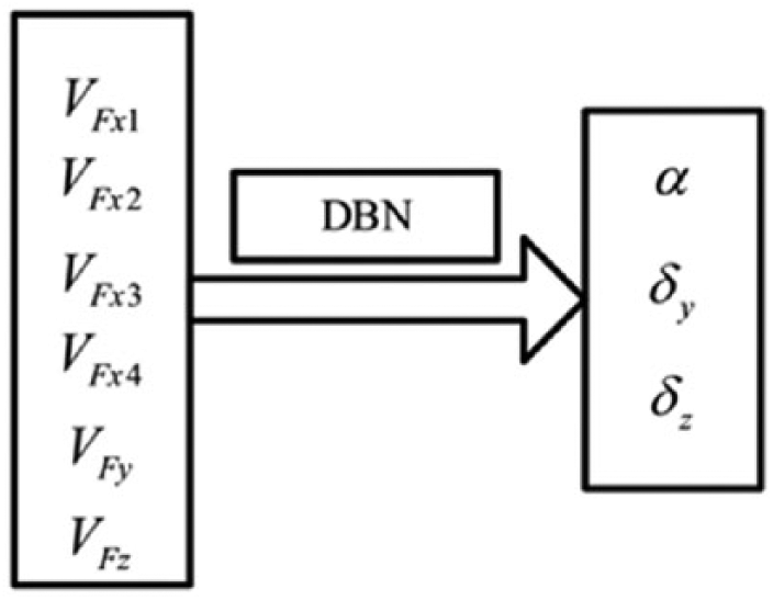
The input and output structure of A scheme.
Output layer with Fx1, Fx2, Fx3, Fx4, Fy and Fz structure
As shown in Figure 7, output layer is the structure of Fx1, Fx2, Fx3, Fx4, Fy and Fz. Force offset compensation values (
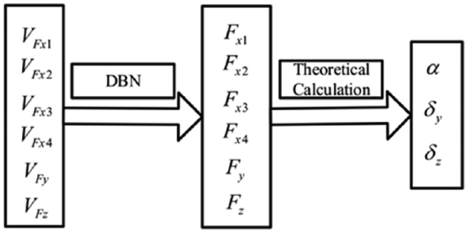
The input and output structure of B scheme.
Compared with schemes A and B, the force offsets must be adjusted by changing the misalignment angle and loading positions of force source generator. The structures with different misalignment angles and loading positions must be, respectively, manufactured in the experiments, which increases cost and generates extra manufacturing nonlinear error, which is different from measurement condition, so compensation structure B should be chosen.
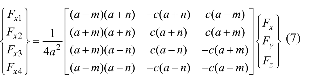
Thus, the main thought of nonlinear method is that the mapping between input voltages parameters (
According to the literature, 20 the calculated equation of value Fx1, Fx2, Fx3 and Fx4 is as follows.
DBN structure based on the Levenberg–Marquardt algorithm
BP is the last layer of DBN processing, whose generalization precision is related to the correction algorithm of weights and thresholds. BP of DBN generally adopts the gradient descent method, which has a good effect on non-supervised learning for visual recognition, but in labeled nonlinear calculation, it can process a large convergence error. Levenberg–Marquardt 21 is an improved algorithm for Gauss-Newton’s method, not only having the characteristic that can search directions in partial optimization but also having the characteristic of gradient method in overall situation, whose convergence speed is further faster than the gradient descent method. 22
As shown in Figure 8, the DBN structure based on the Levenberg–Marquardt algorithm is presented. The total structure consists of normalization process, several layers of RBM and a BP with one layer based on the Levenberg–Marquardt algorithm. Force acting on calibration platform and output voltages are corrected by RBM after normalization process and are trained with weights and thresholds by BP based on the Levenberg–Marquardt algorithm, until achieving training times or normalization error being less than target error, to achieve nonlinearity compensation network of DBN. After output value is compensated by DBN and inverse-normalized,
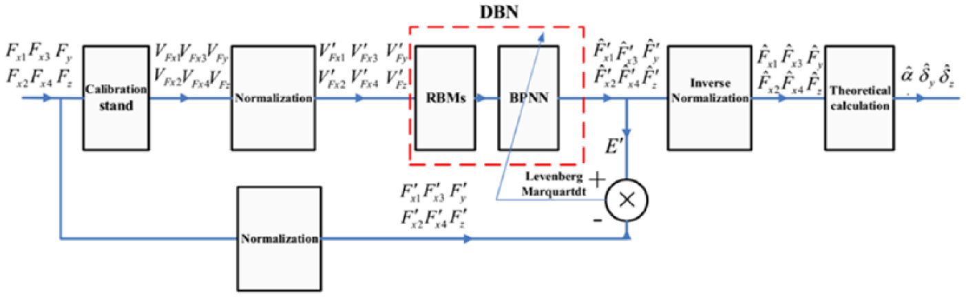
The structure of DBN.
Simulation
Experimental data are nonlinear compensated based on DBN, using calibration platform to achieve calibration experiment. In order to express the accuracy of nonlinearity compensation method, multi-workstation experimental data are evaluated in terms of error, which verifies the abilities of generalization and nonlinearity compensation.
Test
The experimental picture of the calibration device is shown in Figure 9. Based on the calibration experimental platform, in order to consider the misalignment generated by manufacture error in different directions, the plane of force loading device is divided into eight parts in average, that is, eight workstations. The experimental data of eight-direction loading are obtained by rotating the force source loading device and changing the force loading position to calibrate eight force offset δy, δz. Eight directions are designed to eight workstations, which are shown in Figure 10(a) and (b). Total forces F of 500, 1000, 1500, 2000, 2500, and 3000 N are loaded, respectively, in every workstation. In order to obtain stability and repeatability of data, each loading is carried out five times, and the amount of experimental data adds up to 240 groups and 1440 force values.
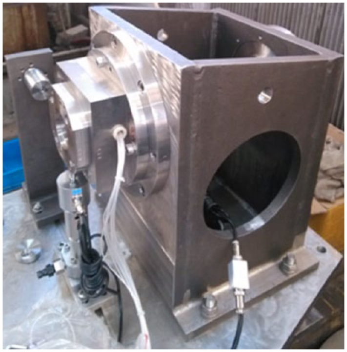
The experimental body of force calibration device.
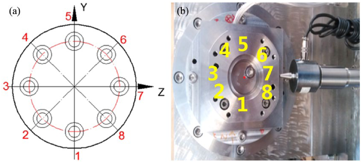
Eight workstations of force platform (a) Diagram of eight-workstation direction and (b) picture of eight-workstation direction.
DBN training compensation and analysis
DBN contrast tests based on the Levenberg–Marquardt method and gradient descent method are achieved, and then nonlinearity compensation of sensor’s main force offset parameter is achieved using force calibration platform based on DBN of the Levenberg–Marquardt method.
Based on experimental data, the first four experiments of each force with eight workstations are regarded as training samples with a total of 192 groups and 1152 forces; in addition, the last experiment is regarded as verified sample with 48 groups and 288 force values. In order to obtain nonlinear mapping of higher generalization accuracy, the DBN structure of hidden layer and evaluation index are expressed respectively.
Convergence speed and calculation accuracy are influenced by the amount of DBN hidden layer. Compared with shallow learning methods such as BP (Back Propagation), DBN can build several layers of hidden networks and learn more useful characteristics to improve the generalization accuracy of network. 23 Therefore, hidden layer with double 100 units based on RBM is built to achieve the network of several hidden layers.
What’s more, ensuring evaluation index is a necessary process of measuring the accuracy of fitting method. Integrating analysis of large number of data, the applied evaluation index includes RMSE (Root Mean Standard Error), MDR (Mean Deviation root) and relevance index R2. 24
RMSE is an index measuring the value of average deviation for overall data, MDR is an index measuring the average deviation ratio of data and R2 is an index measuring the relevance degree of multiple variables.
In order to verify the reasonableness of DBN based on the Levenberg–Marquardt method, DBN based on the gradient descent method is utilized to compare with it. SSE of BP with 100 iterations is analyzed based on 192 groups, adopting 6-100-100-6 input and output structure, where the generalization range is [0, 1], the learning ratio of RBM is 0.95 and the number of iterations of RBM is 5. Normalized SSE of two methods is as shown in Figure 11.
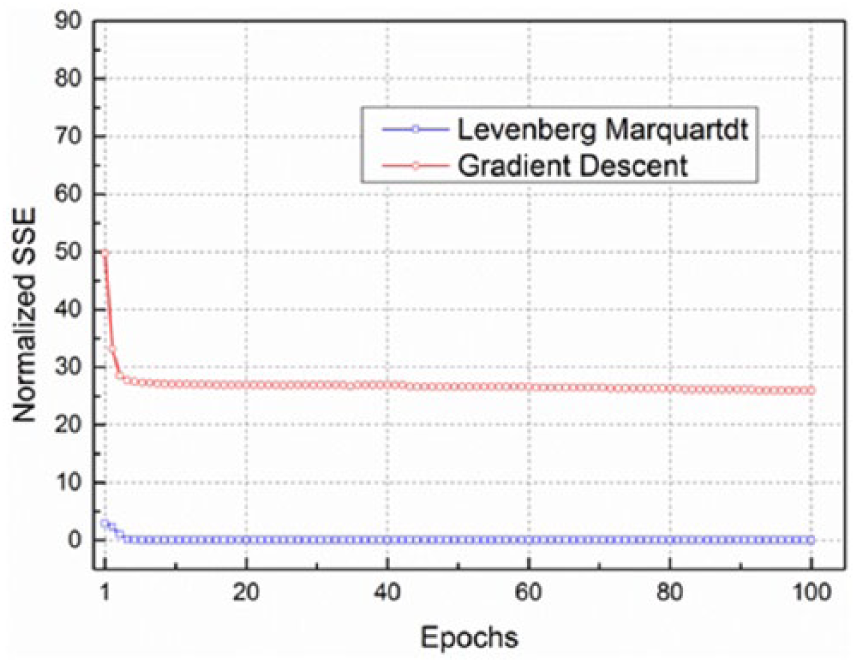
Normalized SSE based on DBN of the Levenberg–Marquardt method and gradient descent method.
From Figure 11, we can see that DBN based on the gradient descent method has been partial minimum in the 100 epochs, whose normalized SSE is obviously larger than DBN based on the Levenberg–Marquardt algorithm, which shows the method based on Levenberg–Marquardt is effective, so DBN based on the Levenberg–Marquardt algorithm is chosen. In addition, due to the curve converging based on Levenberg–Marquardt rapidly when training epoch is about 10, training epoch of 30 is chosen in order to balance the relationship between convergence accuracy and training times.
Based on the above contrast, nonlinearity compensation model based on the Levenberg–Marquardt algorithm is designed. The parameters are similar to above contrast test, and the maximum training epoch is 30. Based on 192 groups of samples, δy, δz of eight workstations before and after training are shown in Figure 12, where five-point star denotes the desired value of eight workstations. In order to express the relationship between δy, δz and desired value, partial data of seven workstations are magnified.
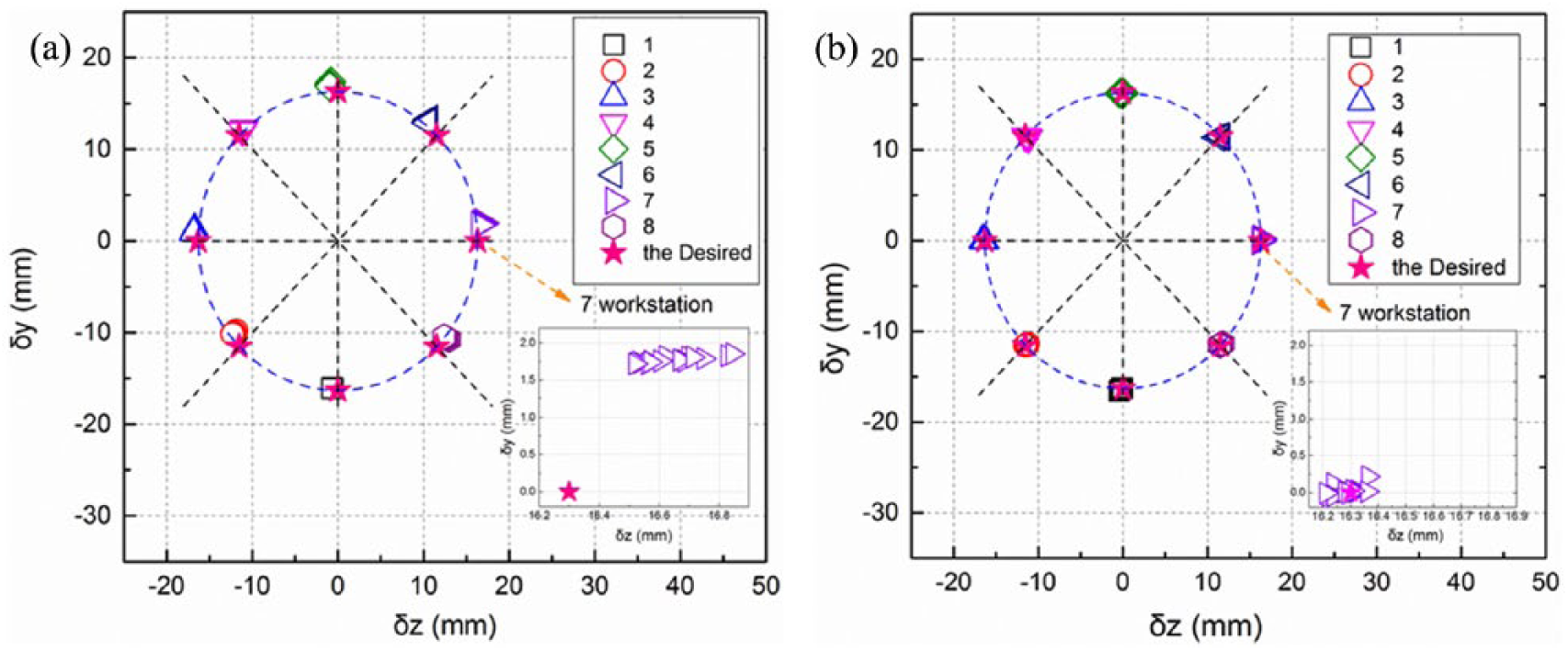
δy, δz of DBN training (a) before and (b) after eight workstations.
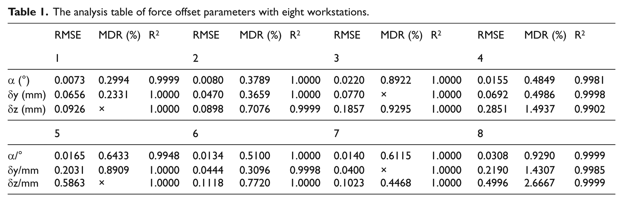
Fifty-six training data are compensated based on nonlinearity compensation mapping after training, and force offset parameters α, δy, δz are analyzed. The table between force offset parameters
The analysis table of force offset parameters with eight workstations.
In order to verify DBN compensation ability, force offset parameters of 56 groups of verified data are fitted with BPNN and least squares method compared with DBN method, and the contrast table is shown in Table 2.
The contrast of force offset parameters among DBN, BPNN and least squares method.

From the correction of force offset, RMSEs of α, δy, δz based on DBN are, respectively, 0.0175°, 0.1173 mm and 0.3059 mm, which are obviously less than the value of BPNN (0.0873°, 0.7583 mm and 0.6433 mm) and least squares method (0.2056°, 0.8403 mm and 0.804 mm). MDR of
In order to analyze the compensation ability of different methods with eight workstations, RMSEs after DBN, BPNN and least squares method of force misalignment parameter compensation and partial workstation MDR are shown in Figure 13. RMSE, MDR and DBN of each workstation are less than BPNN and least squares method. The curve of RMSE and MDR with least squares method fluctuates seriously; BPNN is better than the least squares method in general. Because errors of the force offset parameter compensation method exhibit randomness, the tendency of evaluation index of each workstation is also random. In general, the BPNN and least squares method have higher randomness, and fitting accuracy and reliability of above methods are lower than DBN compensation.
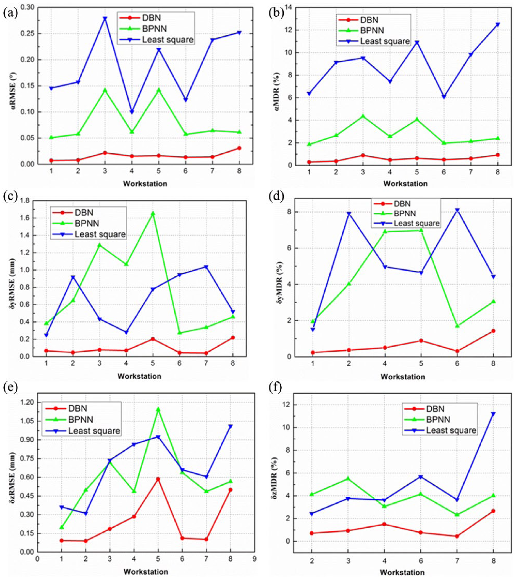
The contrast of RMSE and MDR after force offset parameters with DBN, BPNN and least squares method in eight workstations (a) RMSE of a (b) MDR of a (c) RMSE of dy (d) MDR of dy (e) RMSE of dz (f) MDR of dz.
Discussion
Sample quality and network structure
The compensation accuracy of DBN is influenced by sample quality. High-quality sample can provide total training sample information, 25 namely, having to comprehensively respond to input–output reflection total tendency and distribution, including pole and other critical mapping points. Massive sample number can not only increase algorithm difficulty and epoch but can also lead to overfitting phenomenon.
Enough samples cannot be obtained due to experimental condition restriction and mapping with higher nonlinear and complex structures. The lack of samples for mapping can lead to errors of partial deviation and leakage solution. In this paper, a network structure, including DBN nonlinear mapping and theoretical calculation, is put forward to solve this problem. Due to nonlinear mapping without complexity in the process, few samples can also obtain higher generalization accuracy and calculation efficiency.
Weight and threshold correction algorithm
Both convergence rate and accuracy are influenced by weight and threshold correction algorithm of BP in the last layer of DBN. Generally, although the convergence rate of the last layer based on gradient descent algorithm DBN is higher, error is still large when epochs are large enough. So gradient descent algorithm cannot deal with data in labeling supervised learning. In this paper, the problem with larger convergence error is solved based on the Levenberg–Marquardt DBN method, which achieves higher accuracy nonlinear compensation.
Conclusion
Establishing the DBN model based on force calibration platform is the basic for achieving force offset nonlinear compensation. In order to improve the measurement accuracy of rocket force, force calibration platform and nonlinear calibration model between sensors’ outputs and force expectation values are, respectively, established. Main conclusions are as follows. Compared with DBN based on gradient descent algorithm, DBN based on the Levenberg–Marquardt algorithm has many benefits that convergence error is obviously lower and training epochs are less. DBN algorithm based on the Levenberg–Marquardt algorithm achieves nonlinear compensation of sensor force offset parameter with force calibration platform. MDR of force offset parameters after nonlinear compensation is less than 2.7%, which is better than the traditional BP algorithm and least squares method, and its nonlinear errors decrease effectively, showing higher fitting and generalization abilities. There is a better prospect for neutral network nonlinear compensation in rocket force testing field.
Footnotes
Funding
This research is funded by National Natural Science Foundation of China (Grant No. 51475078 and Grant No. 51675084).