
Abstract
As a key part of the articulated arm coordinate measuring machine, the probe can determine the measurement accuracy. Therefore, the error source and influencing factors of the equivalent diameter of the probe are studied. First, the influence of the primary factor of the measuring force on the equivalent diameter of the probe is studied by analyzing the influence degree of its error source. Second, a mathematical model of the relationship between the equivalent diameter and the measuring force of the articulated arm coordinate measuring machine is built to compensate for the equivalent diameter error caused by the measuring force by the simulated annealing method. To illustrate the application advantage of our proposed study, a simple force-measuring device is designed based on this model. The experimental result shows that the maximum error reduction is approximately 43 µm, while the average error reduction ranges from 33 to 4.0 µm, which represents an 87.7% improvement. Overall, our proposed method can effectively compensate for the equivalent diameter error caused by the measuring force. This method can improve the accuracy of the articulated arm coordinate measuring machines on both calibration and measurement.
I. Introduction
The articulated arm coordinate measuring machine (AACMM) is a coordinate measuring system based on a rotating joint and a rotating arm, which replaces the length measurement reference with an angle measurement reference. Compared with the traditional coordinate measuring machine (CMM), the AACMM has the advantages of a simple mechanical structure, small volume, high efficiency, lightweight, large measuring range, flexibility, convenience, low cost, and field measurement capability. It is widely used in automobiles, ships, mechanical processing, and other areas. AACMM is composed of a set of rigid bodies connected by joints and realizing a kinematic chain. Each joint realizes a rotation. 1 The AACMM combines the robot arm with the CMM to have the structural characteristics of the manipulator’s flexible operation and highly accurate coordinate measurement capability, both of which are widely developed and applied characteristics. The probe system consists of a probe and a subsidiary body. The accuracy of the probe, to a large degree, determines the measurement accuracy and repeatability of the AACMM. Many studies have shown that the factors that affect the accuracy of the probe include the geometry of the probe, the direction of the probe contact, and the measuring force.2–4 Domestic and foreign scholars have performed research on the trigger probe but have primarily considered CMM. Du et al. successfully compensated for the radius of the trigger probe. The method combining dynamic calibration of probe radius and micro plane compensation was put forward to make compensation for the probe radius. 5 Zheng et al. 6 improved the measurement efficiency and accuracy of the probe using a simple cone socket component, a calibration tool, and the Levenberg–Marquardt (LM) algorithm, which was edited to solve the probe parameters. Huang et al. 7 proposed a new three-dimensional (3D) resonant trigger probe based on a quartz tuning fork to achieve true 3D nano-measurement with sub-nanometer resolution and very low touch force through a micro/nano-CMM. With a touch-trigger probe on a micro-CMM, the probe cannot enter into the cavity if the tip-ball diameter is larger than the cavity size. Zhang et al. 8 presented a vision-assisted noncontact focusing probe to deal with this problem. Xu and Chen 9 used the CMM to measure the diameter of the device under test (DUT) and described the sources of uncertainty that affect the measurement results. Küng et al. thought that the role of the probe tip was particularly crucial because it was in contact with the sample surface. Understanding how the probe tip wears off would help to narrow the measurement errors. 10 González-Madruga et al. 11 analyzed the effect of measuring the force on the diameter by installing a force sensor on the probe.
The above works examine the probe of the measuring machine, and these research insights may also improve the probing accuracy to a certain extent. However, there are certain shortcomings, including the ignorance of thermal deformation,12–15 installation eccentricity, and measuring force. The stability of AACMM, the choice of probe type, the measurement point acquisition strategy, and the probe processing level all impact the measurement accuracy during the measurement process. Even for the same object, it is impossible to achieve the same results every time. Simultaneously, the measuring force is an important factor affecting the accuracy of AACMM. Local deformation of the probe and the DUT is caused by the presence of the measuring force during the contact measurement. Here, the rod is bent and deformed, which means that the true geometry of the AACMM probe does not match its kinematic equation. We can reduce the probe error by periodically calibrating the AACMM, but the effect of the measuring force is usually overlooked during the calibration and measurement process, which does not compensate for the measuring error.
In this article, first, the composition, working principle, and kinematic equation of the AACMM were introduced. Then, the error of the equivalent diameter of the AACMM was studied by analyzing the eccentricity of the probe and the influence of the thermal deformation and the measuring force on the equivalent diameter, and the maximum influence of measuring force was obtained. Finally, by designing a simple force-measuring device, the measurement coordinates of the AACMM and the corresponding measuring force are built to build the functional relationship between the equivalent diameter and measuring force to realize the measuring force error compensation. The results show that the method is effective.
II. The Working Principle and Kinematic Equation of AACMM
A. Working principle
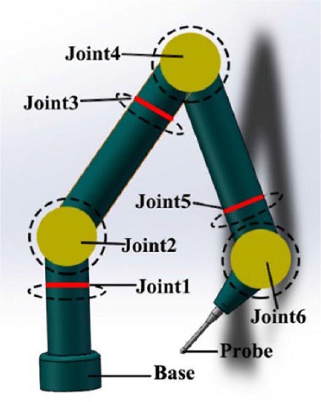
The AACMM consists of a base, two measuring arms, six angle encoders, and one probe. The utility model is formed by connecting a fixed length arm with an axis perpendicular to each other. Finally, the coordinate measurement is realized by the probe system. In the detection of a fixed point space, AACMM and CMM are completely different. When the position of the probe is determined, the positions of the X, Y and Z axis of the CMM are uniquely determined. However, the spatial positions of each measuring arm of AACMM have infinite combinations, which cannot be uniquely determined. However, the AACMM measuring the probe a fixed space point there is an infinite combination, which means that the angle and position of each arm in space is infinite, not the only. In addition, the distance of the probe from each joint is different. The influence of different levels of the angle error on the measurement results is different. The closer the cornering error of the joint at the base, the greater the influence on the measurement result. A simple AACMM structure is shown in Figure 1 . The physical map is shown in Figure 2 .
Schematic diagram of AACMM.
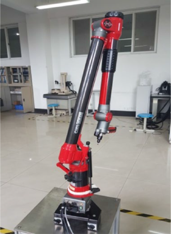
AACMM of Hexagon-Infinite 2.0.
B. Kinematic equation
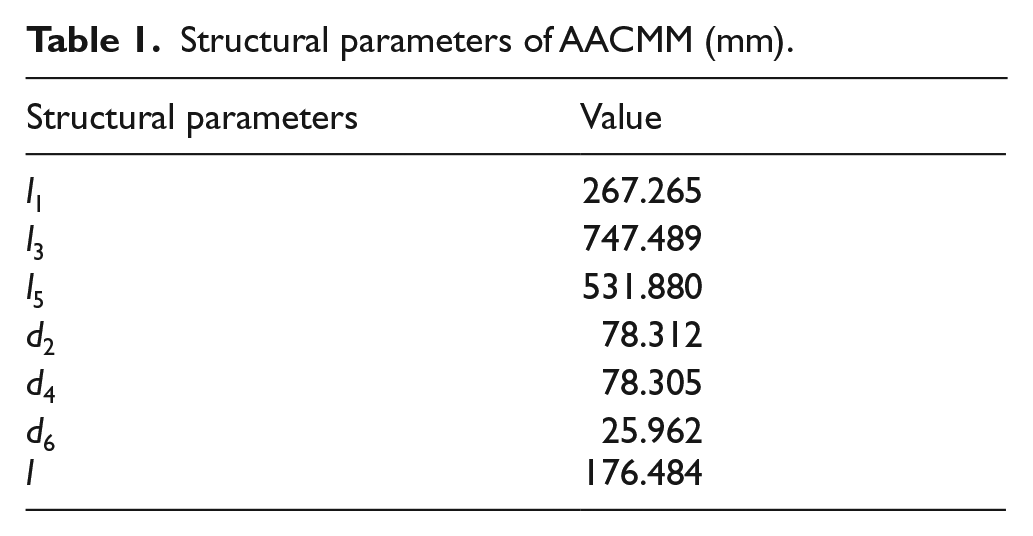
The motion equation of the AACMM is built using the mathematical model of D-H, which was proposed by Denavit and Hartenberg in 1955 to study the relative position relation of two adjacent parts. 16 The coordinates of the mathematical model of the AACMM are shown in Figure 3 . 17 The calibration value of the main structural parameters of the AACMM is shown in Table 1 .
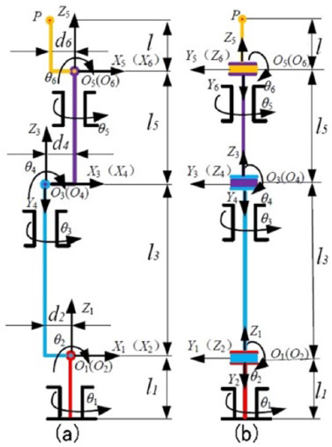
Coordinate diagram of the AACMM: (a) front view and (b) side view.
Structural parameters of AACMM (mm).
According to the D-H mathematical model, the adjacent coordinate systems
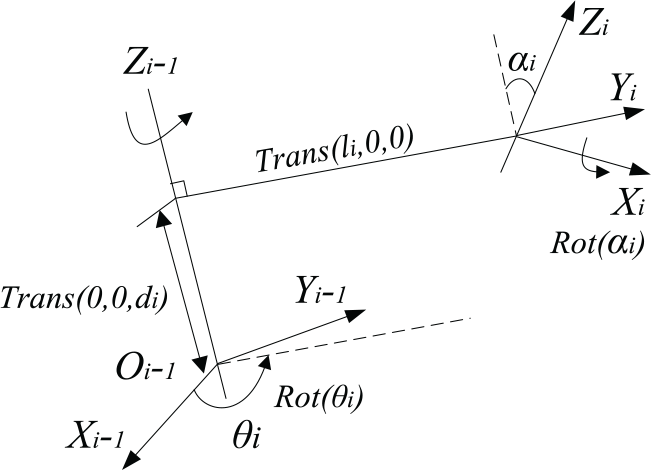
Coordinate transformation.
According to the principle of coordinate transformation, it is concluded that the conversion matrix is as follows 18
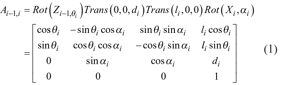
where
III. Equivalent Diameter
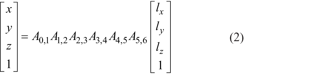
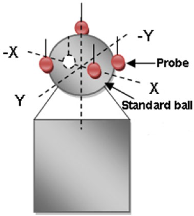
The principle of probe calibration is to measure the true diameter of the probe by measuring a standard part. The calibration of the device has a ring, ring gauge, and standard ball to achieve a full range of probe calibrations, so the standard ball is often chosen. According to the 2013 version of the “Chinese articulated arm coordinate measuring machine calibration standard,” calibrating the probe in the standard ball requires collecting at least five points, that is, one point in the ball pole and the other four on the equator, as shown in Figure 5 . The measurement software will fit a ball according to the collected spherical coordinates and can be used to calculate the diameter of the fit ball. The difference between the calculated spherical diameter and the standard ball diameter is the equivalent diameter of the calibrated probe.
Probe calibration.
A simple length measurement as an example
19
is shown in
Figure 6
. Assume that the outer dimension length and the inner one of the DUT measured by AACMM are L1 or L2, respectively. To obtain the actual length L of the DUT, it is necessary to subtract or add a probe diameter on this basis, denoted as
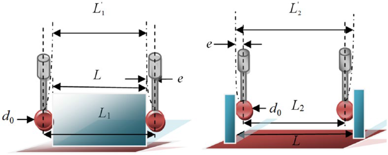
Diameter error.
IV. Error Analysis of Equivalent Diameter
When the AACMM measures the coordinates, it usually does so at the probe center. We have to get the feature points at the probe’s contact point and the DUT. The difference between these points is half of the equivalent diameter. The compensation measure is to measure the coordinates of the probe center along the measurement direction to obtain a feature point of the DUT. The probe thermal deformation, probe installation eccentricity, contact measuring force, and many physical factors can change the equivalent diameter of the probe. Figure 7 shows the primary error sources of the probe and the influence that each factor has on the probe equivalent diameter.

Influencing factors of probe equivalent diameter.
Due to experimental equipment and environmental, human, and other factors, the probe equivalent diameter is slightly smaller than the nominal diameter, which is called “equivalent diameter.” During the length measurement, the measured length is subtracted from the nominal diameter of the probe, which results in the inaccuracy of the DUT dimension. In fact, the measured length should be subtracted from the equivalent diameter. Based on the above analysis, this article focuses on the effects that the thermal deformation, eccentricity, and measuring force have the equivalent diameter of the AACMM. The most important factors influencing the equivalent diameter are analyzed theoretically.
A. Thermal deformation error
Temperature affects the performance and precision of mechanical instruments and is always a physical phenomenon. We can take steps to reduce temperature effects, but they cannot be eliminated. The AACMM and other precision instruments are also affected by temperature changes. The primary focus of the following section is to discuss the thermal deformation of the probe diameter. According to the traditional thermal deformation formula20,21

where ƞ, β, and γ are the first-order polynomial, quadratic polynomial, and cubic polynomial of the material temperature linear expansion coefficient, respectively;

Assuming that the temperature change is 1°C, the calculated thermal deformation error of the probe is approximately 0.047 µm. It is concluded that the thermal deformation has little or no effect on the accuracy of the AACMM probe when the temperature change is small. In the experiment, we ensured that the AACMM is measured at constant temperature and humidity. Thus, we could strictly control the experimental environment to reduce the thermal deformation of the AACMM accuracy, so we could ignore the temperature changes on the equivalent diameter of the probe.
B. Eccentricity error
Ideally, the AACMM measures the probe center. However, both the probe error and the installation of the measuring rod lead to a deviation of the actual location of the probe center from the ideal position. This deviation results in the eccentricity of the probe installation error, as shown in
Figure 8
. Theoretically, the ideal position of the probe should be point O, but the actual installation position is O1 due to machining or probe mounting errors, which results in an eccentricity error
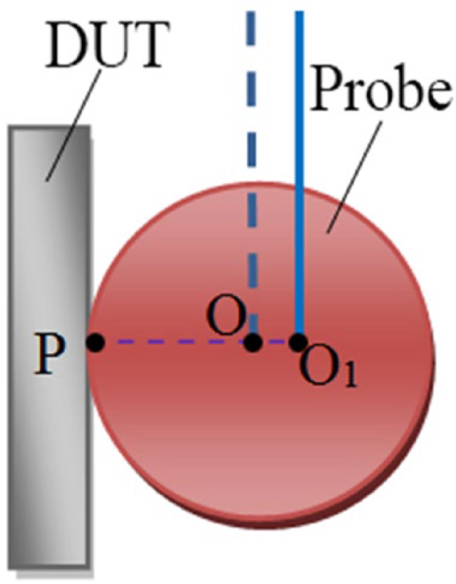
Schematic diagram of the eccentricity of the probe.
C. Measuring force
The influence of the measuring force on the equivalent diameter is primarily manifested in the deflection of the measuring rod, as shown in Figure 9 . The A state is the theoretical position of the measuring rod when the measuring force F = 0, while the B state is the operative deflect position of the rod when the measuring force F ⩾ 0. The AACMM is conducted in the B state when the coordinate is measured, and the theoretical calculation according to the D-H mathematical model is as in the A state, resulting in measurement errors. If this error is equivalent to the probe diameter, the probe diameter error is formed. According to the manufacturer’s specifications, if the other factors are not considered, the measurement force error is simply analyzed from the mechanical point of view, as shown in Figure 10 .
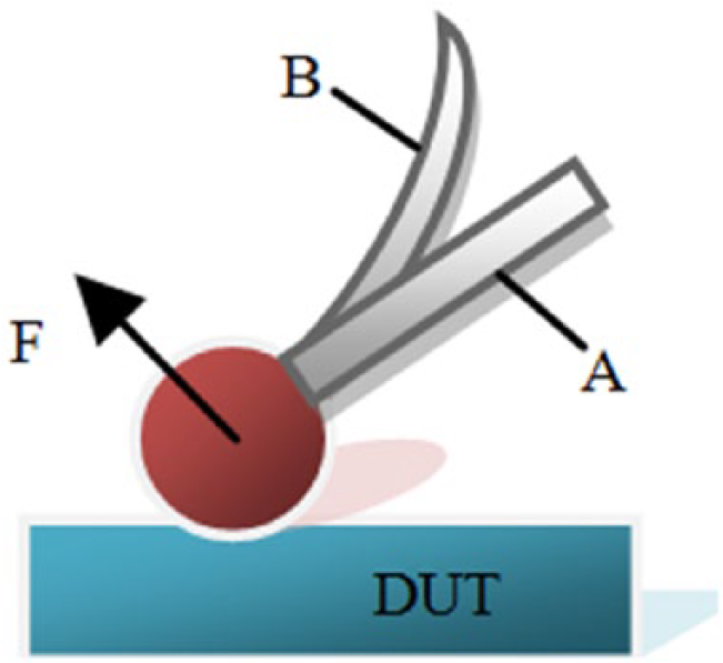
The bending deformation of the measuring rod.
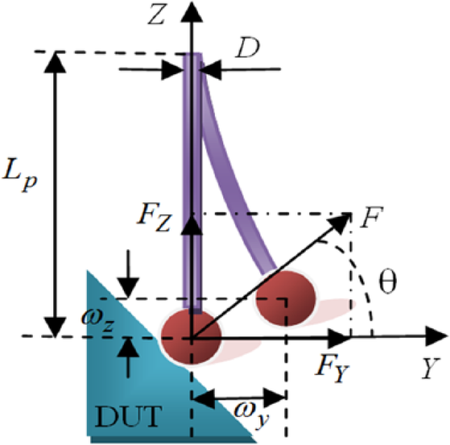
Schematic diagram of bending deformation of the rod.
In
Figure 10
, LP is the rod length; D is the rod diameter; FY and FZ are the projections of F in the XY plane and XZ plane, respectively; and q is the angle between the measuring force F and the Y-axis. Under the action of the measuring force F, the measuring rod is bent and deformed, and the transverse displacement
where E is the elastic modulus of the measuring rod and J is the inertia moment of the cross section of the rod. According to the AACMM shown in Figure 2 , the rod length of the AACMM is 15 mm, the rod diameter is 2.5 mm, and the probe diameter is 6 mm. The rod is made of stainless steel, and its elastic modulus is 190 GN/m2. Bringing together the above parameters, the 1 N transverse force to bring the lateral displacement error is approximately 3.1 µm, and the 1 N axial force to bring the axial compression displacement is approximately 0.0161 µm. In the common measurement process, assume that the measurement force applied to the probe is 5 N, resulting in a single point error of approximately 15.5 µm, and a length error of approximately 31 µm. The degree of influence of the measured force on the equivalent diameter is greatest compared with the thermal deformation error and eccentricity.
V. Equivalent Diameter Measuring Force Experiment
Through the above analysis, the measuring force has the greatest influence on the equivalent diameter of the probe. To quantitatively analyze the influence of the measuring force on the equivalent diameter, the external dimension measurement is selected as the research object. The equivalent diameter is identified by the indirect measurement method. The research method is as follows: Use the AACMM to measure the calibrator length. The measured length minus the calibrator length is the equivalent diameter of the AACMM probe, which is expressed as
A. Calibration experiment by CMM
We design a simple force-measuring device, as shown in Figure 11 . The two high-precision pressure sensors were fixed to the two ends of the metal base, and the metal base was fixed to the test bench and equipped with a display module to obtain the measuring force. The distance between two planes was measured by two sensors. The experimental data were collected on the sensor measurement plane. To avoid introducing unnecessary influence factors, we chose to measure the experimental data within the circle of a radius 3 mm from the sensor-measuring surface. With this force-measuring device, the AACMM could be achieved in the coordinate measurement while obtaining the corresponding measurement force. Then, we obtained the trend of the equivalent diameter with the measured force.
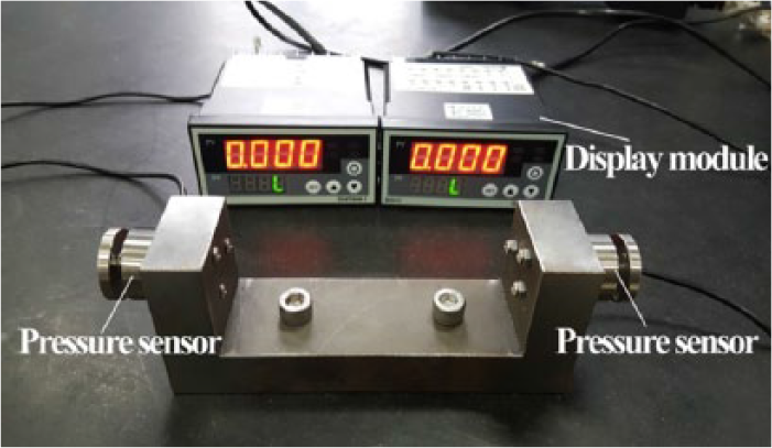
A simple force-measuring device.
Before the experiment, it was necessary to test and calibrate the force-measuring device to check whether it met the experimental requirements. Considering that the detection object is the shape and error of the two pressure sensor measurement surfaces, it primarily included the flatness of the sensor-measuring surface and the parallelism between the sensor measurement planes. When the flatness error and the parallelism error met the experimental requirements, the distance between the measurement planes could be calibrated. A more accurate CMM of the Global Class 9158 for verification and calibration is used, as shown in
Figure 12
. The steps for verification and calibration are as follows: First, 50 coordinate points on the left
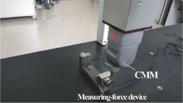
Distance calibration by CMM.
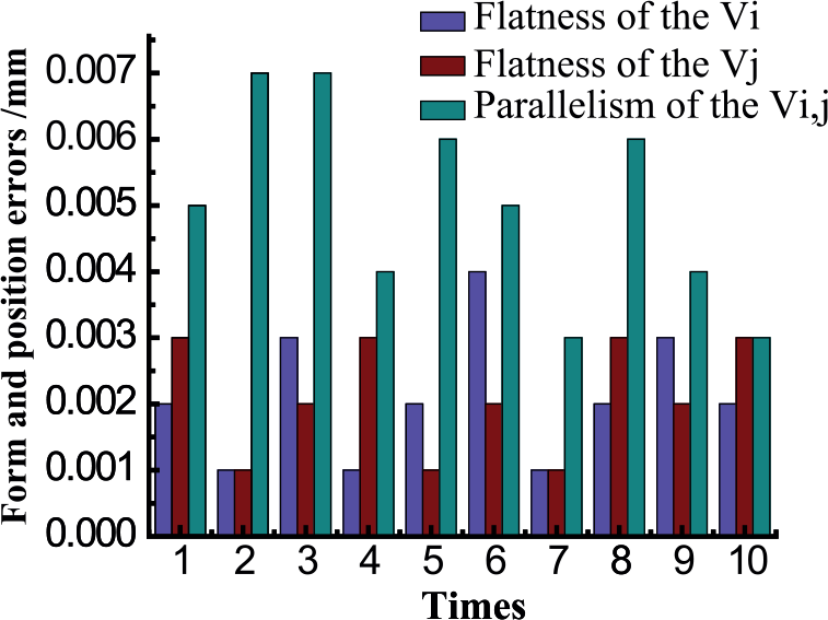
Form and position error of the two sensors.
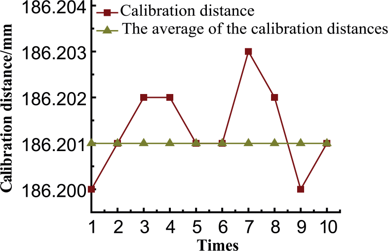
Standard distance between the two planes of the two sensors.
The test results are shown in Figure 13 , and the calibration results in Figure 14 indicate that the two measurement surfaces of the maximum flatness error of 0.004 mm have an average error of 0.0017 and 0.0021 mm, respectively. The maximum parallelism error between the measurement planes is 0.007 mm, and the average error is 0.0050 mm. The flatness error and parallelism error are relatively small, so we can ignore their impact on the experimental results. According to the experiment, the average of the 10 calibration results is considered the calibration distance between the measurement planes, denoted as L ≈ 186.201mm.
B. Effect of measuring force on equivalent diameter of AACMM
The influence of measuring the force on the equivalent diameter by the AACMM of the Hexagon-Infinite 2.0 is analyzed. The nominal diameter is 6 mm, as given by the manufacturer. The experimental scenario is shown in Figure 15 .
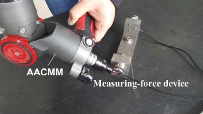
Equivalent diameter experiment by AACMM.
To analyze the effect of the measuring force on the equivalent diameter of the AACMM, the experimental method is as follows:
First,
Measuring force and the corresponding distance.
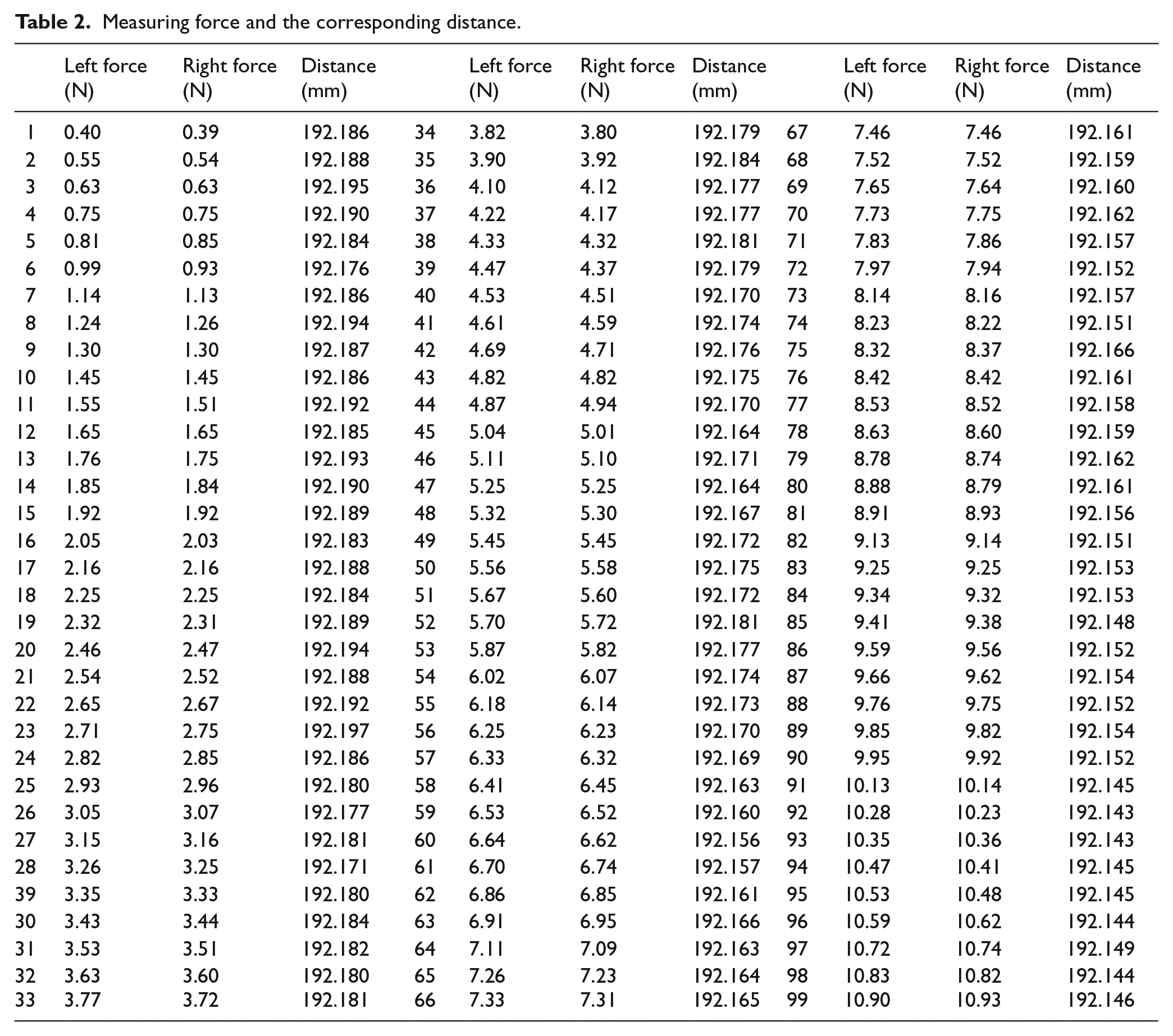
According to the data in Table 2 and the formula d = L′ − L, L = 186.201 mm, the corresponding relationship between the equivalent diameter d and the measured force F is obtained. The experimental results of the equivalent diameter and the nominal diameter are shown in Figure 16 .
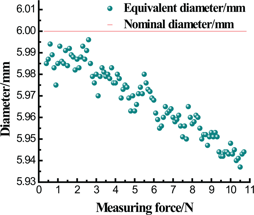
Effects of measuring force on equivalent diameter of the AACMM.
Figure 16 shows that the equivalent diameter decreases with an approximately linear trend as the measured force increases. Additionally, the test results are smaller than the nominal diameter. This discrepancy explains why the equivalent diameter of the probe is less than the nominal diameter during the calibration process. The results also show that the maximum error caused by the measuring force on the equivalent diameter of the probe is approximately 65 µm. This force has greater influence on the equivalent diameter of the probe and thus cannot be ignored.
VI. Error Compensation
To reduce the influence of the measuring force on the equivalent diameter, we must compensate for the equivalent diameter error caused by the measuring force. According to the theoretical analysis of the equivalent diameter error and the experimental results in Figure 16 , the equivalent diameter is linearly related to the measuring force. This linear relationship can be obtained by establishing the equivalent diameter and the measuring force database. The simulated annealing method is used to find the slope and intercept of the best fitting line, and the data are fitted.
The simulated annealing was first proposed by Metropolis et al. in 1953. This approach is a stochastic optimization algorithm based on the Monte-Carlo iterative solution strategy. The basic idea of simulated annealing is to find the global optimal solution of the objective function in all the solution space with the initial temperature increase and the temperature decrease or to jump out of the local optimal solution with a certain probability to achieve the global optimum.
The function

According to equation (8), the constants k and b are the parameters that determine the relationship between the equivalent diameter and the measuring force, that is, the optimized variable. Its optimization core is as follows: (1) provide the initial solution of the optimization variable; (2) iteratively optimize the variables along the appropriate optimization path, forcing the objective function to proceed in the optimal direction; and (3) when the objective function infinitely approaches zero, the optimal solution is obtained by setting the optimal termination condition. The primary flow is shown in Figure 17 .
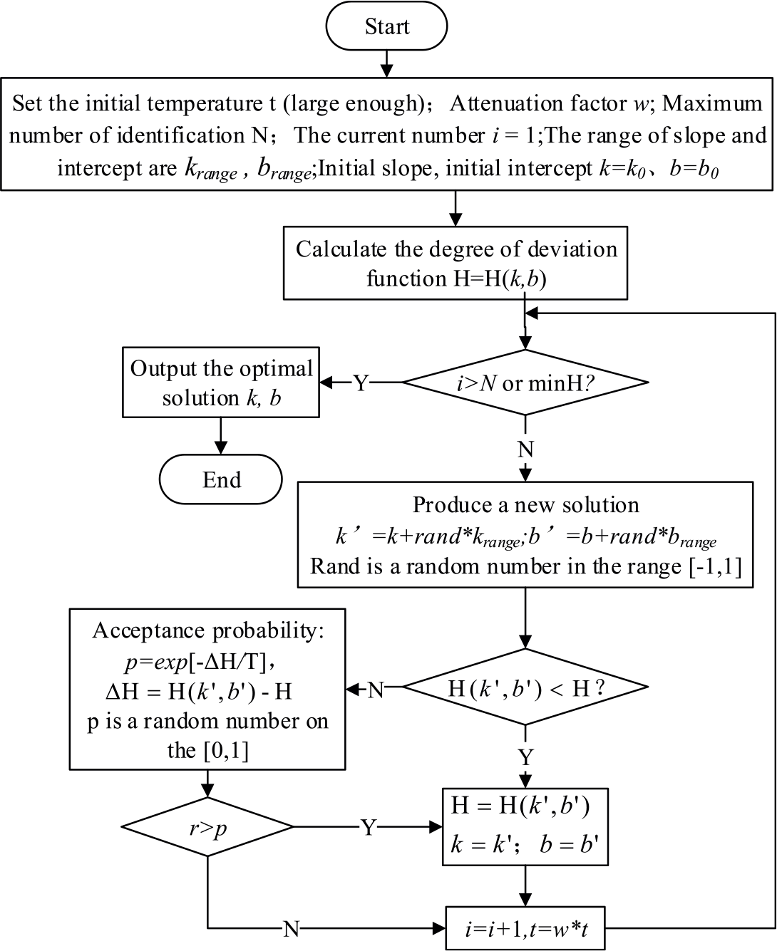
Line fitting compensation model based on simulated annealing.
According to the experimental data collected, set the initial temperature t = 900K, the attenuation factor w = 0.95, the total number of iterations N = 1000, and the initial values are

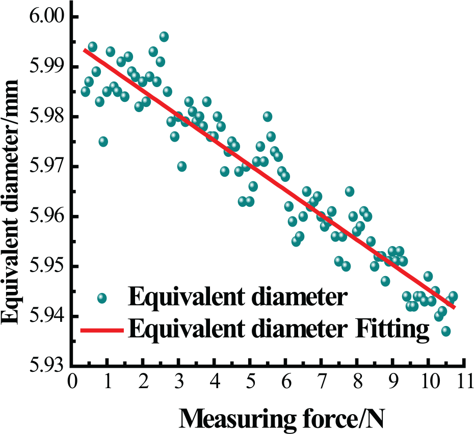
Equivalent diameter fitting.
Define the difference between the equivalent diameter and the nominal diameter of the experimental acquisition as the equivalent diameter error. Equation (9) is used as the compensation model of the equivalent diameter of the AACMM probe, which compensates for the equivalent diameter error caused by the measuring force. The error of the equivalent diameter caused by the measuring force is compensated.
Figure 19 shows that the compensation method can compensate the equivalent diameter error to a certain extent. To compare the effect of error compensation, select the compensation effect in González-Madruga et al. 11 In González-Madruga et al., 11 the authors proposed a probe deflection model based on the finite element method (FEM) in order to obtain the AACMM probe deflection caused by measuring force. From the point of view of theoretical analysis, the measurement error of probe diameter was compensated. Through his research, the precision of the AACMM is improved to a certain extent. However, this error compensation model is based on theoretical analysis, and the effect of compensation is not very satisfactory. The error compensation model in this article is based on the experimental data, the compensation model is more in line with the currently used AACMM, and the compensation effect is better. A comparative analysis of this article and González-Madruga et al., 11 the compensation effect, is shown in Table 3 .
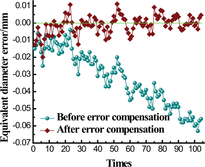
Equivalent diameter error compensation before and after.
Comparative analysis of this article and González-Madruga et al., 11 equivalent diameter error compensation before and after (mm).
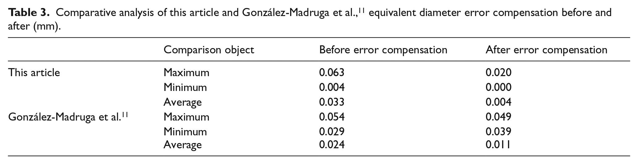
Table 3 shows that the error of the equivalent diameter is compensated such that the maximum error of the equivalent diameter is reduced by approximately 43 µm, and the average error is reduced by 29 µm. On average, the probing accuracy increased by approximately 87.7%. Comparing with the González-Madruga et al., 11 we can see that the error compensation method proposed in this article is slightly better. In terms of the average value of compensation, the average error after compensation in this article is 0.004 mm, which is better than the compensation error of 0.011 mm in González-Madruga et al. 11
VII. Conclusion and Future Work
The influencing factors of the equivalent diameter during the calibration period and measurement of the AACMM are analyzed. This analysis shows that the measuring force is the primary source of the equivalent diameter of the probe. The innovation of this study is to design a force-measuring device to realize the combination of force and coordinate measurements. The relationship between the equivalent diameter and the measuring force is defined. The equivalent diameter error caused by the measuring force is also compensated. The compensation method is verified by theoretical and experimental analyses. Our suggested method can compensate for the equivalent diameter error to a large extent and has laid a foundation for both calibration and measurement precision improvement of the AACMMs.
This research is not only for the specific AACMM but also for any AACMM when calibrating the probe. This method can be used to obtain the functional relationship between the equivalent diameter of the probe and the measuring force. For different physical materials and dimensions of the probe, the functional relationship may be different, but the method is generally applicable. At present, the research method can be realized on the basis of theory and experiment, but the actual engineering application still needs further study. In the follow-up study, we plan to apply this method to the probe calibration of the AACMM. The measuring force calibration module will be added to the probe calibration software system to further improve the calibration accuracy of the probe and through the calibration of the measuring force to improve the AACMM’s measurement accuracy.
Footnotes
Funding
This work was supported by the National Natural Science Foundation of China (project 51675499 and project 51405463) and Natural Science Foundation of Zhejiang Province (project LY15E050013).