
Abstract
This paper presents a water-level control system in a drum boiler. The system was equipped with a fault tolerant control–type diagnostic system. The paper presents the results of tests conducted on the fault tolerant control system implemented in the water-level control system in a boiler drum. The diagnostics of the measurement circuits was carried out online. To that end, the appropriate partial models were developed and tested. This allowed for the application of analytical redundancy for the measurement circuits. The paper also identifies the influence of diagnostics and fault tolerance on the values of reliability indices and operating safety of a power unit. Fault tolerant control systems increase the safety of a power unit operation, and the studies described in the paper directly contribute to them. These kinds of systems have not been used so far in power unit automation. Site tests confirmed the validity of the acquired concept for the diagnostic system. Fault tolerant control systems have not been commonly applied in power engineering yet. Studies of the water-level control system in a steam drum using the fault tolerant control system for the measurement circuits as presented in the paper are original ideas, providing a new solution. All control systems made for the study fulfil their role in a satisfactory way, which results in a minor deviation in the water-level adjustment in the boiler drum. The tests confirmed the efficiency of the fault detection algorithm. The created models of the water level and flows proved to be successful. Under a no-fault condition of the facility, there were no errors in the diagnoses and the values of all residua were below the detection thresholds. This was achieved despite a high value of measurement noises. The residua helped detect minor faults.
I. Introduction
From the point of view of automation, power boilers are very complex control systems. The whole power unit contains several dozen control algorithms, including the boiler feed water control system.1–3
The feed water control system is intended to maintain balance between the stream of water getting to the boiler and the stream of steam taken by the turbine. The level of water in the steam drum (separator) is the measure of its status.2,4
A power unit’s steam drum is where the liquid water and steam are separated. It is an essential part of the system because it provides a constant supply of steam to the turbine and prevents it from absorbing water. Water flowing through the turbine causes adverse events due to, for example, high quantities of salt, which can be deposited onto the pipeline fittings and inside the turbine. Too little water can, in turn, cause burning of the screens above the burner. As a result of an overly high adjustment deviation, an emergency shutdown of the whole power unit may occur.1,4 Irregularities can also occur if one element of the control system is subject to a fault, in particular if it applies to the measurement circuit or output devices.
There are many papers devoted to the issue of correct readings of the measured values from sensors.5–13 Appropriate diagnostic systems are used to prevent faults.9–12
The basic task of a diagnostic system is to increase the degree of reliability of the automation system equipment. This means striving for the greatest possible ability to detect and differentiate faults, while maintaining the lowest costs possible.14–16
Fault tolerant control (FTC) systems, as compared to conventional diagnostic systems, are a relatively new solution, and a gradual development of the systems can be observed.2,7,12–21 They are defined as control systems that can tolerate the system components’ faults, as well as ensure stability and acceptable capacity level, not only in a fault-free condition but also when the system components operate incorrectly ( Figure 1 ). Therefore, the ability of the control system to operate continuously, even when a fault is detected, is the benchmark of fault tolerance.22–24
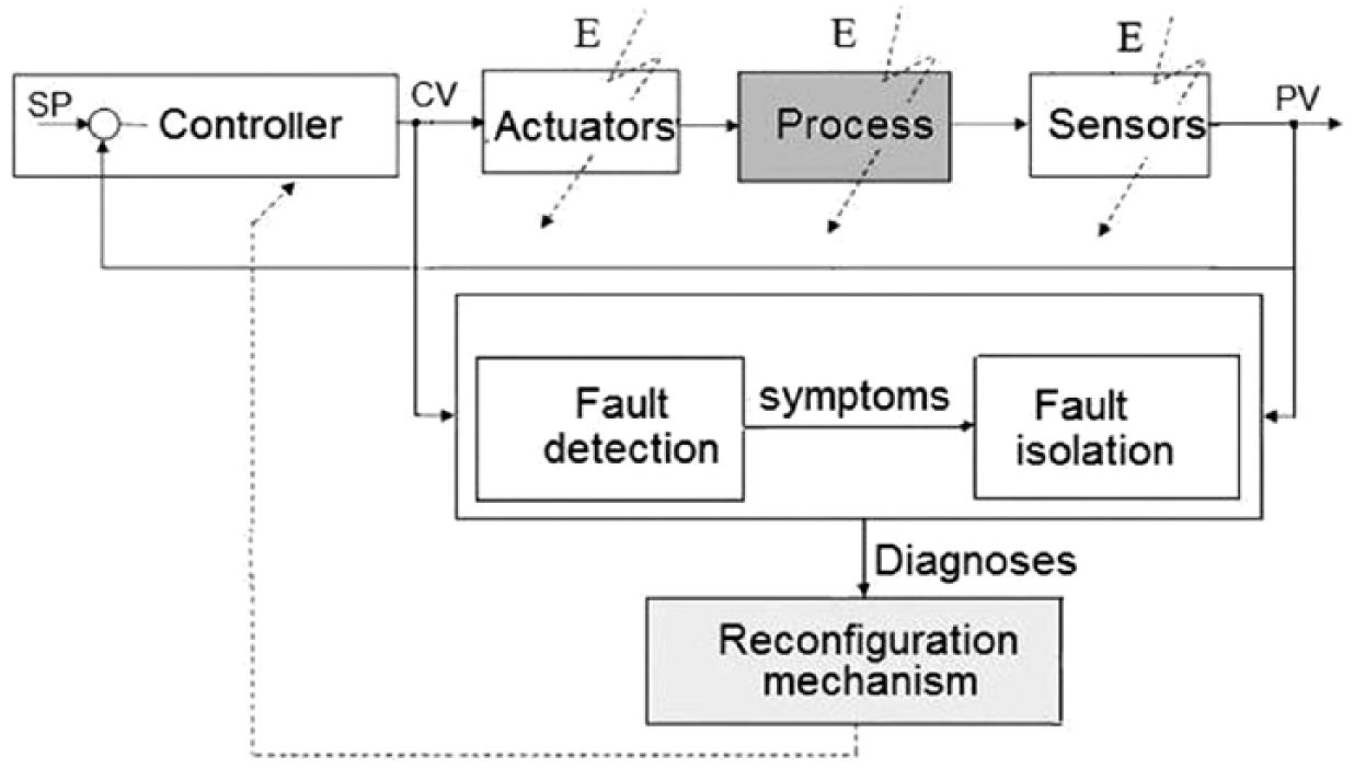
Operating principle of an active FTC system.
Generally, FTC systems can be divided into active (AFTC) and passive (PFTC) ones. In the PFTC concept, the system tolerates only some types of faults, those which were identified as the most critical at the design stage. A PTFC type of controller compensated the predicted fault without current information about the fault. The main characteristics of PFTC systems include sensitivity only to some types of faults, use of equipment redundancy and more conservative behaviour.
Due to an inability to change or increase the quantity of equipment by introducing equipment redundancy, the AFTC system type is used more often.5,8,9,16 Its characteristic feature is that it uses both equipment redundancy (if available) and analytical redundancy. 9 It helps such systems also tolerate the types of faults not predicted at the system design stage. The AFTC systems compensate the fault by selecting one of the previously designed control systems or by an online synthesis of a new control system ( Figure 1 ).19,23,24 Both concepts require using detection and identification of the fault location. An example of such a fault is presented in Blesa et al. 5 This type of control systems is characterized by applying analytical redundancy,5,8,9 using methods of fault detection and identifying its location, and accepting capacity reduction during the fault.16,24
Contemporary diagnostic systems are complex, dynamic and operate in a stochastic manner.9–13,17,18 When designing engineering diagnostic systems, one has to take into consideration a variety of structures and types and the possibility of applying different mathematical models to describe them.3,5,7,11,12,25 Moreover, knowledge of engineering methods, neural networks and fuzzy systems can be used for their modelling, as presented in some papers.11–13,17,18
When designing an FTC system, one should mainly focus on the fault tolerance of actuators and sensors. Owing to the FTC system, in case of a fault, the automation system adapts its structure to compensate for the impact of the fault.2,19 In particular, the measurement circuit can be, for example, replaced by a redundant measurement (using virtual sensors7,25). A change in the control system structure can also prove to be a good solution, for example, when replacing a three-element control in literatures1,4 with a one-element control, as proposed in Lindsley. 2
The level measurement in the steam drum can be falsified in a differential system, for example, due to a leakage at the joints or clogging of the signal tubes (as a result of mineral salts deposition). It should be remembered that water dissolves alkaline salts and silica in the whole pressure range. The boiler drum in the boiler process line separates steam from water and prevents capturing of saline water to the super-heater and turbine. The salt remaining in the boiler water has to be removed from the boiler drum on a continuous basis.
The operating ranges of differential pressure transducers are small, for example, the level measurement of 10 cm means only about 1 kPa, so any leakage in the signal tube can cause a significant measurement error. When applying two measurements, we can choose ‘one out of two’ and the diagnostic system should automatically identify which one is defective.
The basic measurement inaccuracy results from the following:
Errors caused by wrongly made reference condensing vessels
Errors caused by wrongly installed measurement system
Errors caused by poor thermal insulation that is supposed to ensure correct operation of the reference vessels
High fluctuations of static pressure
Measurement errors resulting from steam content under water level
Errors resulting from inaccuracy of the differential pressure transducer.
This is a reason for using the reliability and detected minor faults’ method of control of measuring tracks.
FTC systems have not been commonly applied in power engineering yet, but some works related to diagnostics and the safety of wind turbine operation can be observed; examples are described in literatures.5,7
Studies of the water-level control system in a steam drum using the FTC system for the measurement circuits as presented in the paper are original ideas, providing a new solution. The author also studied another type of power unit control system – a condensing turbine control system, which was implemented for practical use. The results of the studies are presented in Pawlak and colleagues.23,26,27
II. Control System for Boiler Drum–Level Water – Identification of Problems
A boiler drum is one of the most important process elements of a power boiler. A drum boiler comes with a process security system for the boiler. A steam drum is provided with a water gauge and diagnostic system, initiating the boiler shutdown when the level decreases or increases too much. As this is high-pressure equipment, the security systems have to be accepted by the Office for Technical Supervision, and the security system activating point has to comply with the water gauge glass. A binary signal from the water-level measurement is usually supplied to the security system. It can be corrected based on the temperature and pressure in the boiler drum or not corrected at all.
Besides the security system, a boiler comes with a water-level control system in the steam drum1,2,4 and a three-element control system, as presented in Figure 2 . To eliminate the control system’s faulty operation, three-element systems are used, and the additional feeds to the control system are signals from the flow transducers of steam (FD) and feed water (FW)
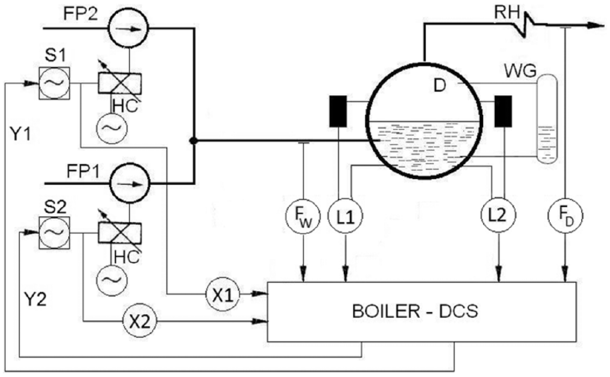
Conceptual diagram of the water-level control system in the steam drum.
The three-element structure ( Figure 2 ) clearly reflects the sense of water-level control in the drum, that is, to maintain balance between the water inflow and steam outflow. At the same time, the signal from the level sensor allows maintaining a constant level of the mixture. The controller determines the difference between the steam outflow and water inflow, which is then summed with the level control deviation.
Two level measurement systems can be distinguished in the control system presented in Figure 2 (L1 and L2). They use differential pressure transducers. The flow of the boiler feed water (FW) and the flow of steam supplied to the turbine (FD) provide additional correction signals for the control system. The boiler feed water is delivered by two feed water pumps (FP1 and FP2). Both pumps can satisfy 100% of the water demand, which means that during normal operation one pump is activated and the other one is a back-up pump. This kind of system is used in Polish 125-MW power units. When the boiler is operating under nominal steam parameters, the water flow is controlled by changing the pump’s rotational speed. The rotational speed is modified with hydrodynamic clutches. Signals on the position of the actuator which controls the clutch are sent to the control system.
An active FTC system concept will be presented for the previously described control system. Its role will be to detect faults of the measurement circuit’s parameters. Poor reading of the measurement values in the level control system can cause an unnecessary shutdown of a power boiler by a system of process locks. As we take into consideration a double-level measurement system using differential pressure transducers, the diagnostic system has to detect which measurement is wrong and switch the control system to the correct measurement.
Measurements taken by differential pressure transducers are the most popular method of measuring the level in the steam drums. This kind of transducer caters for a wide range of operating temperature and pressure values. It also enables correction of the measurement signal, accounting for a change in the boiler operation point and the liquid pressure value in particular.
The measurement is based on identifying the hydrostatic pressure exerted by a water column (height: h). Making an assumption simplifying the liquid density constant, the pressure clearly determines the liquid level. The level depends linearly on the pressure

where p is the measured pressure, g the gravitational acceleration, ρ the water density and h the liquid column.
In open tanks, it is sufficient to measure the overpressure, that is, the pressure value above the atmospheric pressure. In the case of a liquid measurement in closed tanks, the pressure value depends not only on the liquid column height but also on the pressure of gas under the water surface. It requires the use of differential pressure transducers.
A demonstrative diagram of hydrostatic measurements is presented in Figure 3 . The level against the stub pipe is measured (2). The h level is the current level value. Generally, the saturated steam pressure in the boiler drum is much higher than the atmospheric pressure. The density of the liquid and steam also constitute essential parameters of the measurement. That is why the measurement correction is necessary.
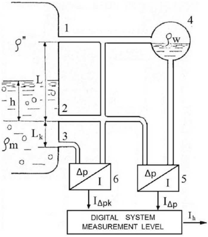
Measurement of the volumetric level with correction depending on the pressure.
A system measuring the volumetric level is an example of a corrective system, where a corrective transducer (6) connected to a water stub pipe (2) and an additional stub pipe (3) are used to identify the density of the steam–water mixture ( Figure 3 ).
Figure 3 presents the measurement method, taking into account the level correction and liquid density changes. Usually, reference tanks are used for measurements. Steam condenses in the top signal duct (1) due to low ambient temperature. The transducer (6), connected to the water (2) and auxiliary stub pipes (3), acts as a correction system. A cold vessel (4) containing condensate is connected to the stub pipe (1). The basic transducer (5) is connected to the reference vessel and the measurement stub pipe (2).
The measurement of the pressure difference between stub pipes (2) and (3) helps identify the actual water density in the tank ( ρm in (2))

where Δpk is the pressure difference, g the gravitational acceleration, ρw the water density, ρm the steam–water mixture density and Lk the distance between stub pipes (2) and (3) ( Figure 3 ).
When this value and the initial value of the basic transducer (5) are known, the h level of the steam–water mixture can be calculated (3)
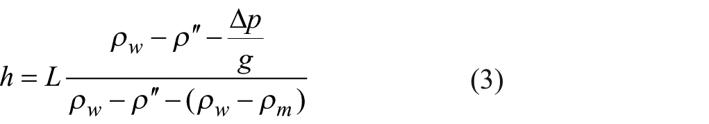
where Δp is the pressure difference, g the gravitational acceleration, ρw the water density, ρm the steam–water mixture density, ρ″ the water steam and l the distance between stub pipes (1) and (2).
ΔIΔpk and ΔIΔp are the output signals from differential pressure transducers, calculated according to Equations (4) and (5)


where Δp is the pressure difference; m = (In − Io)/Δpmax, and m is the factor slope characteristics; Io is the minimum value of the output currents of the transducer, In the nominal value of the output currents of the transducer and Δpmax the range transducer.
III. FTC System for a Boiler Drum Water-Level Control System – Presentation of the Approach
A. Diagnostic system
Three basic procedures can be distinguished in an active FTC system (according to Figure 4 ): detection, fault isolation and the reconfiguration mechanism of the control system. Each procedure should be executed as a separate task in the control system diagnostic algorithm.5,9,19,24,27
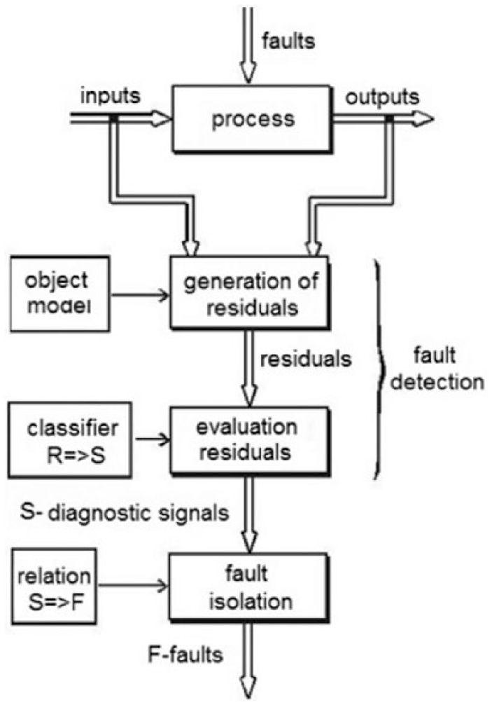
Diagnostic scheme using process models.
The basic goal of the diagnostic system is to improve the reliability of the automation system. This means striving for the highest ability to detect and differentiate faults possible, while maintaining the lowest possible costs.3,19
Partial models of the controlled object are used in the diagnostic systems, for instance, to diagnose5,19 measurement circuits. Figure 4 presents the scheme of such a system.
B. Fault detection
Interim models of the process, functioning as virtual sensors, were applied for fault detection.6,8 This helped with analytical redundancy, to detect the measurement circuit fault in question. The basic purpose of the fault detection algorithm is to be able to detect all faults. This means that a collection of diagnostic signals sensitive to a specific fault had to be designed. A decision was made to develop three partial process models of the process for the feed control, recreating the following values: water level in the boiler drum, feed water flow and steam consumption by the turbines, according to formulas (6), (7) and (8)


where L1, L2 are the level of steam–water mixture in the boiler drum measured by two redundant transducers, FW is the feed water mass flow, FD is the steam mass flow and X is the measured control signal of X1 or X2 hydrokinetic clutch actuator, depending on which pump is working.
The dynamics of the changes in the level of the steam–water mixture in a boiler drum can be described by two transmittances presented in Figure 5 .1,2
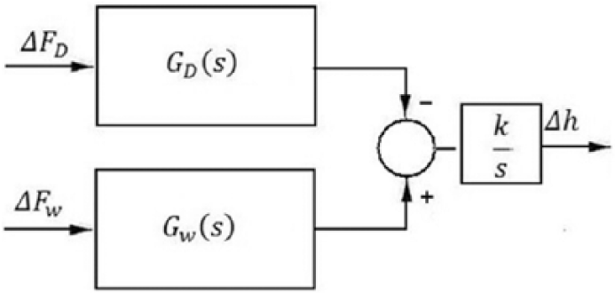
Dynamic model of the water level in the boiler drum.
The boiler drum, as an object of level control with an input in the forms of the feed water supply and steam feeding into the turbine, can be described as a high-order inertia object with integration.
Models (6) and (7) have the same configuration as each other, the only difference being which transducer is checked: L1 or L2. The level model (L = L1 or L2), depending on the feed water inflow, was obtained with Strejc’s method. The Strejc model with and without the time delay is used as a model of dynamics of linear plants. 28 Strejc’s method obtains a model of form (9) from the features of a step response
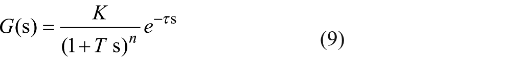
where K is the gain factor, T the inertial time, n the inertial order and τ the time delay.
The value of the steam flow to the turbine was identified and then the response to the increased supply of feed water was checked. The following transmittance model (10) was obtained for the nominal conditions of a 125-MW unit operation
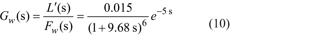
where L′ is the derivative of the water level in the steam drum and FW the water mass flow to the boiler.
The second step to recreating the complete model of the level in the boiler drum involved identifying the level derivative, which depends on the steam consumption by the turbine. The task was much more difficult due to the non-minimum phase nature of the object. The best obtained model was a sixth-order model, with a delay of 3 s. The model was approximated to the continuous order 3 model and then decomposed, using a partial fraction method, into the sum of the first-order inertia and the oscillating object, to obtain the following at the end (equation (11))
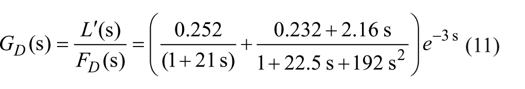
where L′ is the derivative of the water level in the boiler drum and FD the steam mass flow to the turbine.
The last stage to recreate the value of the water level was to add the outputs of the obtained level derivative models and the integration of the signals.
When comparing both inputs in to the system, it has to be emphasised that the values ΔFW (s) and ΔFD (s) are mass flows of the feed water and water steam, respectively. The assumption facilitates further designs for the feed control system, as the primary goal of such a system is to maintain equilibrium between the steam mass flow to the turbine and the water flow to the boiler drum.
The value of the residuum is calculated as an absolute value based on the difference between the results calculated by models and the results of reading levels from measurements L1 and L2.
The residuum mean in time is calculated to reduce its value in a fault-free condition and to reduce the detection level. The residuum created based on the partial process models, where the real measurements of the level and flow are taken into account, is sensitive to the fault of all measurement circuits, except for the feedback signal from the pump control. Then it is necessary to develop a different model to ensure that X1 and X2 feedback signals are detectable and to allow faults to be distinguished. That is why another model of the boiler feed water flow has been identified.
A model of the water flow through the pump, depending on the control signal, was developed (the model linearity and the superposition principle were applied) (12). The best pump identification results were obtained for a model with continuous time of about 2 s which was manually adjusted to better recreate the flows. The following formula was obtained
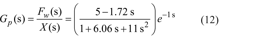
where FW is the feed water flow and X the pump control signals from Figure 2 .
The obtained relationships helped identify the values of the level and flow based on the control signals and actual measurements. The obtained models identify the residua used for detection of the measurement circuit faults ( Table 1 ).
Specification of residua.
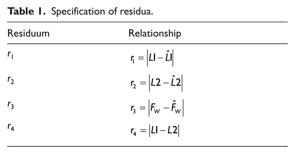
Due to the increased ability to distinguish faults, an additional residuum comparing the redundant-level measurements was attached to the diagnostic system.
C. Fault isolation
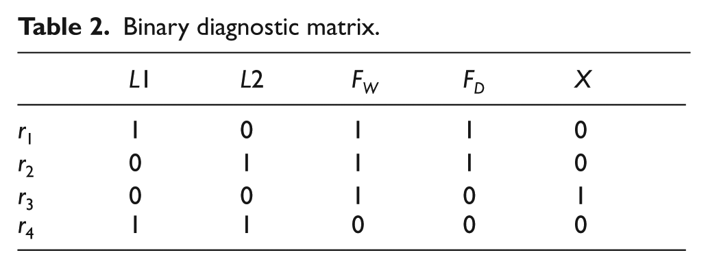
A binary diagnostic matrix was applied to the algorithm identifying the fault location. The conducted analysis helped identify the binary diagnostic matrix corresponding to the measurement circuit fault and diagnostic signals based on the analysis of residua r1, r2, r3 and r4 ( Table 2 ).
Binary diagnostic matrix.
The value of signal X comes from the actuator controlling the currently working pump. The system must be designed to identify the working pump. The algorithm for identifying the fault location is not able to determine which pump is at fault. The problem was solved upon reconfiguration of the control system by stating that ‘if one of the pump systems was subject to a fault, it is the system for the currently working pump’.
The location identification is based on parallel reasoning.10,24 It means that the fault can be detected when the values of the diagnostic signals correspond to its signature (columns in Table 2 ).
The form of the binary diagnostic matrix presented above actually excluded the possibility of detecting multiple faults. The phenomenon is rare and highly unlikely. The occurrence of any two faults causes activity of all diagnostic signals. If the reasoning is applied, no fault will be identified. In an automation system (Distributed Control Systems (DCS)/Supervisory Control and Data Acquisition (SCADA)), such a status (condition) should be considered in the alarms. It would not be a problem in a conventional process diagnostic system. However, in the FTC type of control system, multiple structure reconfiguration would cause shutdown of the controlled system. Then it would be reasonable to leave the decision about the response to such a system condition to the operator.
D. Reconfiguration of the control system
The last stage of designing a control system resistant to measurement circuit faults involves identification of the back-up structures that the system switches to when the fault location is identified.
When designing a control system resistant to the measurement circuit fault, the group of the possible operating conditions (W) of the system when each fault occurs has to be identified (13)

There are the following methods for measurement circuit fault tolerance in the case of the reference system:14,20,24,27 equipment redundancy of the measurement circuit, analytical redundancy of the measurement circuit and application of equivalent variables.
Table 3 presents a short description of the possible modification of the system operation under each measurement circuit fault.
Reconfiguration of the control system at the measurement circuit fault.
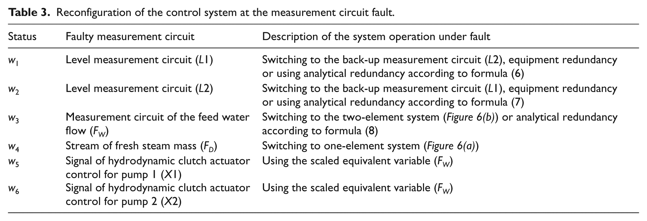
The control system uses the measurements of the steam and water flow. If the measurements are wrong, they should not partake in controlling the water level in the steam drum. Two possibilities of fault tolerance were considered – switching the flow measurement to a virtual measurement or a change in the control system structure. It is possible to apply the flow models after obtaining a sufficiently precise model. The second option was used in the studied control system. Although it can result in poorer control quality factors, in particular at great fluctuations of steam consumption by the turbine, the method guarantees safe operation of the control system.
Both control systems – the two-element and one-element – after reconfiguration are presented in Figure 6 . The easiest reconfiguration method is switching the control systems working in parallel. However, the discrepancy between the control signals determined with a three-element ( Figure 2 ) and a one-element or two-element ( Figure 6 ) controller causes a problem. A sudden change in the applied control signal causes an ‘impact’. In extreme cases, it can cause an emergency condition in a system. That is why an impact-free system for control systems switching is required. This is achieved by setting the proportional–integral (PI) controllers (6 in Figure 6 ) to monitoring mode and setting the adjustment offset to zero Lo = L => ε = 0 during normal operation.
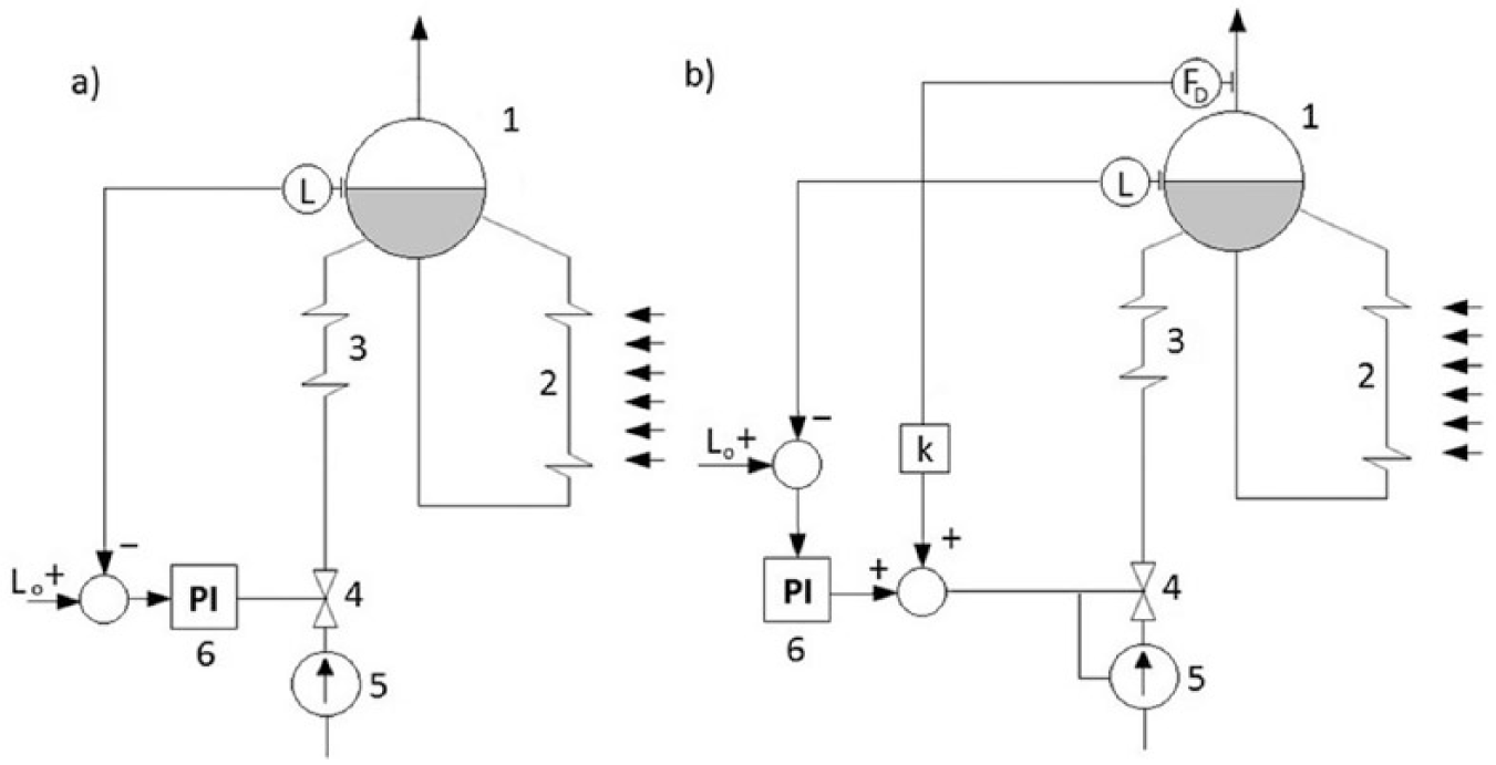
Diagrams of a control system reconfigured after detecting the sensor: (a) FD – stream of fresh steam and (b) FW – stream of feed water.
IV. Results of Modelling
A. Tests of models
The responses of the described models (10) and (11) to abrupt changes in the volume of water flowing to the boiler drums and the volume of steam taken by the turbine are presented in Figure 7 .
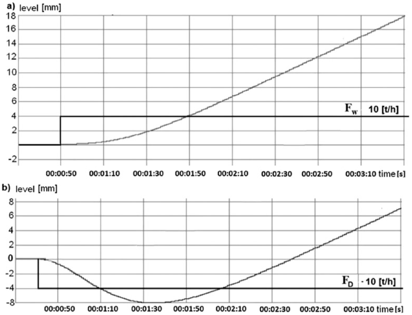
Change in the water level in the boiler steam drum: (a) feed water increase and (b) decrease in steam consumption.
Under abrupt changes in the volume of water flowing to the boiler, a significant delay caused by insufficient heating of the feed water can be observed. Despite the fact that more water flows to the tank, the level is maintained with relative stability and can even decrease in extreme cases. This is caused by condensation of some of the water bubbles as a result of the temperature decrease.
The dynamic model of changes in the boiler drum level has another input. Steam intake to the turbine is the signal. The input can be treated as interference because its value depends on the momentary load of the power unit. 2
When the boiler drum is under thermodynamic balance and the level of the steam–water mixture is stable, an increase in the steam demand from the turbine raises the level of the steam–water mixture. It is caused by a decrease in the steam pressure. Consequently, the intensity of steam bubble formation increases and so does the level. This happens despite the fact that the water weight in the tank decreases. Too high an increase in the steam–water mixture level may result in an intake of highly salinated water into the turbine. After some time, the level of the mixture no longer goes up and starts to decrease continuously. A momentary increase in the level at a higher steam intake may cause irregularities in the controller operation. 2
The operation of the identified model (8) against the actual measurement is presented in Figure 8 .
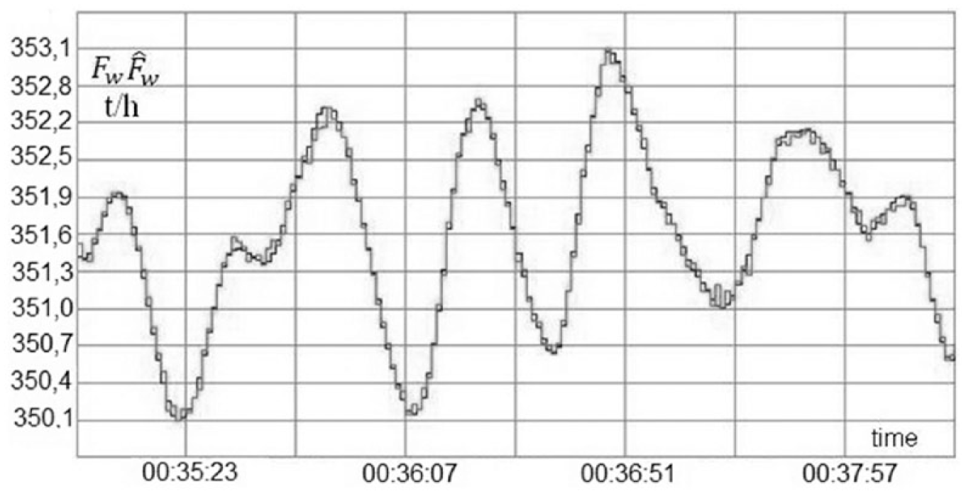
Comparison of Gp transmittance model with actual measurements.
The obtained model (8) can be used as a redundant measurement of the water flow. It is sensitive to the fault of the measurement circuits X1 or X2 and faults of the water flow measurement circuit.
The first stage of tests on the control system involved validation of models (6), (7) and (8) by comparing them with the actual values read from measurement transducers during normal operation without any faults (Figures 9–11 show examples of waveform residuals r1, r2, r3). At this stage, the values of the detection thresholds were also identified.
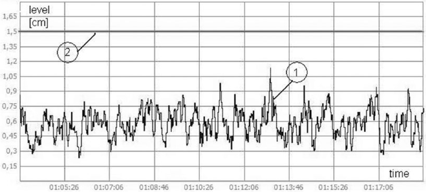
Waveform of r1.
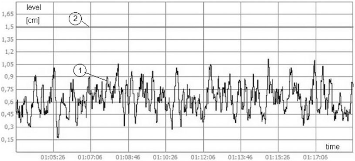
Waveform of residuum r2.
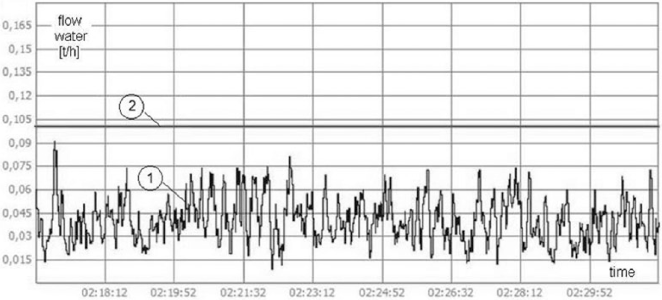
Waveform of residuum r3.
Qualities of adjustment in the water-level control system in the boiler drum were also checked to obtain data for comparisons. The maximum deviations caused by operation interference during normal operation of the power unit amounted to 10 mm, which means that a steady state was achieved ( Figure 12 ).
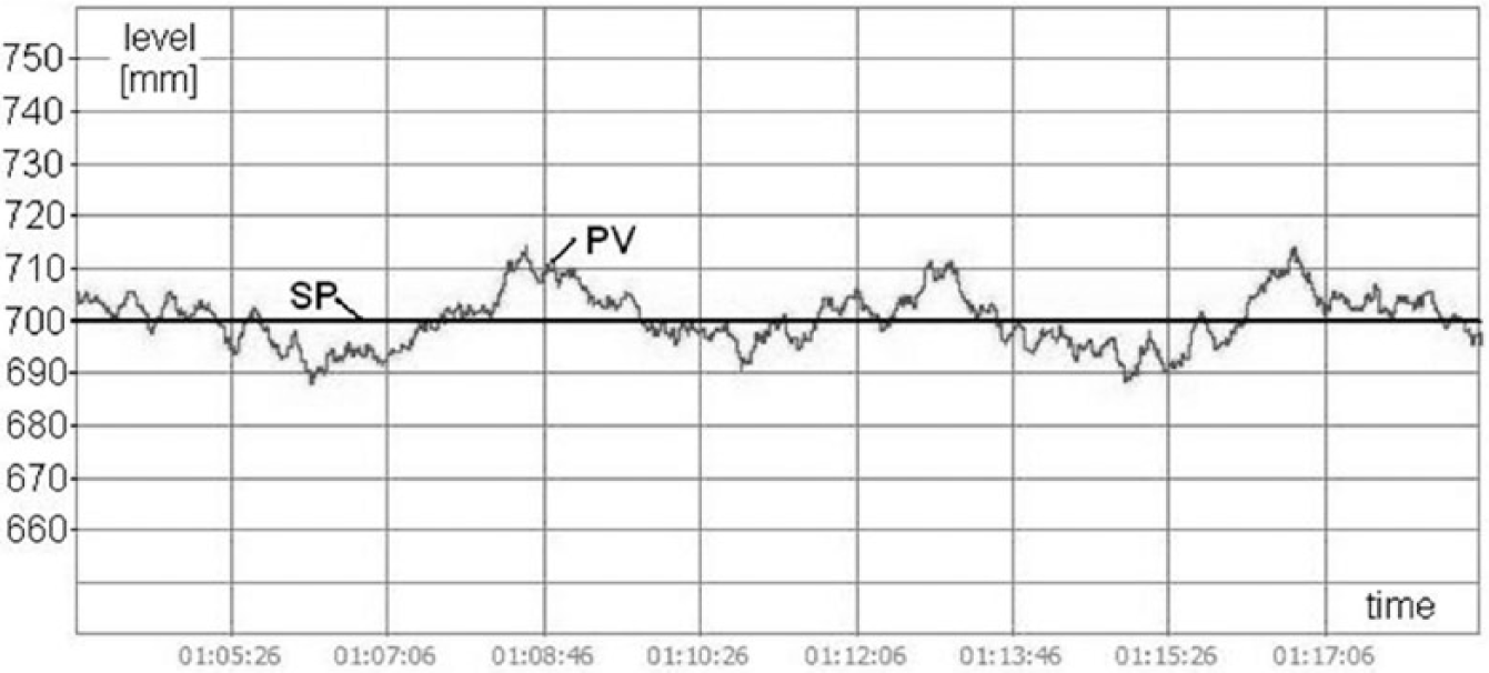
Waveform of water-level adjustment in the boiler drum in a faultless condition.
B. Tests of diagnostic system
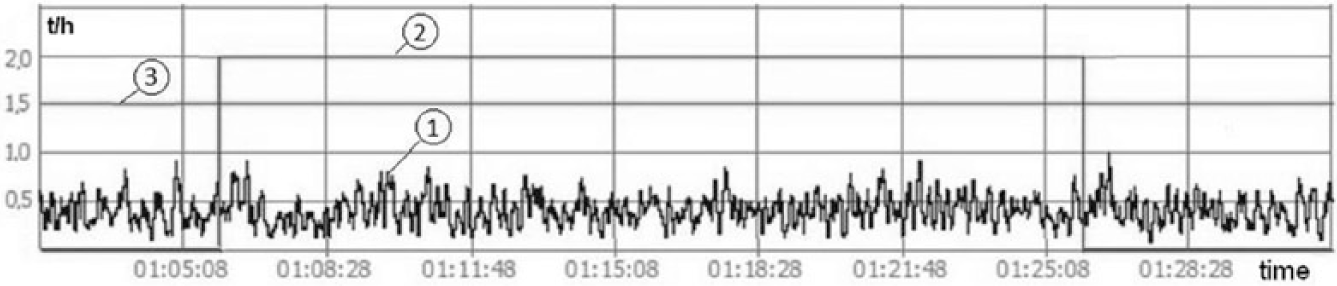
Within the tests of detection procedures, the sensitivity of each residuum to the faults of a specific measurement circuit was tested. For example, the simulation of the water level L1 measurement circuit fault is presented in Figure 13 . A parametric fault of the L1 measurement circuit was introduced in the FTC system tests. The simulated fault presents a common case of partial clogging of the pressure transducer pulse tube (6 and 7 in Figure 3 ), which may disappear after time.
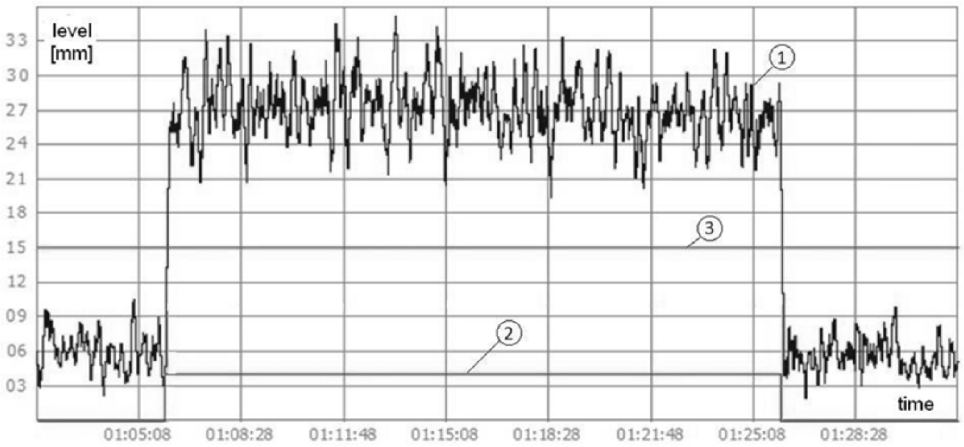
Simulation of L1 measurement circuit fault.
A fairly stable deviation occurs between the actual measurement and the virtual measurement. As can be seen in the waveforms in Figure 13 , the diagnostic signal responds almost instantly. In both cases, the value of the residuum exceeds the threshold value after as little as 3 s. A very quick change in the value of the diagnostic signal to zero when the fault disappears is another advantage.
According to the results, the third residuum (r3) is completely resistant to L1 fault. Neither the fault occurrence nor its decay affects the value of the diagnostic signal ( Figure 14 ).
Waveform of residuum r3 under L1 fault.
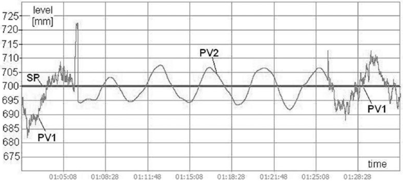
The level values according to the physical and virtual sensors are presented more precisely in Figure 15 . Rapid fluctuations of the measurement signals caused by the fault occurrence and decay can be observed. At the same time, the signal recreated by the model maintains a value similar to the set point (SP).
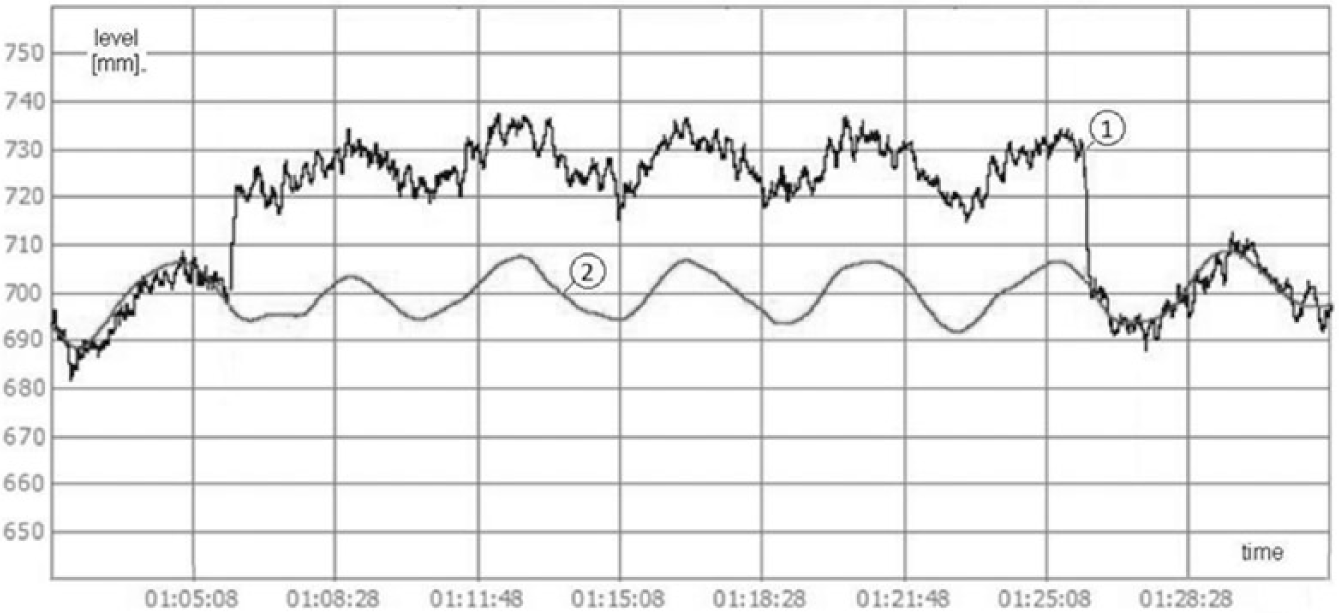
Waveform of the water-level value according to the physical sensor and model (1).
Despite the fault, the control system works normally ( Figure 16 ). The momentary peak during the structure reconfiguration is caused by a delay in the diagnostics against the fault introduction. Nevertheless, it does not disturb the system operation and immediately after reconfiguration the system returns to the previously set level. The adjustment deviation does not exceed the value of 10 mm. Similarly, when the interference stops, a second peak of the water-level value can be observed but is quickly eliminated.
Waveform of the water-level adjustment in the boiler drum under fault L1.
V. Conclusion – Discussion
The presented solution is the first system of its kind acquired for a water-level control system in a power boiler drum. FTC systems have not been commonly applied in power engineering yet, but some works related to diagnostics and safety of the wind turbines’ operation can be observed; examples are described in literatures.5,7
The studies of the water-level control system in a steam drum, using the FTC system for the measurement circuits, as presented in the paper are original and provide a new solution. The author also studied another type of power unit control system – a condensing turbine control system, which was implemented in practical use. The results of the studies are presented in literatures.13,26,27 The system presented in the paper 16 was tested and implemented successfully. The system has been implemented and operates in a power plant, bringing measurable economic and environmental benefits. It inspired the idea of creating a similar system for the water-level control system.
Such a control system has been studied for many years, as presented in Alouani et al. 1 and Chakraborty et al. 4 The studies focused on optimization and modernization of the control algorithm structure. In these systems, there were often unused diagnostic measurement circuits or expensive and not always effective instances of hardware redundancy. Control system faults are among the most common causes of industrial process faults. They are presented in papers4,14–16,19,21 for industrial facilities’ control systems. The solution described in this article analyses a special case whose application improves reliability of a power unit operation, which is of high importance when attempting to achieve more efficient power generation.
All control systems made for the study fulfil their role in a satisfactory way, which results in a minor deviation in the water-level adjustment in the boiler drum. The tests confirmed the efficiency of the fault detection algorithm. The created models of the water level and flows proved to be successful. Under a no-fault condition of the facility, there were no errors in the diagnoses and the values of all residua were below the detection thresholds. This was achieved despite a high value of measurement noises. The residua helped detect minor faults (e.g. those with values of less than 25 mm for parametric faults of the L1 level measurement, as presented in the example).
Power units are highly complicated thermal and mechanical structures, composed of many devices with a different reserve degree. The essential power unit devices (boiler, turbine and generator) are singular, while auxiliary devices (e.g. fans, coal mills, pumps and control systems) have an actual or additional reserve (standby; i.e. equipment or information structural surplus) to increase the reliability of their operation. Contemporary power units have to be equipped with a number of digital automation and security systems.
Footnotes
Funding
The author(s) received no financial support for the research, authorship and/or publication of this article.