
Abstract
In this proposal, microcontroller-based energy flow control was designed in order to effectively and efficiently enable the use of energy sources in a hybrid energy generation system including wind, solar, and hydrogen energy. It was assumed that the hybrid energy generation system is dynamic during the design of the microcontroller-based energy flow control. A wind–solar energy generation system was determined as the base load power plant. Depending on the demand, the battery group and fuel cell were activated effectively. If an energy surplus occurred, it was stored in battery groups and transformed into hydrogen energy via a hydrogen generator simultaneously. In addition to providing energy sustainability, a constant active status of the energy storage group was prevented and the physical life of the group was prolonged by means of the microcontroller-based control system. If consumer demand could not be met by the main energy sources including wind and solar energy, the battery groups and fuel cell were activated and provided the energy sustainability. After a certain level of charge was reached in the battery group, it was deactivated via the control system in order to prevent unnecessary use of energy. By means of the microcontroller-based control system, the usage of energy generated with the hybrid energy generation system was analysed according to its efficiency.
I. Introduction
Energy, an indispensable element of our daily lives, maintains its importance in the economic and social structures of countries. Also, the share of electrical energy in the sector is increasing every day.1–5 Rapidly increasing energy demand, decreasing fossil fuel resources, and the need to generate clean energy have directed the economy to renewable energy resources. Rapid population growth accompanied by irregular urbanization and increase in energy demand accompanied by industrialization have brought about environmental problems.6–13
It is well known that energy resources such as wind and sun have changeable characteristics due to different climatic conditions. 14 Therefore, storage systems gain special importance because of the fluctuations in the wind speed or solar radiation. So, the operation of off-grid systems should be accompanied by energy storage systems in order to provide energy sustainability.15–19 In this study, fuel cells and a battery group were used in order to implement a dynamic hybrid energy generating system and provide energy sustainability. Also, the energy flow was controlled by means of a microcontroller to ensure the efficient usage of the energy.
It is notable that hybrid energy resources have been studied together with hydrogen energy in scientific researches. In those researches, beside optimization studies, application-oriented studies have also taken place. Maleki and Pourfayaz 20 conducted a cost analysis for a hybrid system including wind power, solar power, and a diesel generator supported by fuel cells and a battery group for energy storage. Niknam et al. 21 examined the uncertainties in demand for electrical energy and market prices. They modelled the random variable input using Weibull and normal distribution functions. They conducted calculations of the total energy and cost using the Gram–Charlier method for the day-ahead market. These optimization studies were conducted with different methods and their results were presented. On the other hand, there are relatively few application-oriented studies that include setting up a system.
Eroğlu et al. 22 worked on a mobile house application of a photovoltaic–wind and fuel battery hybrid energy system. In this research, solar energy and wind energy were utilized as the primary resources while the fuel battery was utilized as the secondary resource. Wind energy, solar energy, and a battery were connected at a single DC busbar while the fuel cell was designed to be activated as needed. The fuel cell was activated when the energy from other resources was inadequate, with a switching system at inverter entry. In the mobile house energy implementation, hydrogen was acquired with an electrolysis machine and stored in hydrogen tanks under compression at high pressure. Sustainability was provided through the electricity from the combustion of hydrogen from the hydrogen fuel cell when the wind and solar energy was insufficient. They proved the usability of different renewable energy resources at the same time in off-grid applications.
The basic difference between this research and the study conducted by Eroğlu et al. 22 is that in this research, all of the energy resources (solar, wind, fuel battery, and battery group) have been designed to supply the energy requested in a dynamic way. Moreover, if the energy from the sun and wind exceeds demand by customers, it is used to store hydrogen gas in hydrogen tanks via a battery and/or electrolyser.
Dursun and Kılıç 23 worked on the control of an off-grid hybrid energy generation system. Three different energy resources were used in the system, namely photovoltaic panels, wind turbines, and a proton exchange membrane fuel cell (PEMFC). In this system, the photovoltaic panels and wind turbine were used as the main energy resources. The battery group was also connected directly to the DC busbar with these resources. The fuel cell was utilized as a substitute power resource. In this research, the battery group was connected to the DC busbar without any switching element. However, in our proposed study, the increase in the lifespan of the battery group was targeted by means of the battery group’s activation and deactivation feature. Thereby, in our proposal, the battery group was utilized as an energy resource.
In another study regarding off-grid hybrid energy generating system implemented on a mobile house, Suha Yazici et al. 2 utilized the fuel cell as a secondary resource. The study was designed to activate the fuel cell in case the energy demand could not be met by the battery. In our study, the energy need was met temporarily by means of the designed control algorithm. Moreover, the proposed system has the feature that it can be used not only off-grid but also on-grid via a control system if all energy resources are inadequate.
Sopian et al. 24 also acquired hydrogen gas for use in a fuel cell with the help of energy generated by the sun and wind. They stored the hydrogen gas in hydrogen tanks under compression at high pressure. In a similar research conducted by Chávez-Ramírez et al., 25 consumers in Mexico were supplied with a parallel connection to a battery group from three off-grid energy resources, namely wind, solar, and a fuel cell.
This study differs from the other studies with respect to its temporary response to demand. Furthermore, energy resources are used efficiently. In this study, the energy flow generated by the hybrid system is controlled and monitored by the control system. The energy flow arrangement is acquired with the information from solar panels, wind turbines, and fuel battery using an algorithm designed in a micro-monitor-based control system. Besides offering energy sustainability, the control system aims to prolong the lifetime of gel batteries used as energy storage by preventing their constant activation. The energy demanded by the consumer is primarily supplied by wind and solar energy. At the times when demand cannot be met, the required energy is provided by the energy stored in the battery group and fuel cell. The battery is deactivated by means of the controller system when the battery level has reached a certain fill factor or there is no energy requirement. Thus, the unnecessary usage of energy is avoided.
Furthermore, since the setup costs of these types of systems are high, the detection of possible savings for customers is important. In order to limit consumption, 9-W power-LED fluorescent bulbs are used instead of 18-W tube fluorescent bulbs.
II. Materials and Methods
In this section, the design and establishment of the control group and the components of the battery-group-supported hybrid energy generation system including solar energy, wind energy, and a fuel cell are explained. Moreover, the information about the micro-monitor-based control unit and energy flow control is presented in detail.
A. The components and features of the hybrid energy generation system comprising solar energy, wind energy, fuel cell, and battery group
The components of the hybrid energy generating system including solar energy, wind energy, a fuel cell, and a battery group were three 24-V 190-W monocrystalline solar panels, a 600-W three-phase stable magnet with a synchronous generator wind turbine that can rotate 360° according to the direction of the wind, a 500-W PEMFC, and six 12-V gel batteries (gelled electrolyte lead-acid) which are 100 Ah. The battery groups are used to store the energy surplus and to provide energy sustainability for the cases in which the system cannot generate energy.
Electrical energy generated by the hybrid power generation system is checked by the microcontroller-based hybrid controller unit, and the voltage values of the power are periodically recorded by computer. Since the output voltages of the electrical energy produced from the energy resources comprising wind, solar, and the fuel cell are unbalanced, power is supplied through a DC-DC converter. While the input voltages of DC-DC converters are within the range of 18–72 V, the output voltages are fixed at 24 V. Besides, electrical energy generated by the hybrid power generation system is converted to AC power with the help of a 3-kW sinusoidal DC-AC inverter and then becomes the electrical energy to meet consumer demand.
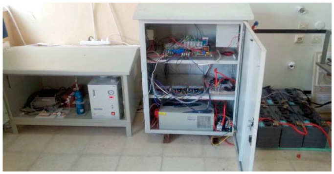
On the other hand, it is possible to continuously monitor the energy generated by the hybrid power generation system consisting of wind, solar, and a fuel cell. The acquired data are saved every 10 s in an Excel spreadsheet via a software program. The assembled hybrid power supply system is shown in Figure 1 . The connection scheme and operating model of the components of the hybrid power generation system are illustrated in Figure 2 while the operating logic and energy flow structure of the assembled and battery-powered hybrid power supply system are illustrated in Figure 3 .

General view of a battery-powered hybrid energy supply system consisting of wind, solar, and fuel cell
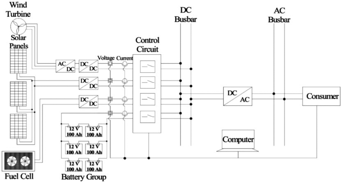
Connection scheme and operating model of the components of the hybrid power supply system
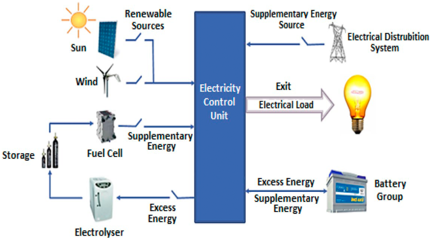
Operating logic and energy flow structure of the assembled and battery-powered hybrid energy system
The technical features of the components used in the hybrid power supply system are detailed below.
Wind turbine
The wind turbine, one of the basic components of the hybrid energy generating system, has 600 W of nominal power and three-phase 24-V AC. The activation speed of the wind turbine is 2.5 m/s and its maximum operating speed is 25 m/s. The wind turbine has a permanent-magnet generator that carries out braking at a speed of 25 m/s. The rotor wing of the wind turbine has a radius of 1.2 m and the rotor speed is controlled mechanically. The turbine’s whole body, tail, hub, and so on are constructed from aluminium composite containing 13.6% magnesium and it is resistant against corrosion and light, weighing only 6 kg. These turbines have a working life of 20 years and their wings are constructed from full injection carbon-fibre-reinforced plastic (CFRP) material in order to reach the lowest vibration level.
Photovoltaic panel
Because of the crucial role played by solar radiation in the production of energy from the sun, it must be at the right level to be capable of energy production. As is known, the operational cost of a solar power generation system is considerably lower than that of other systems. As a result of recent technological improvements, there has been notable progress in both solar panel power and productivity.
In this study, three 190-W monocrystalline panels with 72 cells and 18% cell productivity are used. These panels have an operational voltage of 24-V DC, a maximum operating voltage of 37.08, a maximum power current of 5.12 A, and a breaking current of 5.54 A.
Fuel cell
Fuel cells have high power density. Also, they are capable of starting rapidly and suitable for fluctuating power output. Thus, PEMFCs are used for transportation and portable systems. 26 Today’s PEMFCs are developed as an alternative for internal combustion engines in the automotive industry and used as hybrid technologies.
The operating voltage of a PEFC 500-W fuel cell is 20–36 V and its nominal operating voltage is 24-V DC. Its nominal operating power is 21 A and its productivity is approximately 50%. The fuel cell used in this work consumes 6.3 L/min of hydrogen at full performance and is supposed to provide hydrogen to the entrance of this cell at a pressure of 0.5–0.6 bar. Furthermore, the purity of the hydrogen should be a minimum of 99.95%. The fuel cell is a simple, useful, and secure design with high power density and light weight. There is no need for trigger tension to activate this fuel cell. It comprised a cell stack, fans, control card, and electromagnetic valves.
The connection points and the structure of the fuel cell are shown in Figure 4 . They are as follows:
Connection port to the control circuit (anode);
Connection port to the load and control circuit (cathode);
Hydrogen entrance point;
Hydrogen exhaust outlet;
Fans (in order to prevent overheating during the operation of the fuel cell);
Hydrogen exhaust outlet pipe from the solenoid valve;
Hydrogen connection pipe;
Solenoid valve (solenoid outlet valve for the discharge of the exhaust gas and water after reaction).
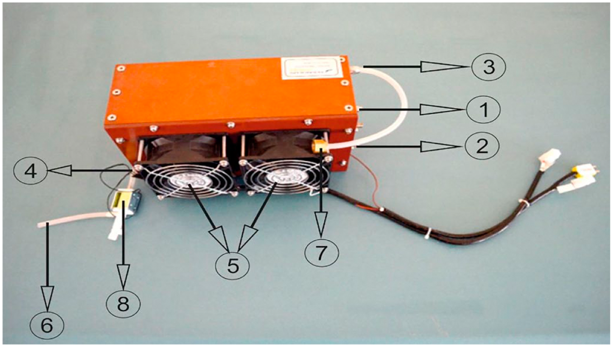
PEFC 500 W fuel cell
It is necessary to perform some checks and preparations before activating the fuel cell:
It is necessary to check whether the power and data cables are connected properly.
The fuel cell should be used under the ambient temperature and humidity conditions specified in its manual.
In the case of the presence of gases that could affect the activation of the fuel cell in the surrounding air, such as nitric oxide, sulphur dioxide, methane, propane, esters, and components of cosmetics and perfume, the fuel cell must not be activated.
After the checks mentioned above have been completed, the fuel cell can be activated safely. First, the hydrogen valve providing the gas transition to the fuel cell is opened. Then, the solenoid valve exhausts the waste gases in the tube. After the operating pressure has reached 0.5 bar, a voltage of 33–36 V is provided in the unloaded fuel cell. The fuel cell is ready to be loaded 2 s after its activation. At this stage, the fuel cell is not loaded with more than 60% of its nominal power. Then, the fuel cell generates 24 V and 500 W of power under normal circumstances. To deactivate the fuel cell, first the loads are decreased and then the hydrogen valve is turned off. Fuel cell energy generating system is shown in Figure 5 . The technical specifications of the PEFC-500 fuel cell are listed in Table 1 .
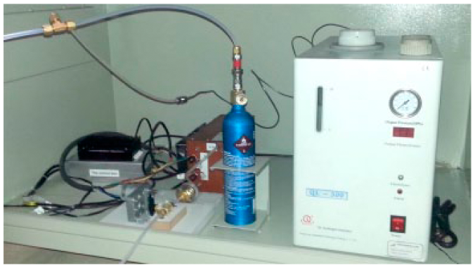
Fuel cell energy generating system
The technical specifications of the PEFC-500 fuel cell.
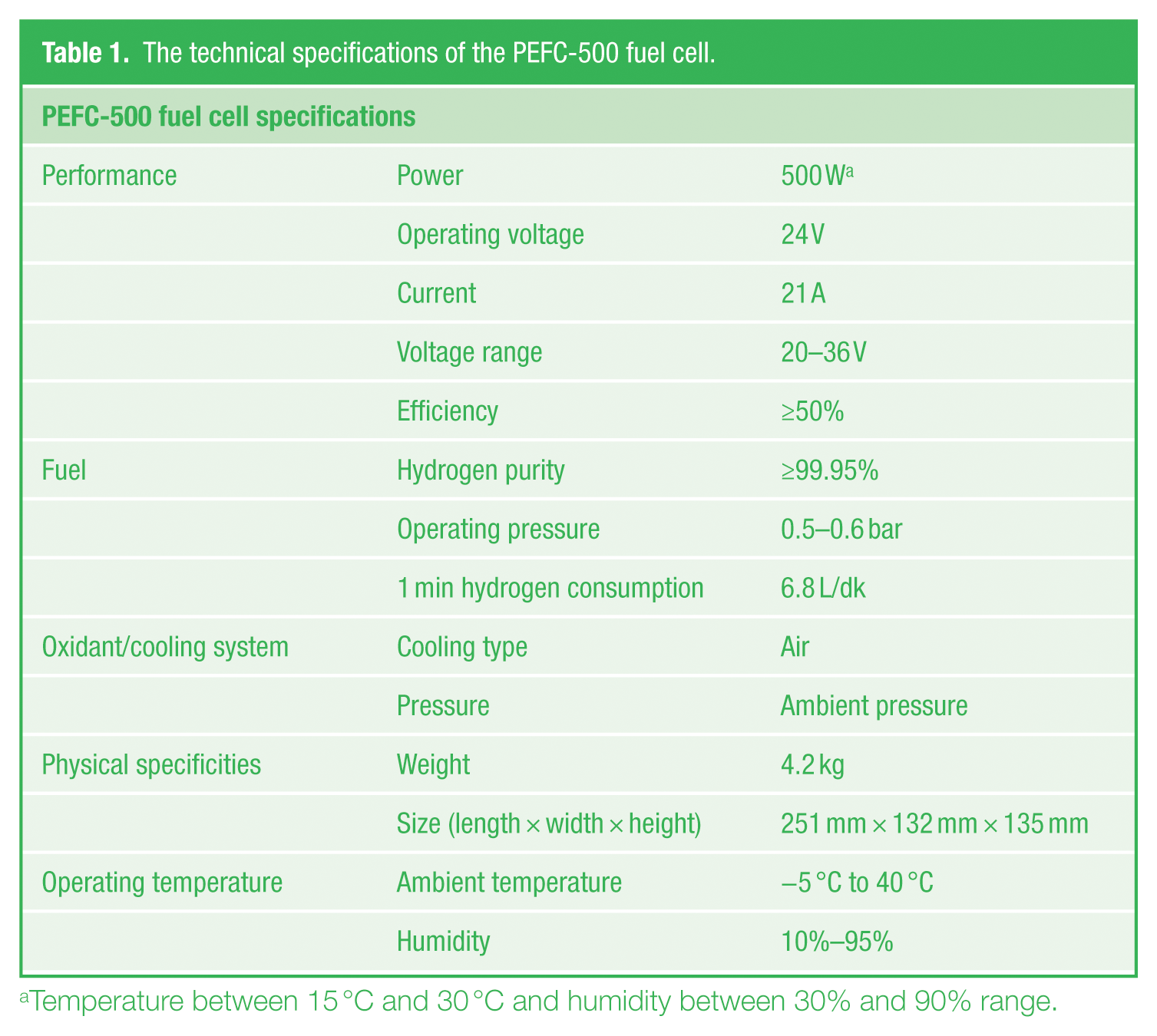
Temperature between 15 °C and 30 °C and humidity between 30% and 90% range.
Battery group
The energy required to illuminate the laboratories was supplied by batteries prior to their connection to the electricity grid when there was no energy generated from the wind, sun, or fuel cell in the hybrid power generation system. Calculations were made based on the assumption that the battery group was full and all groups of lamps were active in the laboratories. The lighting system of the laboratories was set up with 4X18-W double parabolic armatures as seen in Figure 6 . In this study, it is presumed that the laboratory will be lit for an average of 8 h. Four 18-W tube fluorescent lamps were replaced with three 9-W power LED fluorescent lamps in the two laboratories with the aim of using the battery group and other energy resources efficiently.
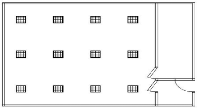
The layout of armatures in the laboratory
Total Power = The number of lamps × The power of lamp

The total energy consumed by armatures with 8 h/day activation

The capacities of the batteries are measured in ampere-hours. Accordingly, the capacity of the battery can be determined from the ratio of daily energy consumption to the voltage. Since the system is 24 V, the voltage rating was taken as 24 V to determine the capacity of the battery

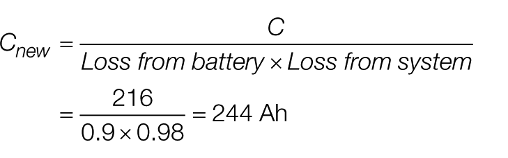
Depending on the loss of energy arising from the battery itself, the convertor, and the system, preferring the battery group was not correct according to the results obtained from the formula above. The new capacity of the battery was calculated as 244 Ah taking into consideration the loss of 10% of the energy from the battery and convertor and the loss of 2% of the energy from the system
In total, 10% of the battery capacity is allocated as the safety margin of the battery. So, taking 90% of the battery capacity into account, the necessary capacity was calculated as 271 Ah in order to provide energy for the system for 8 h (non-stop)

As a result of these calculations, a 24-V 100-Ah battery group was formed by connecting two 12-V 100-Ah batteries in series. A 24-V 300-Ah battery group was formed by connecting three of these series groups in parallel.
B. Design and strategy of the control system
The energy generated from the wind turbine, solar panel, and fuel cell in the hybrid energy system is collected in the busbar with a 24-V stable DC voltage. At the same time, the battery group is connected to the DC busbar. Then, the stable DC voltage is converted to AC by means of the inverter so that it is in line with the consumers’ operating voltage.
The data flow regarding the power generated by the solar panels, wind turbines, and fuel cells is arranged with the microcontroller-based energy flow control system. The power LED fluorescent lamps used to light the laboratory are assumed to be loads to be met by the hybrid power generation system. The wind turbine and solar panels in the hybrid energy generation system are considered as the main sources of power. The energy required by the load is compared to the energy generated by the wind turbines and solar panels. If the energy required by the load is met by these two sources of energy, the fuel cell and battery group are not needed.
In case the energy required by the load cannot be met by the wind turbine and solar panels, the fuel cell is activated. If the fuel cell is also inadequate, the battery group provides the energy required by the load. The surplus of energy is utilized efficiently. The energy surplus is stored in the batteries depending on the fill factor of the battery group (if the rate is under 95%). If the batteries are completely full, the surplus energy feeds the hydrogen generator and generates hydrogen. The hydrogen gas produced is stored in the hydrogen tube. Thus, the surplus energy is not used unnecessarily.
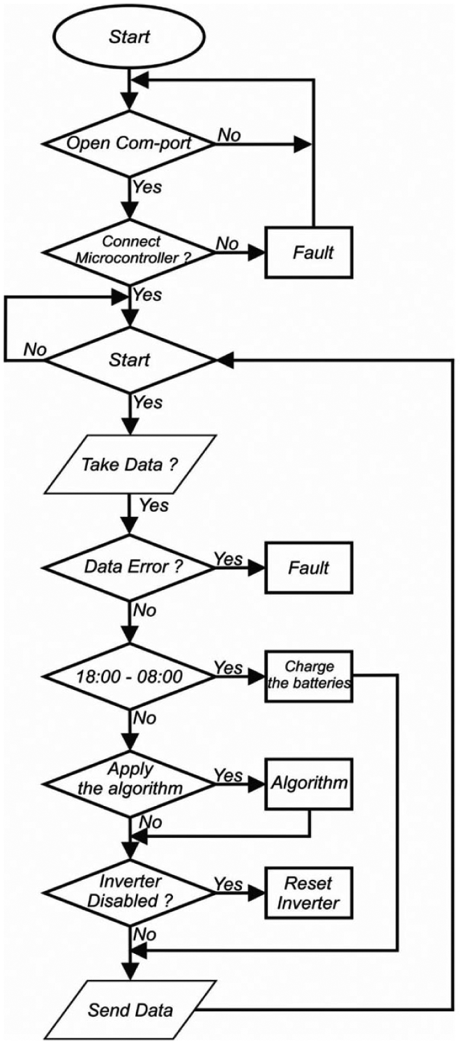
The algorithm indicating the working order according to the amount of power required and produced in the hybrid power generation system is shown in Figure 7 . The control algorithm employed to use the power efficiently is illustrated in Figure 8 .
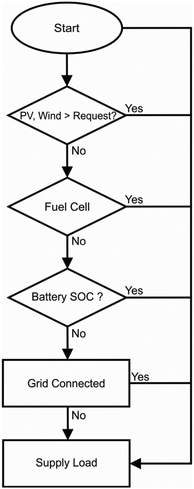
The algorithm indicating the working order according to the amount of power required and produced in the hybrid power generating system
The control algorithm
Establishment of the control system
After developing the working algorithm for the hybrid power generation system, the system was set up. A panel involving circuit components to provide control of the energy flow was designed. The upper part of the panel was sectioned for the control circuit, the middle part was sectioned for the DC-DC convertors, and the lower part was sectioned for the DC-AC convertor. It was planned that only the fuel cell, hydrogen tube, and hydrogen generator would be on the second panel.
The connection of cables coming from the solar panels, wind turbine, and fuel cells to the inverters is made in the box. The anodes of the wind turbines, solar panels, and fuel cells coming from the DC-DC convertor and the anode of the battery are connected to the DC busbar (+) with a 50-A diode in order to prevent the backflow of energy when the battery is charged from the grid.
The anodes of the power supplies passing through the current meter in current–voltage measuring circuit are connected in the DC busbar and then connected to the anode of the inverter. The cathodes of the wind turbines, solar panels, and fuel cell coming from the DC-DC convertor and the cathode of the battery process the activation and deactivation according to the orders received from the microcontroller.
The connected circuits for the energy flow control and assemblaged energy control system in the box can be seen in Figure 9 .
Control unit of the hybrid power generation system
C. Software interface of energy flow control system
The command sequence of the programmable logic controller was created in the frame of the determined control algorithm after controlling the energy flow generated and consumed in the hybrid power generating system. A software application was developed for monitoring the system. A screenshot of the software can be seen in Figure 10 .
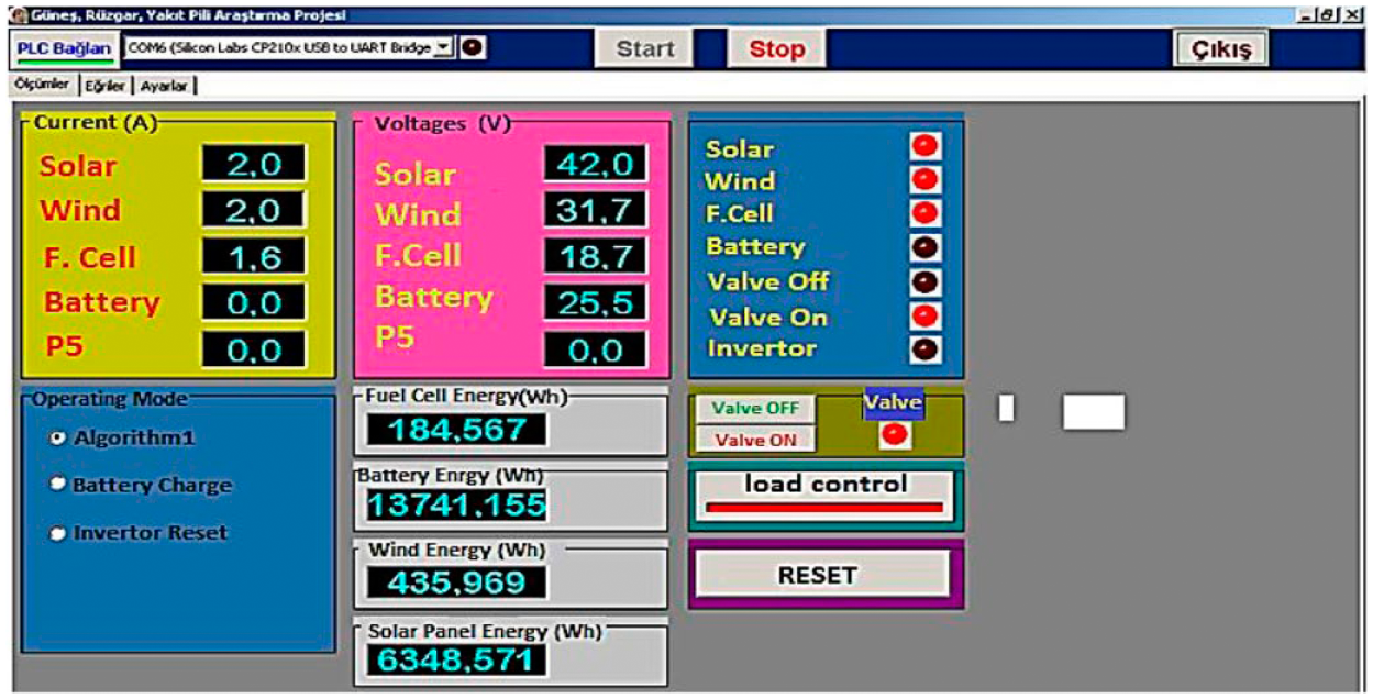
Screen shot of hybrid power control system
III. Experimental Results and Discussion
The energy-generation performance of the energy sources in off-grid wind and solar energy–based hybrid power generation systems differs according to the topography of the system location and meteorological conditions.
Renewable energy sources are thought to be crucial in the upcoming years according to studies in the literature. In particular, it is envisaged that the principle of generating electrical energy regionally and its consumption in the region where it is generated will be implemented in the near future. Therefore, it is foreseen that the generation of electric energy by local producers for their own consumption will become more important in addition to interconnected electric energy systems. Provided that the costs of hydrogen technologies decrease and their accessibility for consumers increases, local producers may generate electrical energy for their own consumption. In addition to hydrogen technology, solar power systems may also play a significant role. On the other hand, the situation is not the same for wind power since it is not applicable in every condition.
The primary purpose of this study was to provide a continuous off-grid energy supply through a control system designed for an installed hybrid power generation system. Therefore, a smart grid model was developed by integrating renewable power generation systems in the grid.
Taking into consideration the fact that the solar and wind power of the hybrid power generation system are natural energy resources, it can clearly be stated that the power generated by the hybrid power generating system depends on meteorological factors. Therefore, an energy management strategy is necessary in order to control the system elements to achieve the best results and effective usage of the generated energy. The purpose of the energy control system is to provide energy without interruption while providing energy efficiency of the battery group and lowering the activation and deactivation frequency of the fuel cell. It is assumed that less frequent activation and deactivation of the substitute power units of the hybrid power generation system, including the fuel cell and battery group, will lead to longer lifetimes of these units. The main factors affecting the energy flow management strategy in hybrid energy generation systems are the amount of power generated by the renewable energy systems and the battery group fill factor.
A. Energy-generation data of battery-group-supported hybrid power generation system
In this study, the data of the energy generated by the hybrid energy generation system and energy consumed were logged every 10 s between 08:00 and 18:00 from 1 August 2014 to 31 December 2014 by computer. The system was designed for charging the batteries and generating hydrogen gas by hydrogen generator after 18:00.
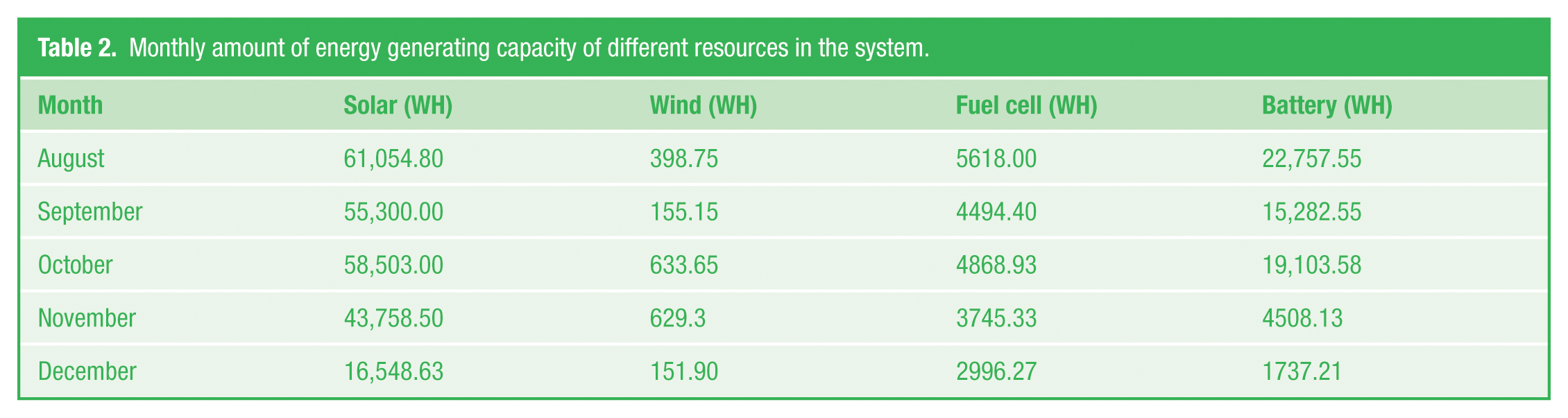
The frequency of 10 s was determined in order to provide sensible traceability of the system. However, this process led to the acquisition of a huge amount of data, which made the evaluation process difficult. After the consolidation of relevant data, the monthly total of energy generated by the energy resources was calculated. The monthly data of the energy generated by these resources are shown in Table 2 . Moreover, in Figure 11 , these values are shown graphically.
Monthly amount of energy generating capacity of different resources in the system.
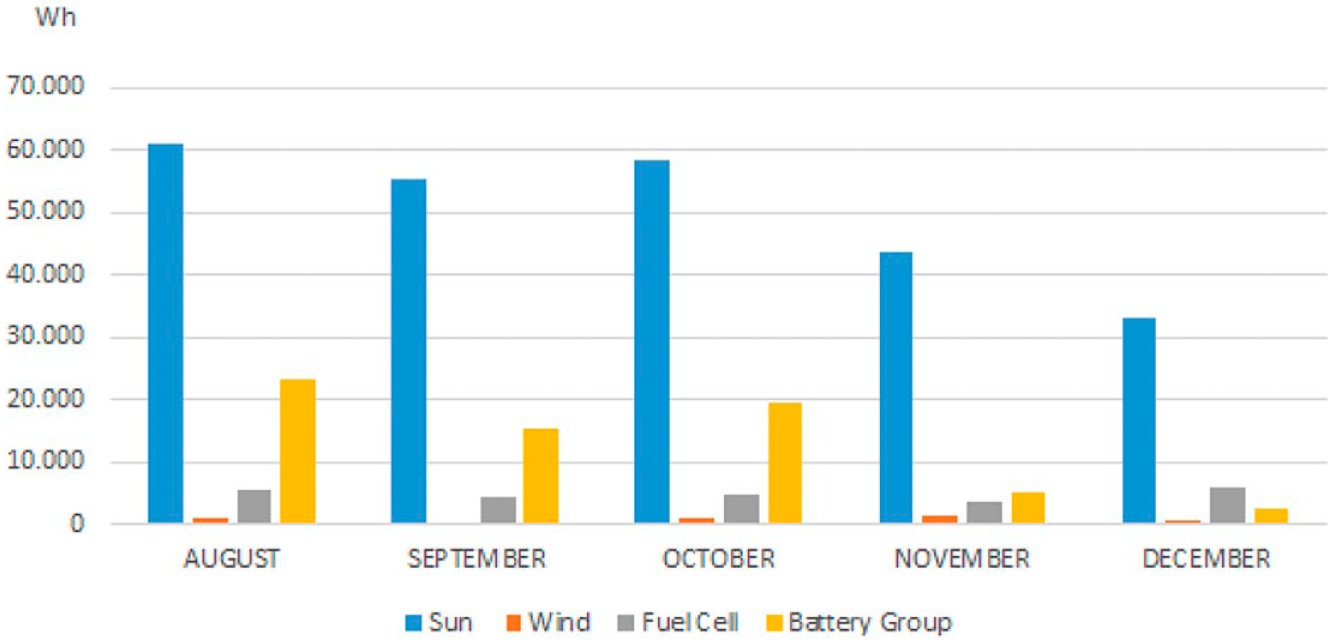
Bar chart for monthly amount of energy generating capacity of different resources in the system
Depending on its location and height, the low wind potential of the turbines is reflected in the amount of energy generated by them. The wind turbines could not generate any energy on some days during the study.
During the design of the hybrid energy generation system, an aim was to achieve sustainability of the energy flow with the help of fuel cell activation according to the algorithm developed for the periods in which the solar panels and wind turbine could not generate power or could generate lower levels of power than demanded.
Besides, the quick activation and deactivation of energy sources is crucial on account of the dynamic (depending on the generated and consumed power) design of the energy flow. Thus, 24-V DC 30-A power relays with a reaction time of 15 ms are used first in the switching system of the control unit. The optimal sustainability of the energy flow is attained by switchover of MOSFETs by the switching circuit, which has a reaction time of 1.5 µs.
According to the working principle of the system, in cases in which the wind turbine and solar panels could not generate power, the fuel cell power generation unit was activated and met the power demand if there was a sufficient amount of hydrogen gas. The control system sent signals with very short frequencies to activate and deactivate the relevant power resources and this caused some problems with the fuel cell. Depending on the inconsistent amount of power generated by the wind turbine and solar panels, the control unit sent signals to the fuel cell to activate and deactivate suddenly. In order to eliminate the risk of shortening the fuel cell’s lifetime, the algorithm was revised so that the fuel cell would be activated only if wind or solar power could not be generated. Under this circumstance, when the fuel cell was activated, it met the energy demand until the hydrogen gas was completely used up. In the cases in which the fuel cell was completely used up at a time when the solar panels and wind turbines could not generate power, the battery group was activated.
The HS 760 hydrogen tube used in the fuel cell system can store 500 L of hydrogen gas if it is loaded under a pressure of 10 bar. In line with its control algorithm, the fuel cell was usually activated in the early mornings and evenings after 17:00 depending on the lack of solar power and wind power.
B. Comparison of consumption and generation data of hybrid energy generation system
Electrical energy generated by the solar panels and wind turbines met the electricity need of the armatures directly. If there was a power surplus, the battery groups stored the power like a consumer.
An electricity meter was connected to the lamps line in order to determine the total consumption of electrical power. The amount of power generated, consumed, stored, and lost in the hybrid power generation system is illustrated in Figure 12 .
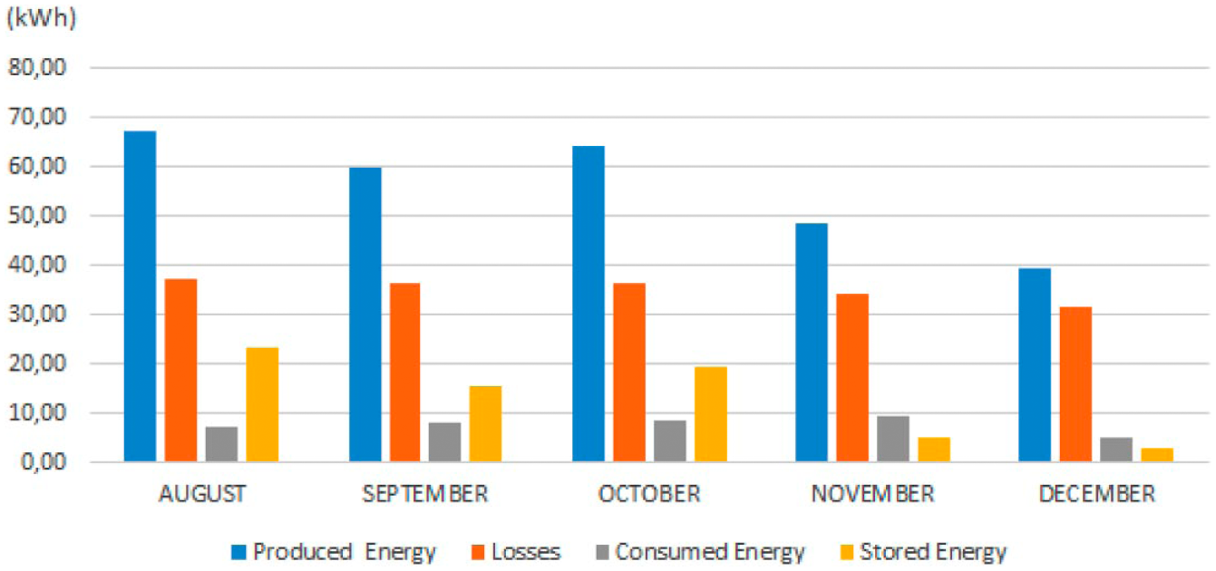
Amount of power generated, consumed, stored, and lost in the hybrid power generating system
Taking into consideration the power loss encountered in the circuit elements (including the DC-DC converter, AC-DC inverter, control circuit elements, and connection conductor) used in the hybrid power generation and distribution system, the effective usage rate of the power generated was determined. The approximate energy loss rates were calculated according to catalogue information and the average operating times of the DC-DC convertors and AC-DC inverters of the hybrid power generation system. Under normal operating circumstances, it is necessary that the measurement devices will be used on the entry ends and discharge ends of the power converters and inverters in order to calculate the power loss. However, in this study, the energy loss of the relevant convertors and inverters was calculated approximately using catalogue information because the budget was insufficient to afford the relevant measurement devices.
The data for the generation, consumption, storage, and loss of power of the hybrid power generation system are given graphically in Figure 12 . The effective usage rate of the power generated after deducting the energy loss was calculated for each month. Depending on this calculation, August 2014 was determined as the month in which the generated energy was utilized at the highest rate (48.61%). The monthly efficiency rate of the effectively used power generated by the hybrid power generation system is illustrated graphically in Figure 13 .
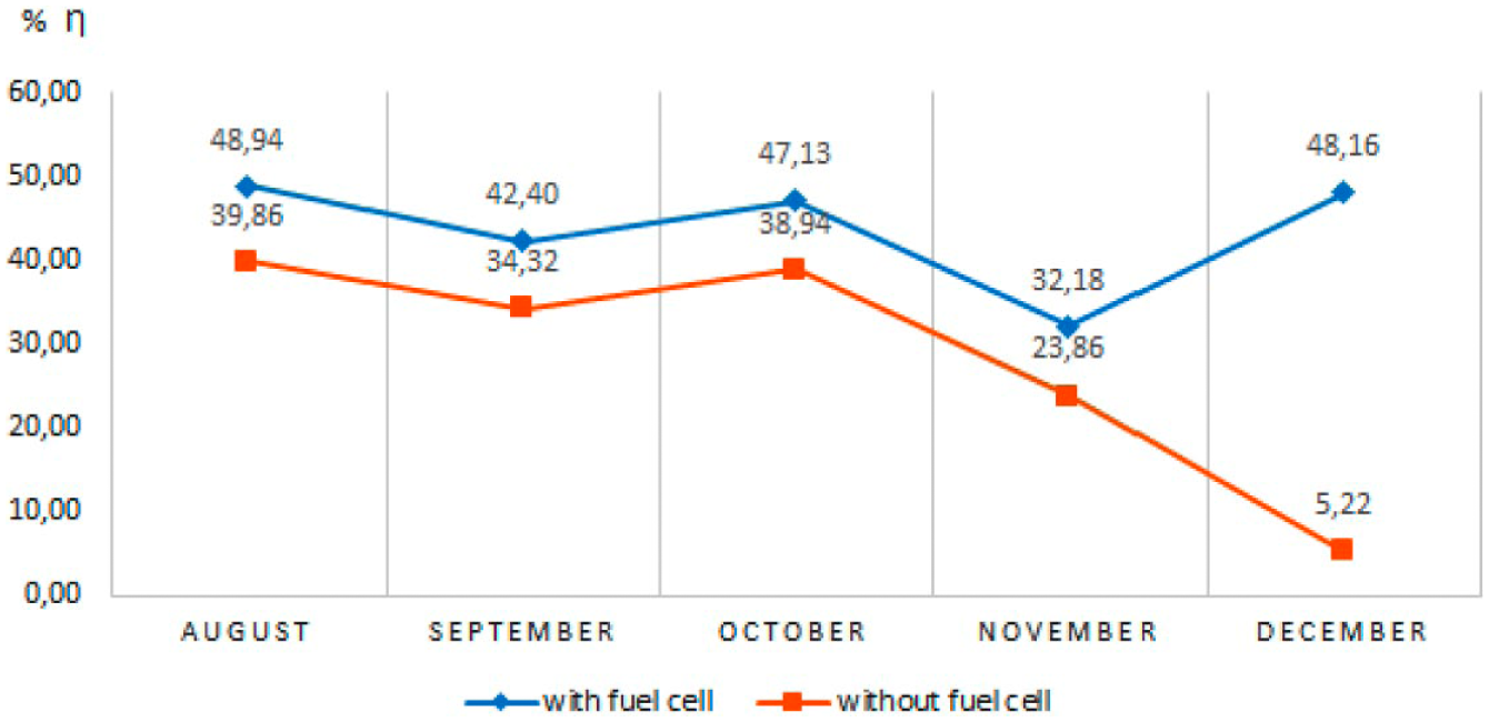
Efficiency rate of effectively used power which was generated by hybrid power generating system by months
In a hybrid energy generation system without a fuel cell, the efficiency would be lower because of the lack of ability to store the energy. The monthly efficiency rates of power generated by the hybrid power generation system without a fuel cell are illustrated graphically in Figure 13 . In this case, the energy surplus will be wasted when the battery capacity is full, so the fuel cell is used as a power resource and storage unit at the same time in this study.
IV. Conclusion
In the context of this study, solar and wind power, which were utilized as the primary energy sources, are not continuous sources, and therefore the total amount of energy produced by the hybrid production system is known to be lower in means of working times compared with controlled power production sources. After all, power produced by solar panels and wind turbines is not able to meet the demands of the energy load continuously. Accordingly, a spare energy source is necessary to provide an uninterrupted energy supply. This source should be able to function without relying on meteorological shifts and geographical conditions. A battery group and/or fuel cells may be considered as the most suitable spare energy systems for hybrid systems that are not fitted with a distribution system as they are controllable sources.
This study covers two different energy management strategies, namely, a hybrid power production system that is not fitted with a distribution system and a hybrid power production system that may be integrated into a distribution system. An uninterrupted energy flow is provided by means of this management strategy. The fuel cell process and frequency was controlled and minimized with the control algorithm. As a result, it is intended that the useful life of fuel cells will be extended. Also, excess electricity produced by the solar panels and wind turbines is efficiently stored in rechargeable batteries. In addition, excess energy is stored in tubes by producing hydrogen with electrolysers when the batteries are recharged. Variables such as the start-up order and frequency of energy sources are continuously evaluated and activated with this control algorithm. As a result of these actions, the efficiency of energy usage is 48.60% in the hybrid energy production system. Also, more detailed and different studies may be carried out with various data analyses in the case of long-term operations with power analysers and other power sources integrated into hybrid power production systems.
Footnotes
Funding
This research has been supported by grant number 113E310 from The Scientific and Technological Research Council of Turkey (TUBİTAK).