
Abstract
In this study, an electronic, mechanical and software system, where the weight measurements of eggs can be performed dynamically, is developed. As the speed is an important factor in the production sector, it is of significant importance that the manufactured products be weighed in a rapid and correct manner. For this reason, systems where the products are dynamically weighed are developed. However, as the products are weighed while they are moving in dynamic weighing systems, undesired disturbing effects occur on the measurement signal. The product weights must be measured at required speeds by eliminating this disturbing effect. Dynamic weighing is performed using a load cell. A digital signal processing–based card has been developed to measure the signal received from the load cell and to send it to the computer. The eggs are weighed while they are moving as they roll over the load cell. A program has been developed using the LabVIEW program to receive, filter and analyze the data read and sent to the computer by digital signal processing. In addition, the configuration adjustments of the integrated analog-to-digital converter that reads data from the load cell can also be performed thanks to this program.
I. Introduction
Today, digital signal processing (DSP) is widely used in the industry in real-time systems, and it has become an important subject in the area of electrical-electronics engineering as well. 1 Recently, rapid and accurate weighing of products has become of great importance to the manufacturing sector. Static weighing is based on fixing the product on the weighing platform to determine its weight. However, static weighing may not be suitable for some applications, and it may be more economical to weigh the objects while they are moving. 2 In order to achieve the required speeds, the products have to be weighed while they are moving. On the other hand, mechanical vibrations have a disruptive effect in systems that are capable of weighing moving objects.3,4 This disruptive effect varies depending on the moving speed of the system and the weight of the object. 5 Today, load cells are used for weighing in such applications. Load cells have an oscillatory attenuation response and they need time for the weighing signal to settle down. It is necessary to use advanced noise reduction techniques in order to reduce the response of load cells and such noises originating from environmental effects.6,7 In dynamic weighing systems, the intrinsic oscillations of the load cell combined with the low-frequency disturbance occurring due to the vibrations in the system make the measurement signal quite difficult to process. 4 It is considerably difficult to separate this disruptive effect originating from the vibrations in the system from the measurement signal. The most frequently used method to correct the response of the system is filtering the weighing signal. However, an important problem related to the signal processing in weighing systems is to design a filter that has a linear phase response and a short transient state at the same time. 8
In the literature, there are several studies on various techniques for dynamic weighing systems. Jafaripanah et al. 9 investigated analog adaptive techniques for dynamic load cell compensation. Piskorowski and Barcinski 7 designed a time-varying continuous-time filter to compensate the response of the load cell. In another study, a fuzzy logic estimator was used as the filter of the dynamic weighing system. 10 Another application area of the dynamic weighing systems is the weighing of vehicles when they are moving. These systems named as weigh-in-motion. Stokes examined the weigh-in-motion system in his study. The following is stated as the reasons for using these systems: Preserve the infrastructure, Increase safety, Save taxpayers’ Money, Deter overloading, Reduce traffic disruption and Collect Valuable Data. 11 Jacob et al. 12 elaborated the problems associated with overloaded vehicles and the potential of weigh-in-motion systems. Liljencrantz et al. 13 implemented a weigh-in-motion system in railways. Niedźwiecki and Wasilewski 2 studied adaptive filter applications for dynamic weighing of vehicles.
In this study, an electronic and mechanical system was designed in which products can be weighed in motion. With the developed computer program, digital filter design and analysis of the results can be realized easily. This paper is organized as follows: section II presents the electronic and mechanical system design. Section III describes the developed data acquisition and filter design software. Section IV shows the experimental weighing data and filter results. The final section explains the conclusions and survey results of this study.
II. System Design
The designed system is composed of an electronic and a mechanical part. Electronic weighing system is made of a DSP-based card and the software of this card. Mechanic system is designed to allow the weighing of the products while they move on the load cell platform.
A. Electronic design
A DSP-based electronic card is designed to amplify and measure the analog signal from the load cell and convert it into a digital signal. The block diagram of the system is given in Figure 1 . The signal from the load cell is initially amplified and converted into a digital signal by a Δ∑ analog-to-digital converter (ADC). Then, the digitized signal is processed using Sinc filter and then read by the DSP over the SPI serial communication interface. Δ∑ ADCs consist of a modulator and a digital Sinc filter. The digital filter defines the gain characteristics of the ADC and the passband characteristics of the converter. A Sinc filter has a linear phase response and it can remove all components on a given cutoff frequency without being affected by low frequencies.
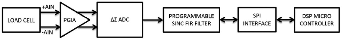
Electronic measurement system block diagram
B. Mechanical design
The dynamic weighing system presented in Figure 2 is built to weigh the products while they are moving. In the mechanical system developed, the eggs that are required to be weighed roll and pass over the load cell platform. The motor that provides the movement of the system is driven with an inverter. In this way, the products can be passed over the load cell platform at the speeds required. Hence, the product to be weighed is not stopped and weighed while it is in motion and the desired weighing speeds are obtained.
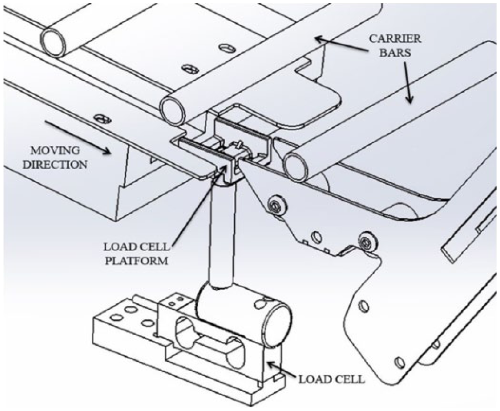
Mechanical dynamic weighing system
III. Software
A LabVIEW-based computer program has been prepared to receive data from the dynamic weight measurement system, to change the ADC settings and to process signals. The program consists of two main tabs. The first tab includes a graphical window where the calibration, ADC settings and received data can be graphically monitored and the data can be saved in a file. In this tab, it is possible to perform loaded (100 g) and unloaded calibrations of the load cell and to determine the gains. In the ADC settings, various settings such as the gain, sampling frequency and filtering options of the integrated ADC can be adjusted. It is possible to monitor the ADC and weight values from the graphical window in real time and to save these data in a text file where required. Data collection tab is given in Figure 3 .
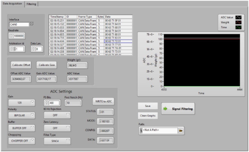
Data acquisition tab
In the second tab, gathered weight data can be filtered using various filters and its results can be analyzed. Filtering tab is given in Figure 4 . After required adjustments are made by selecting the tab of the filter to be applied, it is possible to filter the weight data with this filter. Weight data acquired as a result of the data collection and the data acquired as a result of the filtering of this data can also be examined graphically.
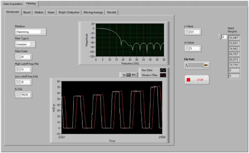
Filtering tab
In order to perform a better analysis of the results of the filters applied, a simple method which determines the weight where the egg is stable based on the filtered weight values is applied.
In this method
Δ: variations of weights;
t: measurement time;
m: number of weights measured in a stability range;
n: stability range.
As can be understood from Figure 5 as well, in order to determine the stable weight of the weighed object, the difference between the previous reading and the reading at that moment should be less than n value and consecutive readings of m value satisfying this condition should be obtained from the system.
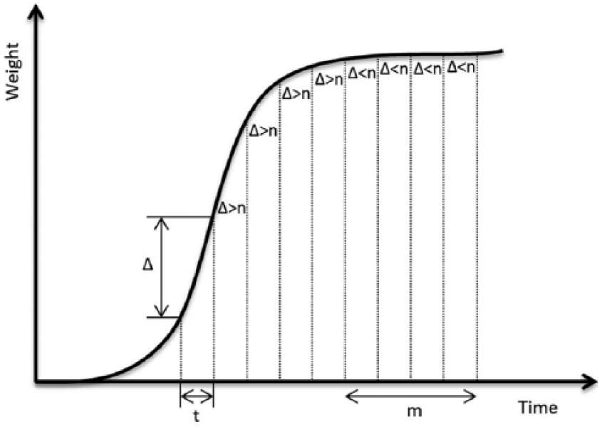
Stability control algorithm
After this method is applied, the stable product weights acquired are shown within a sequence. Here, the number of products whose stable weight can be determined and, based on these values, the performance of the filter can be evaluated easily. In addition, more accurate performance evaluations can be performed by changing the m and n values.
IV. Experimental Results
Weight data obtained using the test set and the software are given in Figure 6 . The measurements performed with six eggs are performed using five different sampling frequencies within the same mechanical system speed. The significance of the sampling frequency in the data collection systems can be easily understood from the graphics in Figure 6 . In addition, as also specified in the datasheet of the integrated ADC, it can be seen in Figure 6 that the root mean square (RMS) noise increases as the sampling frequency is increased.
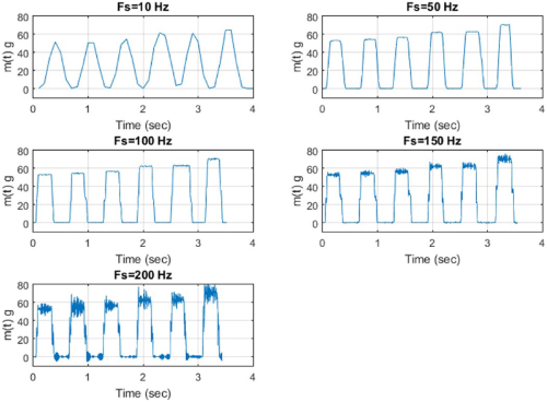
Dynamic weight measurements at different sample frequencies
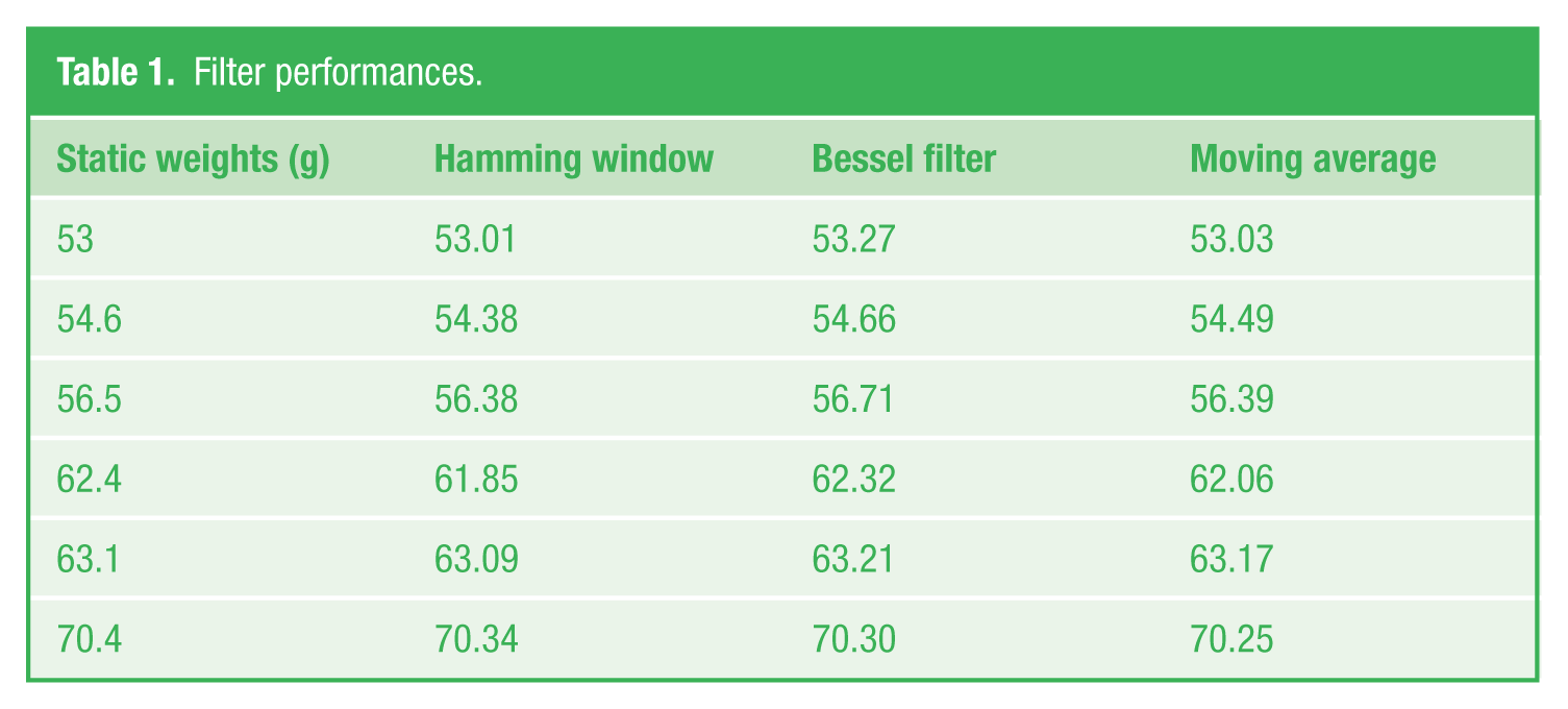
Various filters are applied on the weight data with the 150 Hz sampling frequency obtained and the results are given in Figure 7 . It is possible to change all settings of the filters used and to observe the results in real time. The first filter used is the filter with the hamming window function. Filter degree is selected as 20 and the cutoff frequency is selected as 13 Hz. The second filter used is the Lowpass Bessel filter. Filter degree is 2 and the cutting frequency is 8 Hz. The third filter is the Spencer (15-term) moving average filter. The weights of the eggs are measured and recorded while they are stationary. In order to have a better analysis of the filter performances, the stable weight values obtained as a result of the method applied are given in Table 1 . In this way, as the applied filter settings are changed, the effect of this on the filter performance can be monitored very easily and suitable filters can be designed easily.
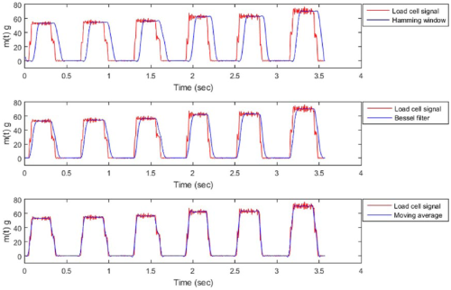
Various filters’ results at 150 Hz sampling frequency
Filter performances.
V. Conclusion
In this study, an electronic and mechanical system where the products can be weighed dynamically is developed. In addition, a computer program is developed for the data collection and filtering applications. All adjustments of the integrated ADC can be performed with the program. It is possible to examine graphically the filtered signal obtained as a result of filtering the obtained weight data with the help of various filters and to examine the performance of the filter by comparing the determined stable weights with the weights measured in stationary status. In addition, as the asynchronous motor controlling the mechanical system is driven with an inverter, it is possible to adjust the speed of the mechanical system as required. In this way, measurements can be obtained in the speeds required and suitable filters can be designed. It is possible to save all results obtained in a text file.
Footnotes
Funding
The author(s) received no financial support for the research, authorship and/or publication of this article.