
Abstract
This paper proposes an accurate and efficient testing system for the safety lock that is used in the suspended access platforms. The measurement methods conform to the standard EN 1808:2015. First, the whole architecture of the system is designed, including the mechanical structure unit, lower control unit, sensors and data acquisition. Second, the upper control software based on LabVIEW is presented. In addition, manual and automatic testing modes are proposed. The field experimental results demonstrated that the proposed testing system has the advantage of high accuracy, high automation and high efficiency.
I. Introduction
In recent decades, suspended access equipment has been widely utilized in various areas, such as constructions, thermal power, chemical industry and wind power. Suspended access equipment carries workers, site personnel and engineers for working at height during the installation of curtain walls and windows, window cleaning, external renovation and decoration of buildings, bridges, chimneys, silos and other structures. The equipment mainly includes a suspension rig, suspended platform, hoist, safety lock, secondary wire rope, suspension wire rope and electrical control system. At present, EN 1808:2015 1 is used as the criteria for the assessment of the safety performance for safety locks. The safety lock, in other words, fall arrest device, is the indispensable part of the suspended access equipment and can catch the secondary wire rope when the platform inclines to prevent the equipment from falling. Generally, the safety lock can be divided into two types, one is the centrifugal-type and the other is the anti-tilting type. According to the international standards EN 1808:2015, safety locks are certified components, which should be tested to comply with the most demanding standards worldwide by third-party testing labs. Before safety lock is taken out of the factory, its safety performance should be pre-assessed by the manufacturer. In China, the government is attaching more importance to the operation safety of suspended access equipment. Legislation dictates that each safety lock should be calibrated at a minimum of every 12 months. Therefore, every safety lock manufacture should have its own safety lock pre-assessing system before inviting the specialized certification agency to do the assessment. The third-party testing lab also requires high-precision and high-efficiency safety lock testing equipment. Currently, the testing system for safety locks lacks high automation and high reliability; at the same time, the intelligence of the system is not high. 2 For the traditional semi-automation testing system, people are required to complete the testing process. It is increasing being of concern and attention of engineers that the automatic degree and measurement precision of the testing system for safety lock.
At present, the automatic and reliable testing systems for safety locks to collect the safety lock performance data are seldom reported in the literatures. The standard EN 1808:2015 presents the schematic diagram of test rig for safety lock. Hence, documentary standards or commonly researches for accurate and automatic measurement system for safety lock are still lacking.
Due to the transient shock of the safety lock, the task that the shock load values are recorded in millisecond time becomes intricate. The drop distance of the platform is also changed in millisecond time, and the traditional displacement measurement method will lead to the damage of the sensor. For example, the cable extension displacement sensor is not adapted in this case. Obviously, a contactless displacement measurement is needed in the testing system.
This paper describes the design and implementation of a highly automatic testing system for safety locks. The system can be applied to test the performances of both centrifugal-type safety lock and anti-tilting type safety lock.
A testing system based on Labview virtual instrument software is built as an organic whole, which consists of mechanical structure unit, low control unit, sensor and data acquisition (DAQ) unit and upper control unit. The system can achieve the function of high measurement accuracy, automatic and reliable operation. In the following, the architecture of the system implementation is illustrated in section II. The measurement methodology is given in section III. Section IV introduces the control method of the test rig. The experimental results are depicted in section V. Finally, the conclusions are summarized in section VI.
II. The Architecture of the Testing System
The testing system should measure three types of data: shock load coefficient, the distance of drop and locking rope angle. The performance requirement of the safety lock is specified in the standard of EN 1808:2015 as follows:
The shock load coefficient shall be ≤5;
The distance of drop shall be <500 mm;
By design, the deck shall remain horizontal within a tolerance of 14° in the longitudinal planes when the platform is rolling on an incline.
In China, the United States, Canada, Australia and New Zealand, the related standards that give the safety rules of the safety lock are GB 19155, ASME 17.1, UL 1322, CSA-Z271, CSA B44.7, AS 1418.8 and AS 1735.9. In these standards, the parameters for the performance of the safety locks are similar to the standard EN 1808. Here, we design a testing system that can obtain the three performance data points, including the shock load coefficient, the distance of drop and the inclined angle.
The system configuration is shown in Figure 1 ; the real system is demonstrated in Figure 2 . The whole system contains four parts: mechanical structure unit, lower control unit, sensor and DAQ unit, and upper computer unit.
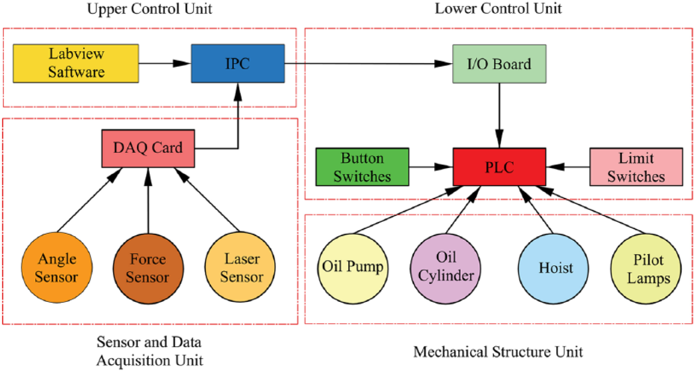
Overall testing system configuration for the safety lock
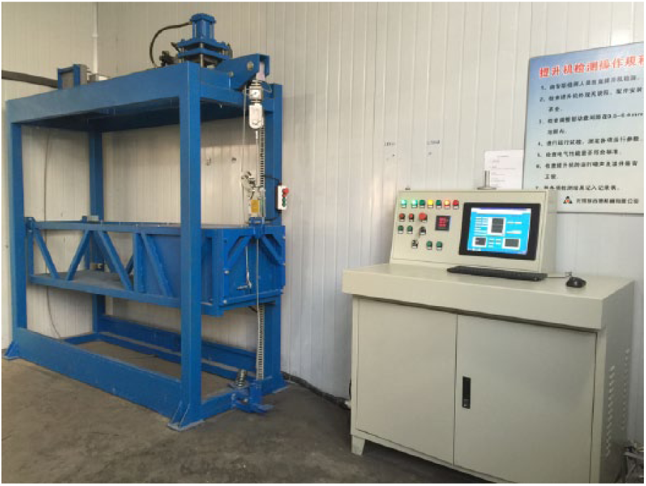
Photograph of the testing system
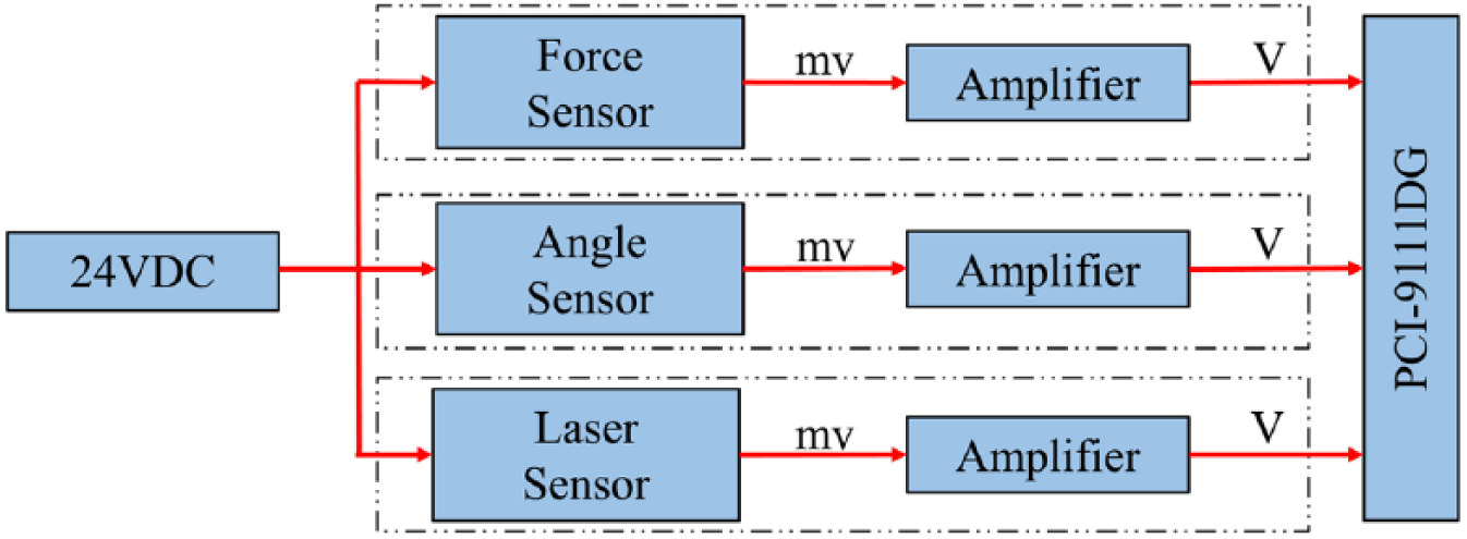
The mechanical structure unit includes an oil pump, oil cylinder, hoist, safety lock and platform and is responsible for simulating the sudden drop of the platform. The safety lock is mounted on the platform. The angle sensor is placed on the surface of the platform. The upper end of the force sensor is suspended by hinges, and the lower end of the force sensor is connected by the secondary wire rope. The lower control unit includes button switches, limit switches, pilot lamps, PLC (programmable logic controller), power supply, and solenoid valve and is designed as the sub-control part of the system. The sensor and DAQ unit includes a DAQ card, force sensor, laser sensor and angle sensor. The DAQ card is installed in the industrial personal computer. The upper computer is composed of the industrial personal computer and the control software programmed by LabVIEW.
III. Measurement Methodology
A. Realization of the test conditions
To simulate the abnormal use condition of the platform, a new type of mechanical structure is designed with size 2600 mm × 964 mm × 2340 mm. The mechanical structure unit is shown in Figure 3 . One end of the platform is rotated freely around the rotating shaft, and the other end of the platform is suspended by the suspension wire rope. The platform is raised or lowered by tightening or extending the suspension wire rope, which is controlled by the hoist.
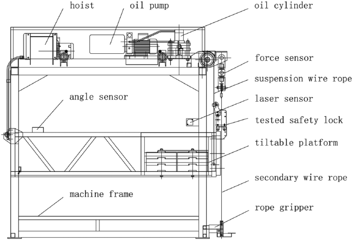
The schematic of the mechanical structure unit
The power of the hoist is 1.5 kW, and the rotation speed is 1400 r/min. A 2.5-kN weight is added to the platform.
When the free-fall testing is performed, the platform keeps in a horizontal position, the oil cylinder moves down and presses the suspension wire rope to prevent its sliding; then the hoist rotates forward to loosen the suspension wire rope, and the oil cylinder moves up at fast speed. Then, one end of the platform falls freely by releasing the load. When the platform accelerates down, the secondary wire rope is caught by the safety lock automatically. The platform comes to a complete stop and a sudden impulse force occurs.
When the angle testing is conducted, the platform stays in a horizontal position, the hoist rotates forward and the suspension wire rope is loosened. Then, the platform descends slowly until the safety lock locks the secondary wire rope.
B. Measurement methods
Shock force
The force measuring apparatus is capable of measuring force from the working load to three times the working load of the hoist with an accuracy of 2% and a frequency bandwidth of 1000 Hz.
The force sensor is a train type sensor, which is made by Ningbo Aien Electronic Co., Ltd, China; the measurement range is 5000 kg. The force sensor can send millivolt level voltage signals to the amplifying converter, and the force signal is represented by a voltage between 0 and 10 V, which can be distinguished by the DAQ card. The force value can be determined as in equation (1)

where F denotes the shock force (kN), and V denotes the output voltage value from the force sensor amplifier (V).
The maximum shock load is difficult to obtain because it occurs in milliseconds and then disappears. If the data sampling frequency is low, the maximum force value cannot be obtained successfully. In the LabVIEW programme, the sampling rate is set at 3000 Hz for the DAQ, which satisfies the minimum sampling rate of 1000 Hz specified in EN 1808:2015.
The shock load coefficient is an important performance parameter of the safety lock and is expressed as in equation (2)
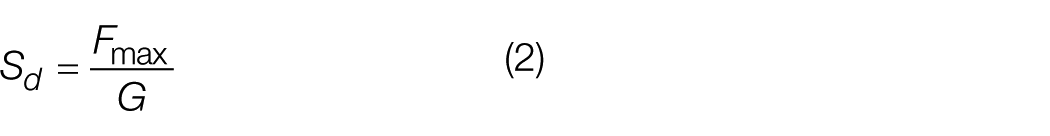
where Fmax is the maximum impulse force value (kN), and G is the initial gravity of the platform weighted by the force sensor (kN). In this system, the initial weight is 2.5 kN.
Distance of drop
The laser displacement sensor is an HL-G112-A-C5, which is manufactured by Panasonic Company, Japan. The laser displacement sensor can measure 0–120 mm distance, and the output voltage is between 1.297 and 10.55 V. The output voltage of the laser sensor is measured under different distances (see Figure 4 ). The relationship between the distance and the output voltage is defined as in equation (3)

where Y denotes the drop distance (mm), and X denotes the output voltage of laser displacement sensor (V).
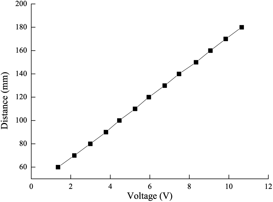
The relationship between the distance and the voltage of the laser sensor
Inclination angle
The angle sensor is a type of MEMS sensor, which can output a voltage signal between 0 and 10 V. The measurement range is between −15° and 15°. The angle sensor is supplied by Shanghai Daoshi Company, China.
The angle value can be determined as in equation (4)

where θ denotes the inclination angle of the platform (degree), and V denotes the output voltage value from the angle amplifier (V). The angle sensor can endure heavy shock during the testing and should be able to endure approximately 200 g shock.
The angle value we need is the stable value, which is changed in the platform inclining condition. For example, in angle testing, the inclined angle of the platform is continuously varied. When the safety lock works, the platform stops falling, and the falling angle is stable. We continuously compare the data and find that the deviation is smaller than 0.1 between adjacent data, and the angle data are recorded.
DAQ
In the testing system, DAQ is extremely important. Data include the following: shock load, angle value and drop distance. The shock load that the secondary wire rope endures when the platform falls must be recorded. The maximum impulse force occurs when the secondary wire rope is locked by the safety lock. It is difficult to grasp the maximum force value because the duration of the maximum force is in milliseconds. If the DAQ card cannot work at high speed, it will fail to obtain the maximum force value. We choose the DAQ card to accomplish the analogue and digital conversion. The DAQ card is a PCI 9111 made by ADLINK company, China. The sampling rate is 110 kHz with 16 channels of AD ports. The resolution is 12 bits. The DAQ card communicates with an industrial personal computer through a PCI bus. From Figure 5 , through the signal amplifier, a millivolt can be enlarged several hundred times and can be accepted by the DAQ card.
The signal processing of the sensor data
IV. The Control Method of Test Rig
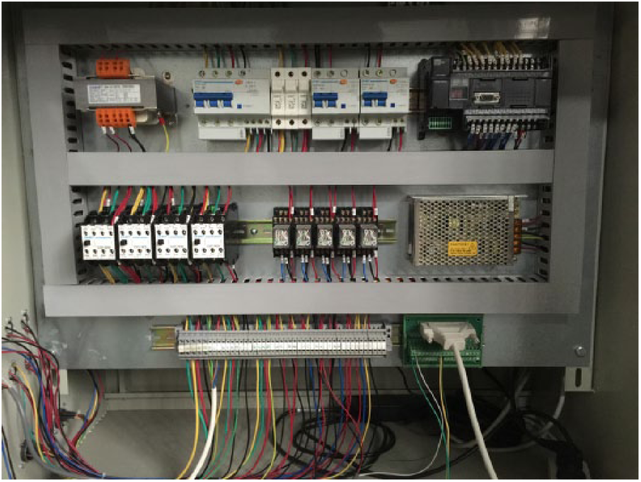
A. Lower control unit
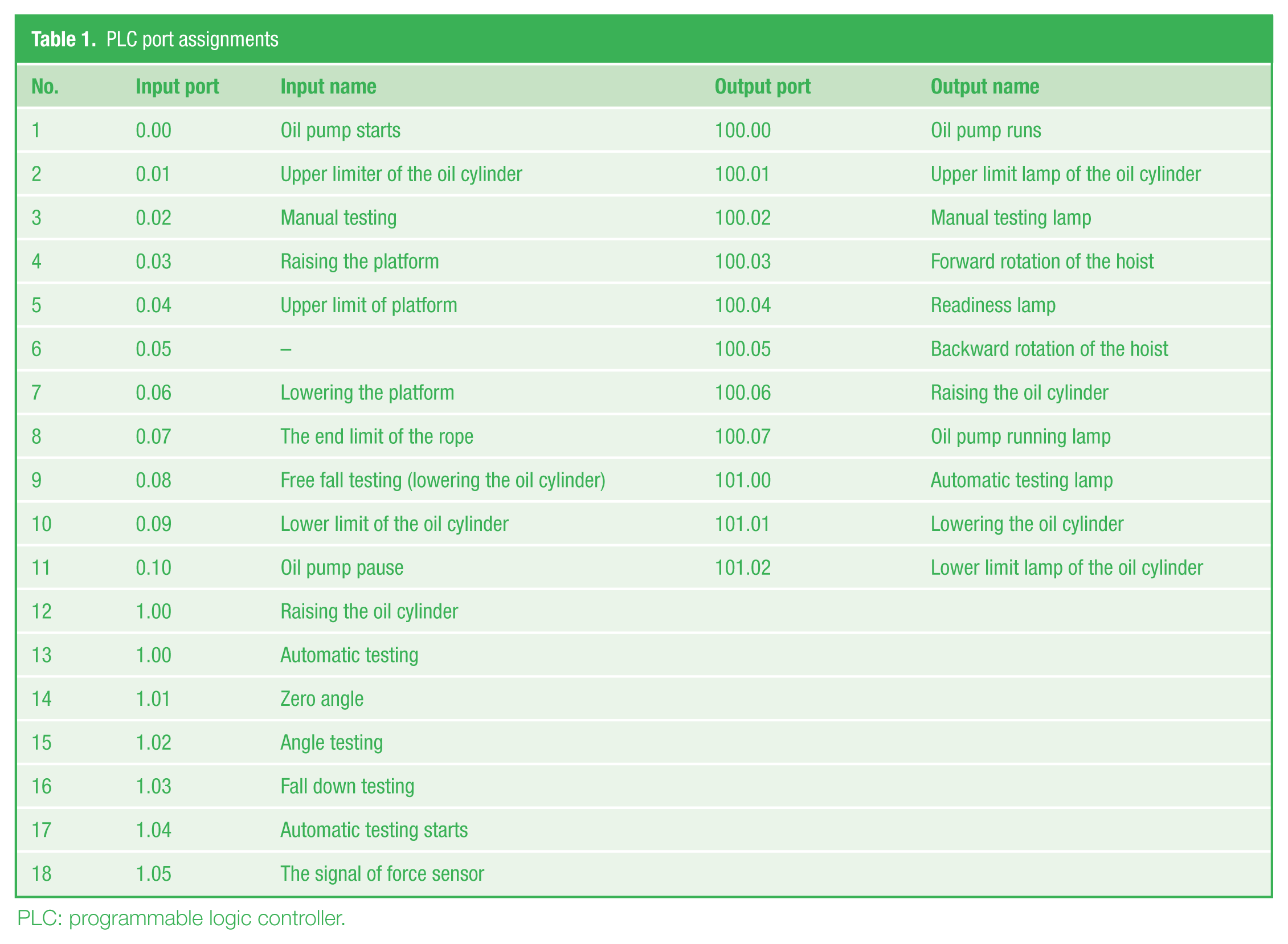
The lower control unit (see Figure 6 .) is in charge of the mechanical action and communicating with the upper computer. The working process is controlled by the PLC. PLCs are widespread in industry and in machines and are well adapted to a range of automation tasks. 3 In this study, we used the CP1H-X40DR-A OMRON PLC as the core controller. This type of PLC has 40 digital ports, 24 input ports and 16 outputs. The power supply is 100–240 VAC. The rated input voltage of the digital input is 24 VDC, whereas the maximum voltage of the digital output is 250 VAC (maximum current is 2 A) or 24 VDC (2 A). The PLC programme was written in CX-Programmer Version 9.5. In the PLC control program, 17 input ports and 11 output ports are used, and the definition of the ports is given in Table 1 . The oil pump, oil cylinder, hoist, pilot lamps, button switches and limit switches are controlled by the PLC.
Lower control unit
PLC port assignments
PLC: programmable logic controller.
The button switches and limit switches send instructions to the PLC, and the oil pump, oil cylinder, hoist and pilot lamps execute instructions according to the PLC control program.
B. Manual testing
The testing system can be operated in manual testing mode when the operator does not need the automatic testing mode. The manual testing procedures are expressed by Petri nets. The PLC programme can be written easily according to the Petri net diagram. The hoist should be mutually locked between forward and backward rotation. The angle testing for the safety lock is performed as follows:
Step 1. The system is powered on.
Step 2. Switch to manual testing mode.
Step 3. Mount the safety lock on the platform.
Step 4. Hoist moves forward, and the platform rises.
Step 5. The platform reaches the horizontal condition.
Step 6. Hoist runs backward, and the platform descends slowly.
Step 7. Safety lock works.
Step 8. Obtain the signal of the angle sensor.
Step 9. Return to Step 4 until the specified testing times are reached.
The free-fall testing for the safety lock is performed as follows:
Step 1. The system is powered on.
Step 2. Switch to manual testing mode.
Step 3. Mount the safety lock on the platform.
Step 4. Hoist runs forward, and the platform rises.
Step 5. The platform reaches the horizontal condition.
Step 6. The oil cylinder moves down and presses the suspension wire rope tightly.
Step 7. Delay 1.5 s.
Step 8. The oil cylinder moves up and the platform falls freely.
Step 9. Obtain the signals of the force sensor and laser sensor.
Step 10. The shock load and drop distance are recorded.
Step 11. Return to Step 4 until the specified testing times are reached.
C. Automatic testing
Automatic mode automatically performs all of the testing processes. In automatic mode, some of the button switches are disabled to prevent operation error.
The testing cycles of the angle testing and free-fall testing can be set in LabVIEW software, for example, three times. When angle testing is performed, the inclined angle can be recorded when the safety lock catches the secondary wire rope. When free-fall testing is conducted, the distance of the drop and shock load is recorded when the safety lock works. The PLC programme automatically runs the angle testing three times and then the free-fall testing three times. Each time, the testing data are recorded in the testing report in WORD format. After completing three tests, the average testing values for the inclined angle, distance of the drop and shock load are calculated and recorded on the testing form. The PLC and LabVIEW programmes are introduced as follows:
Step 1. The system is powered on.
Step 2. Switch to automatic testing mode.
Step 3. Mount the safety lock on the platform.
Step 4. Hoist runs forward, and the platform rises.
Step 5. The platform reaches the horizontal condition.
Step 6. Click the ‘Automatic testing’ button on the LabVIEW software.
Step 7. Hoist runs backward, and the platform descends.
Step 8. The safety lock works.
Step 9. When the value of the force sensor reaches 2.5 kN, acquire the angle value of the angle sensor automatically, and after 0.5 s, the hoist stops. After 10 s, the hoist runs forward until the platform is horizontal.
If free-fall testing is needed, the free-fall testing can be performed automatically after step 9, as follows:
Step 10. The oil pump is powered.
Step 11. The oil cylinder moves down and presses the suspension wire rope.
Step 12. The hoist run backward for 1.5 s and loosens a sufficient length of suspension wire rope.
Step 13. The oil cylinder moves up, and the platform falls freely.
Step 14. The maximum shock load is recorded.
Step 15. The drop distance is recorded.
Step 16. The hoist runs forward, and the platform rises.
Step 17. When the inclined angle is equal to zero, the hoist stops.
For the centrifugal-type safety lock, free-fall testing can be performed automatically three times. For the anti-tilting-type safety lock, the angle testing and free-fall testing can be conducted three times. The angle testing and free-fall testing can be solely performed automatically three times in automatic mode.
D. Communication between the PLC and upper computer
The PLC can communicate with the upper computer though the OPC server in LabVIEW, and the communication configuration process is complicated. In the real time control fields, the reaction speed of the OPC technology is relatively slow. The PCI-9111DG DAQ card has 16 TTL output digital channels. In this study, five digital output channels of the PCI-9111DG DAQ card (DO0, DO2, DO4, DO6 and DO8) were used as communication channels with the PLC. The output voltage of the DO pins was 0 VDC at the low level and +5 VDC at the high level. A TTL voltage converter was applied, and the +5 VDC signal can be amplified to +24 VDC. Through the function of the voltage converter, the amplified signals can be connected to the input port of the PLC. Thus, the upper computer can send control commands to the PLC, and the PLC can execute the corresponding program. The corresponding communication ports of the PLC and DAQ are shown in Figures 7 and 8 . The definitions of the I/O ports are shown in Table 2 .
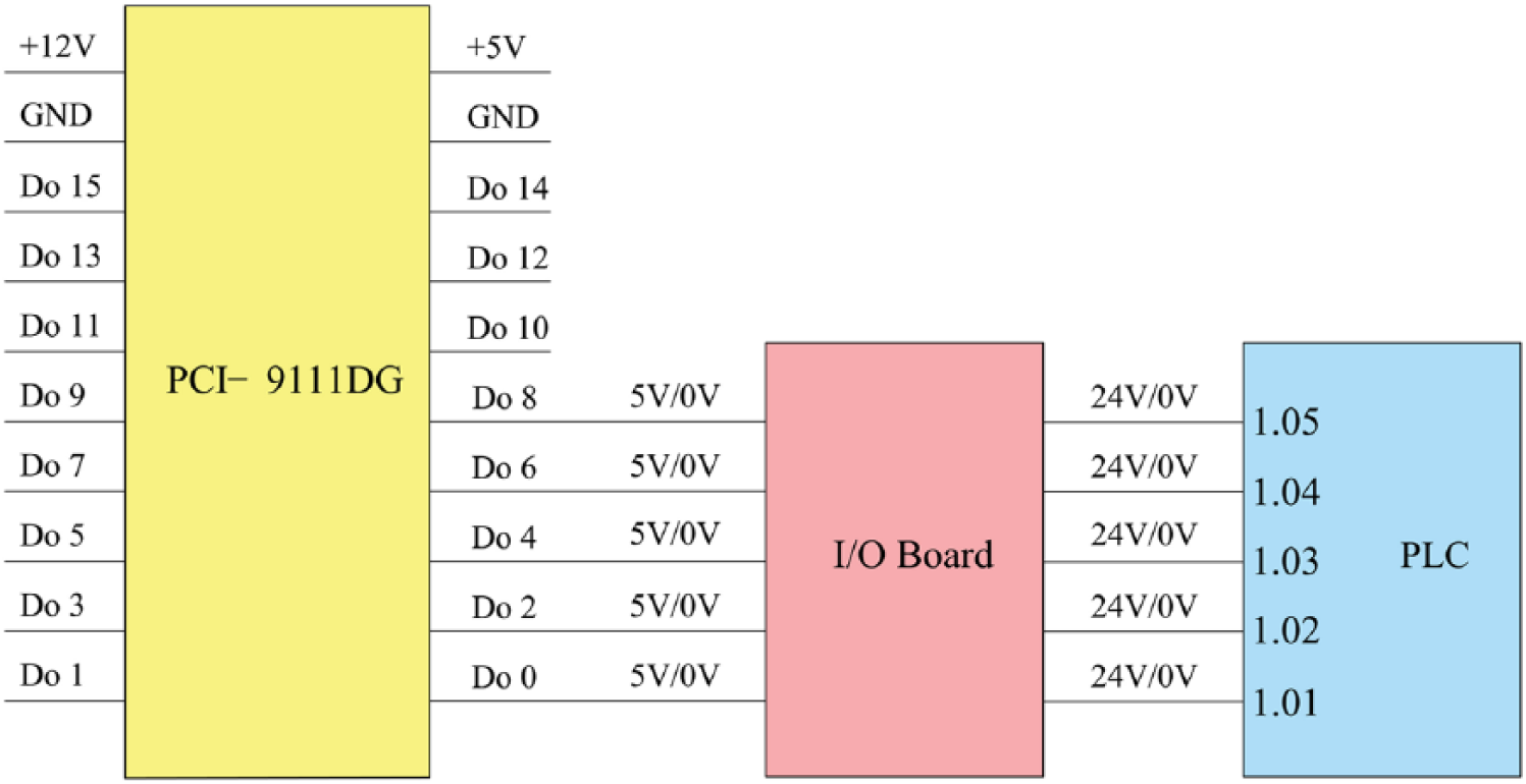
The communication between the data acquisition card and the PLC
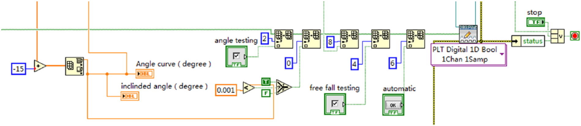
LabVIEW module for I/O communication
Definition of the I/O ports
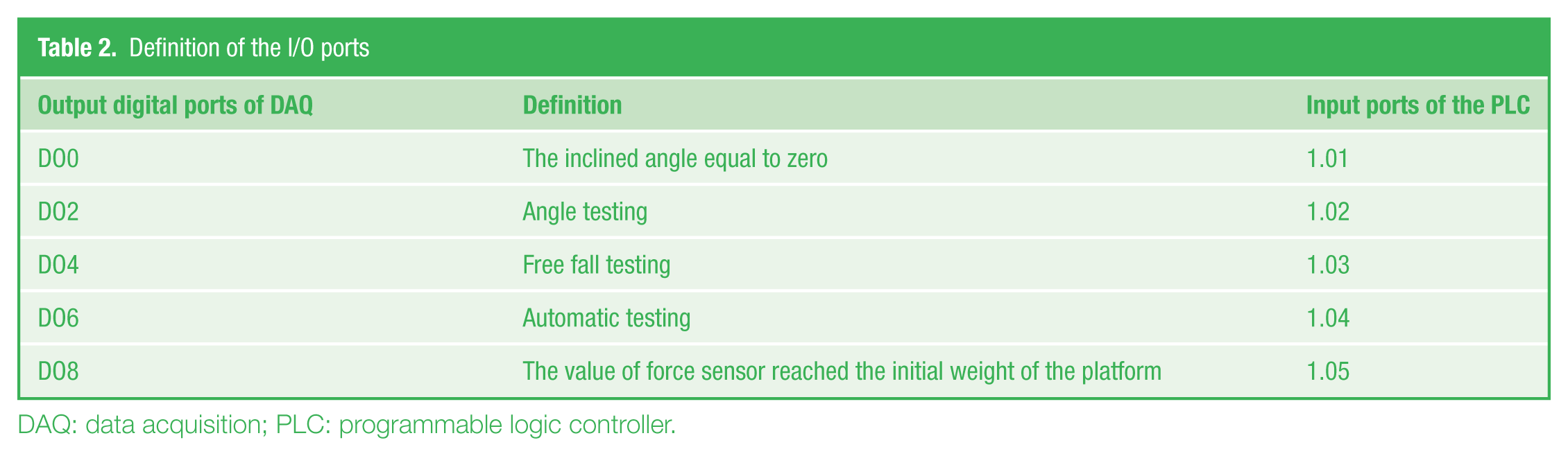
DAQ: data acquisition; PLC: programmable logic controller.
E. Labview software
LabVIEW, by National Instrument, is widely used as a measurement software development tool in both academic and industrial research and development. LabVIEW is an industry-standard graphical programming environment that can be used to quickly and easily acquire, analyse and present data from a DAQ card.4–7 In this study, LabVIEW programs were built in the LabVIEW 2014 software environment. The validity of these proposals has been evaluated experimentally in a real system. The LabVIEW software interface is shown in Figure 9 . Two types of safety locks were tested in the field experiment at Wuxi Rigid Machinery Limited Company. After testing, the testing report was generated by the software. The testing report is reconfigurable under the requirements of different users.
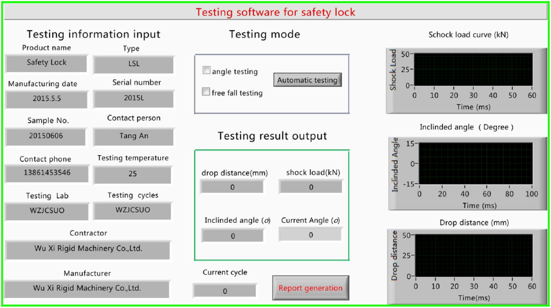
LabVIEW software graphic interface
In the angle testing, the inclined angle must be recorded, and the impulse force should be omitted. In impulse force testing, the maximum impulse force should be recorded, and the drop distance is measured by laser displacement sensor, while the inclined angle should not be recorded in the testing report.
The data filtration mechanism is setup in the LabVIEW programme. We create the data filtration method by determining the value of the maximum impulse force. If the maximum impulse force is larger than 1.5 times the initial gravity of the platform weighted by the force sensor, we regard the test a free-fall testing. If the maximum impulse force is smaller than 1.5 times the initial gravity of the platform weighted by the force sensor, we regard the test as angle testing.
A testing report is generated automatically by LabVIEW; the Report Generation Toolkit in the LabVIEW 2014 is convenient to create the testing report using the WORD template. The testing parameters and the testing results can be recorded on the test report. Once the test process is completed, the testing report is also created. For different users, the WORD template of the testing report can be re-organized. The block diagram of the report generation is shown in Figure 10 .
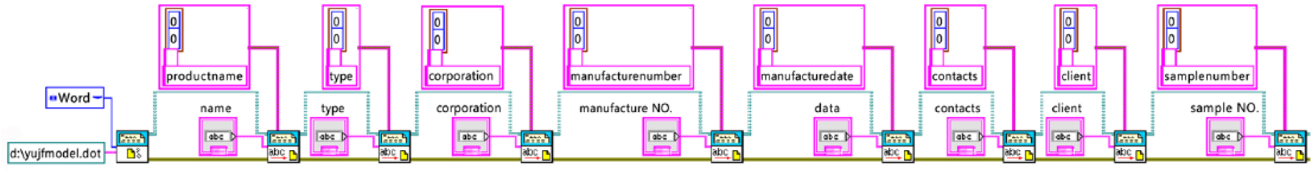
Report generation module
V. Experimental Results
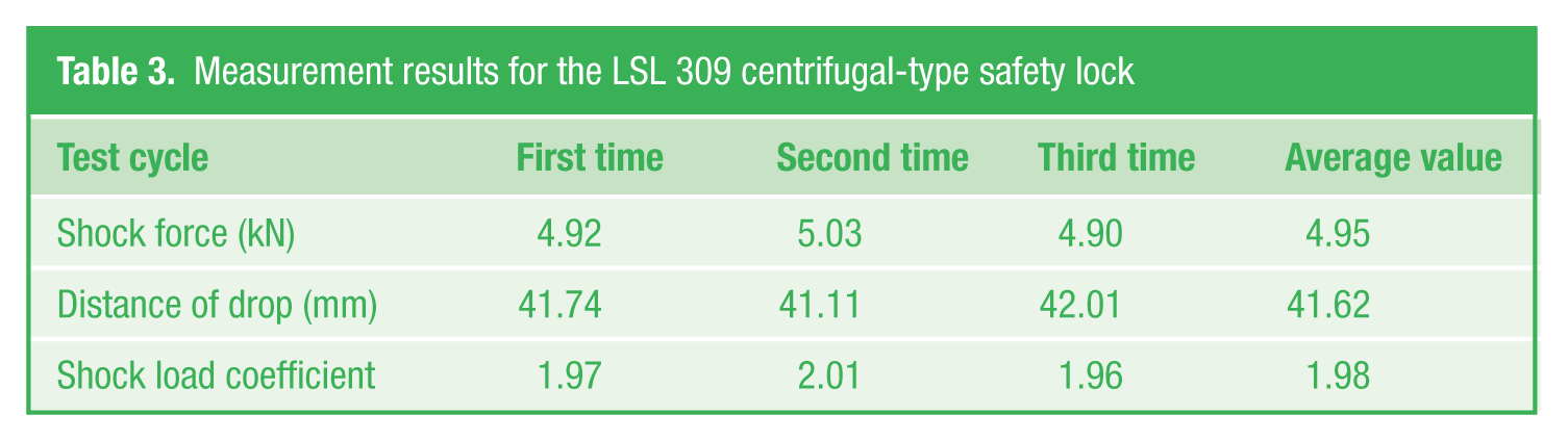
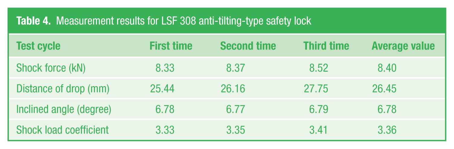
For the centrifugal-type safety lock ( Figure 11 ), only the free-fall test was conducted, and the shock force and the drop distance were recorded. Table 3 gives the measurement results for an LSL 309 centrifugal-type safety lock. Table 3 shows that this safety lock is qualified according to EN 1808:2015. Figure 12 shows that the shock load is 4.95 kN in the first test, and the shock load coefficient is 1.98, which is <5. For the anti-tilting-type safety lock ( Figure 13 ), the angle test and free-fall test were conducted. Table 4 gives the measurement results for an LSF 308 anti-tilting-type safety lock. Table 4 shows that this safety lock is qualified according to EN 1808:2015. Figure 14 shows that the shock load is 8.40 kN in the first test, and the shock load coefficient is 3.36, which is <5. Figure 15 shows the inclined angle curve for the LSF 308 centrifugal-type safety lock. From the testing results, it was concluded that the two tested safety locks were qualified according to standard EN 1808:2015.
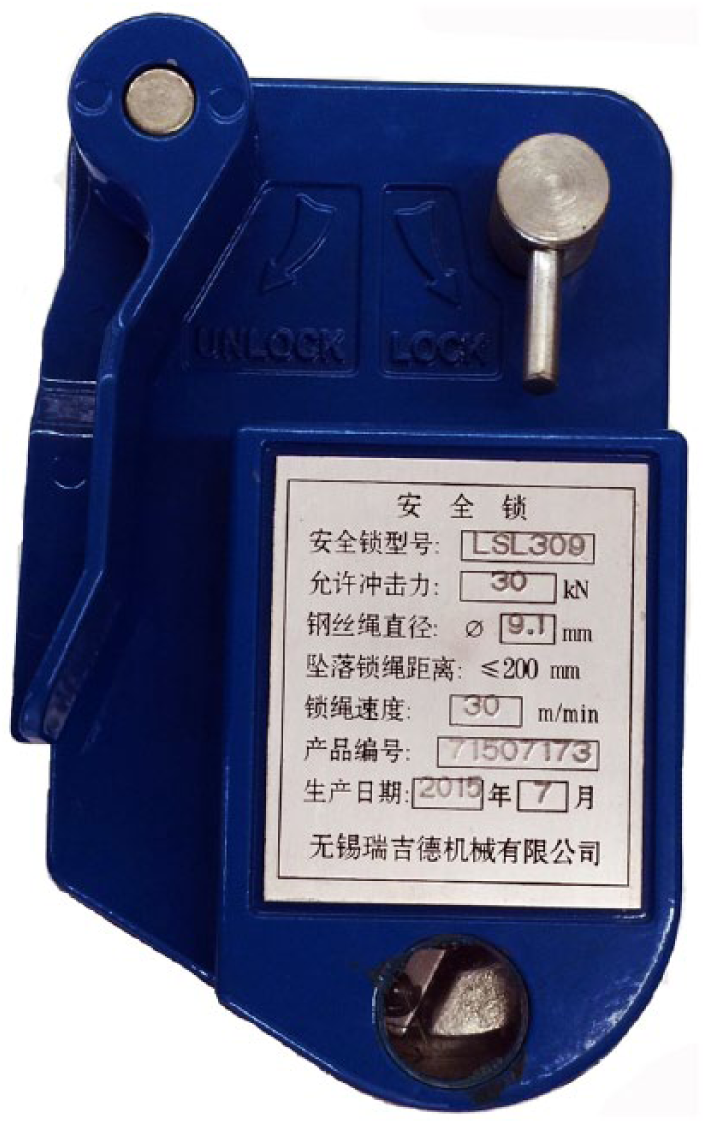
Centrifugal-type safety lock
Measurement results for the LSL 309 centrifugal-type safety lock
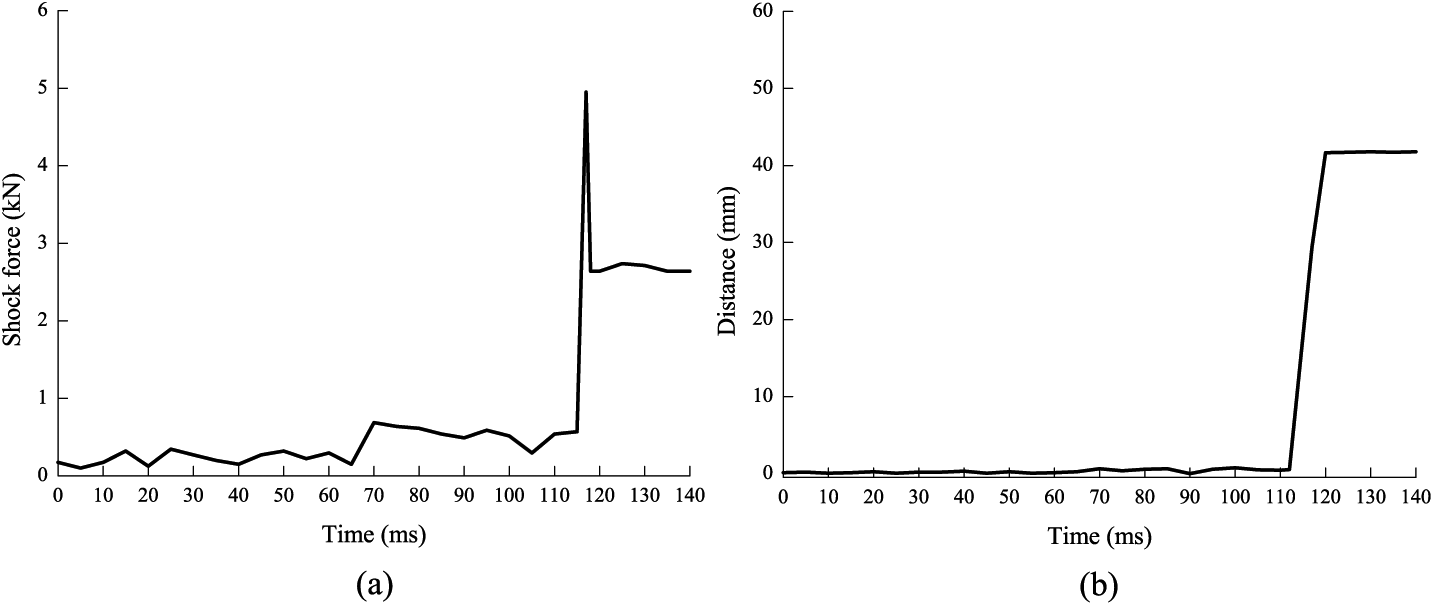
Shock load and distance curves for the LSL 309 centrifugal-type safety lock
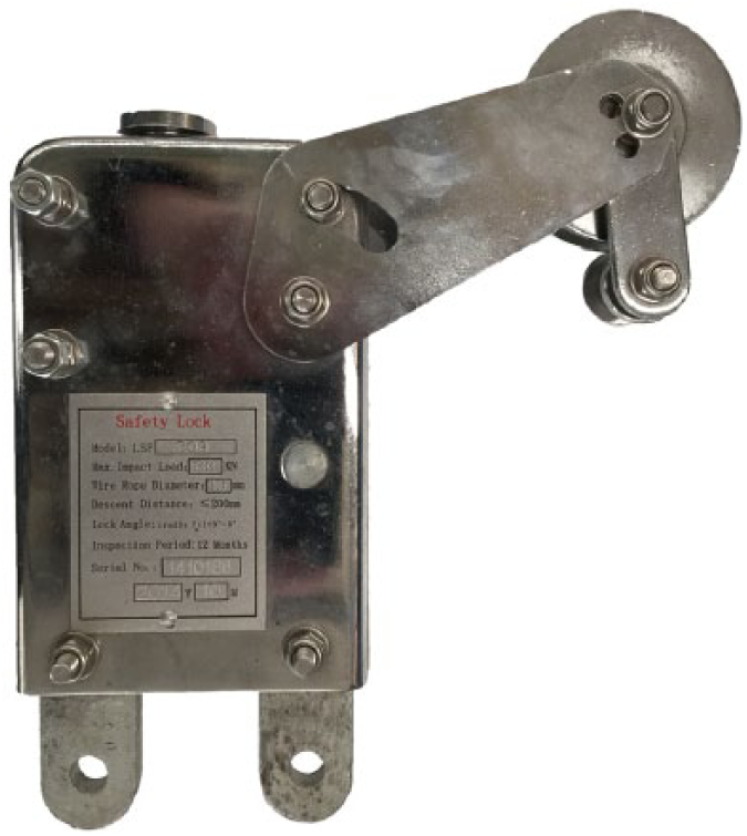
Anti-tilting-type safety lock
Measurement results for LSF 308 anti-tilting-type safety lock
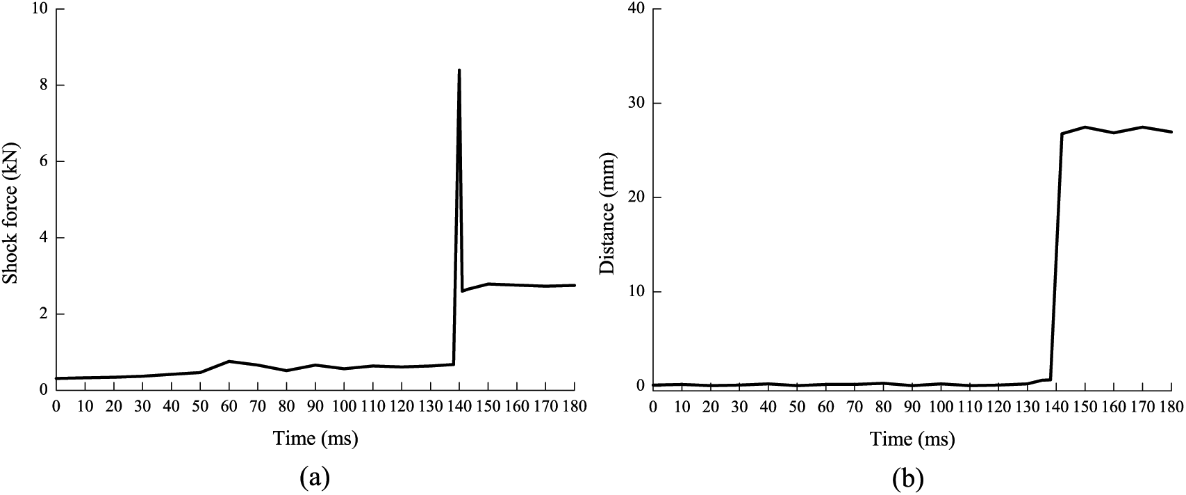
Shock load and distance curves for the LSF 308 anti-tilting-type safety lock
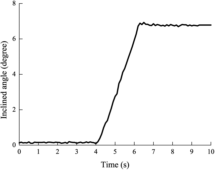
Inclined angle curve for LSF 308 anti-tilting-type safety lock
VI. Conclusion
An automatic testing system that is specifically used for safety locks is proposed based on the specifications given in EN 1808:2015 using the LabVIEW virtual instrument software architecture. The testing device for the safety lock was carefully developed and applied to the safety lock manufacturing company and a third-party testing lab. Performance items of the safety lock can be recorded in the testing report. The testing processing can be divided into manual mode and automatic mode. Manual mode is suited to the debugging of the testing system, whereas the automatic mode is useful for improving the testing efficiency. The technical parameters of the system are as follows:
Inclined angle of the platform: 0–15°;
Permitted maximum shock force: 50 kN;
Diameter of the suspension wire rope: 8.3–10.2 mm;
Drop distance: 0–300 mm;
Standard weigh: 2.5 kN;
Supply power: 380 V/50 Hz;
Total power: 4.5 kW;
Total weight: 1200 kg.
The advantages of the testing system are as follows:
The system adopts a high-speed DAQ card, LabVIEW software technology and high-precision sensors. The measurement accuracy is guaranteed. The shock load value can be successfully obtained in milliseconds. With the help of the LabVIEW software and PLC program, the system has the advantage of high efficiency, high automation and high accuracy.
The testing system is designed in accord with EN 1808:2015, and the testing system has been put into practice in factories and third-party labs. The field experiments show that the testing system is effective to measure the performances of the safety lock.
Footnotes
Acknowledgements
The authors would like to acknowledge Mr Li Qing for his technical assistance in improving this work.
Funding
This work was supported by Jiangsu Natural Science Foundation (under Grant BK20141114), Jiangsu Industry-University-Research Strategy Fund (under Grant BY2015019-28) and the Wuxi Small-medium Enterprise Innovation Fund (under Grant WX0301-B010508-150059-PB). This work is also partially supported by Wuxi Rigid Machinery Limited Company.