
Abstract
The work presents the possibilities of applying modern measuring techniques, classic and coordinate measuring techniques in the forging industry (various stages of technological sequence), with the use of various measuring tools, instruments and machines applied in workshop metrology. The work points to different aspects of measuring techniques used mainly for two groups of objects, emphasizing their important role in the context of safety (achieved forgings—products) and the significant measurement problems due to the extreme conditions in industrial hot forging processes. The first group comprises various measurements of forgings (control during and after forging and mechanical treatment). The second group includes measurements of the forging equipment involving a broadly understood quality control (geometrical characteristics, surface quality etc.), often combined with comprehensive control and durability analysis of forging tools. The work analyzes the possibility and validity of applying scanning techniques for direct control of the quality and change of the geometry of the tools in industrial forging processes, without the necessity of their disassembly, and also measurement systems of temperature, forces and displacement in forging processes.
I. Introduction
The basis for the development of industry is a continuous perfection of the product, improvement of its quality and reduction in the production costs, which are indirectly connected to the reduction in the measuring time by very complicated measuring procedures. This process is possible due to continuous improvement of the measuring techniques and the introduction of new computer-aided design and computer-aided manufacturing (CAD/CAM) methods. At present, the classic measuring techniques and the coordinate measuring technique (CMT) provide the best possibilities of development for the modern metrological thought, also in the field of the forging industry.1–6
The high competition on the forging market is the reason why, besides the price, the quality of the offered forgings, forming the main criterion for the selection of the supplier, is a parameter which more and more often determines the selection of the vendor. This is especially crucial in the case when the recipient of the product is the automotive and the aircraft industry. The processes of die forging are one of the most difficult ones with respect to implementation. Despite the fact that this technology is relatively well known, producing a proper forging of a complicated shape, which will meet the requirements of the recipient regarding the precision and quality, requires high experience on the part of the technologists and operators. In each stage of the forging process, there is a potential risk of error, which lowers the quality of the produced forgings. One of the basic factors affecting the quality of the forgings is the tools (their quality and precision) as well as the machines and devices (operational state, clearance etc.) used in the forging processes. The wear of the forging tools as well as the remaining instrumentation (casings, shim rings, sleeves, washers, wedges etc.) causes a change in the geometry of the product, and any surface flaws of the tools (cracks, defects) are reflected in the forged product,7,8 affecting its quality. This is also the case of forging aggregates and other supplementary devices. Presses and rams working under hard conditions characteristic of the forging process are often over-used, which causes a much faster wear of their elements and subassemblies. This, in turn, is reflected in changes in the geometry of the body, shape lapses and location of the table tops as well as slide guides. That is why, during the production process, it is so important not only to control the quality of the forging but also that of the forging instrumentation, as well as to periodically control the key elements of the forging machines and devices. In the majority of the industrial plants working in the field of forging production, such check-ups consist of a visual assessment of the quality of the produced element or of the particular tools (dies, stamps, pushers etc.) as well as in performing a measurement in selected control points with the use of traditional measuring devices or simple curve gauges. The least frequent control is performed on the forging aggregates, and that, often, only in the case of failure. The currently used classic measuring methods do not allow for a fast and complex assessment of the quality and precision of the whole object. Such analyses are possible owing to the application of CMT with the use of coordinate measuring machines and scanners, or measuring arms with integrated scanners, which allow for a measurement directly during the production process.1,3,9
Most of the forging plants in Europe still use the classic measuring tools for the quality control of forgings, forging equipment, machines and devices. They include universal tools for measuring the length and diameter (of digital and analog slide calipers, analog micrometers, two- and three-point rod gauges, gauge blocks, feeler gauges, height gauges, protractors, cogged detectors, detector instruments etc.). This is mainly the result of two issues. First, for many years, this type of instruments has proved to be effective in the forging industry. Also, they are reliable, simple and provide results in a short time. Second, industrial plants, despite having the awareness of the necessity of quality control, do not give enough weight to the instruments and methods of measurement due to financial reasons. They often use the principle of simply measuring or checking the given size or shape because such has been the practice for many years. At present, more and more frequently, especially at modern forging plants, it is not the case, as more weight is given to applying better and more precise measuring tools as well as other measuring methods. This is also directly connected with the increasing demands of the recipients of the forgings.6,10–12
The CMT provides a lot of possibilities for the development of modern metrological thought. In industrial coordinate metrology, new trends are being observed. The most apparent change is the necessity to apply three-dimensional (3D) numerical models for the determination of the nominal values during the measurement. This is connected with the modern dimensional approach International Organization for Standardization Geometrical Product Specifications (ISO GPS), which requires integration of the measuring software for the measuring machines with the CAD numerical models.3,5,13–15 Another important trend is increasing the number of measurement points necessary for determining the analyzed geometrical properties. 16 One of those properties is the volumetric wear parameter, which can also be used in the analysis of the shape changes of forging tools, with the purpose to prognosticate their wear process. Among others, this parameter is used in medicine. For example, in previous works,17,18 the authors present the use of a coordinate measuring machine equipped with a contact measuring head for analyzing the volumetric wear parameters of the spherical surfaces of joint prostheses. Langton et al. 19 expand the research concerning the analysis of the effect of the change of numerous scanning parameters, with the use of the contact scanning measuring head, whereas the authors of other works20–22 analyze the “beneficial” effect of increasing the number of measurement points on the accuracy of the determined volumetric parameters.
Additionally, the industry is more and more interested in mobile measuring devices. These undoubtedly include measuring arms equipped with linear laser scanners with dedicated specialized software, which, through their mobility and universality, are an alternative for the coordinate measuring machines in applications requiring lower accuracy.23,24 This interest stimulates an analysis of such type of devices with respect to their applications in the forging industry, among others, for the analysis of the geometry change in the tools during the forging process as well as a periodical assessment and control of the forging aggregates or to build special measurement and control systems.2,10,12,25–27 Up till now, the available literature provides only information on the application of 3D scanning techniques for the analysis of the geometry changes in the product but not the assessment of the state of the tools and machines which produce it. The 3D scanning technique, also with the use of measuring arms, is mainly applied in the product end quality control.23,28,29 These measurements are most often based on the assessment of the shape errors of the determined contour and surface. The available literature more and more frequently discusses applications of this kind of methods for the measurement, control and evaluation of the state of swaging tools. An example of such application of the 3D scanning method 30 is the use of an optical scanner for the determination of the shape errors of a given surface and next, on the basis of the obtained data, providing the geometrical specification for the process of rebuilding. Another application of the 3D scanning method with the use of scanners9,31 is the use of the analysis of the shape errors of a given surface for the evaluation of the wear of the forging tools—nitrided or coated with hybrid layers.
It is worth noting that all the measuring instruments used in the process of quality control are periodically checked up, which allows for a correlation with the superior patterns. The fulfillment of this basic process requirement allows for the production of components by many sub-suppliers in the global system of interchangeability of parts.
II. Forging Measurement and Quality Control
The technological process of die forging consists of several stages, which include delivering the material from the plant, its cutting and heating, as well as a thermal treatment of the final product ( Figure 1 ). At each of the mentioned stages, there is a potential risk of an error causing a forging flaw.
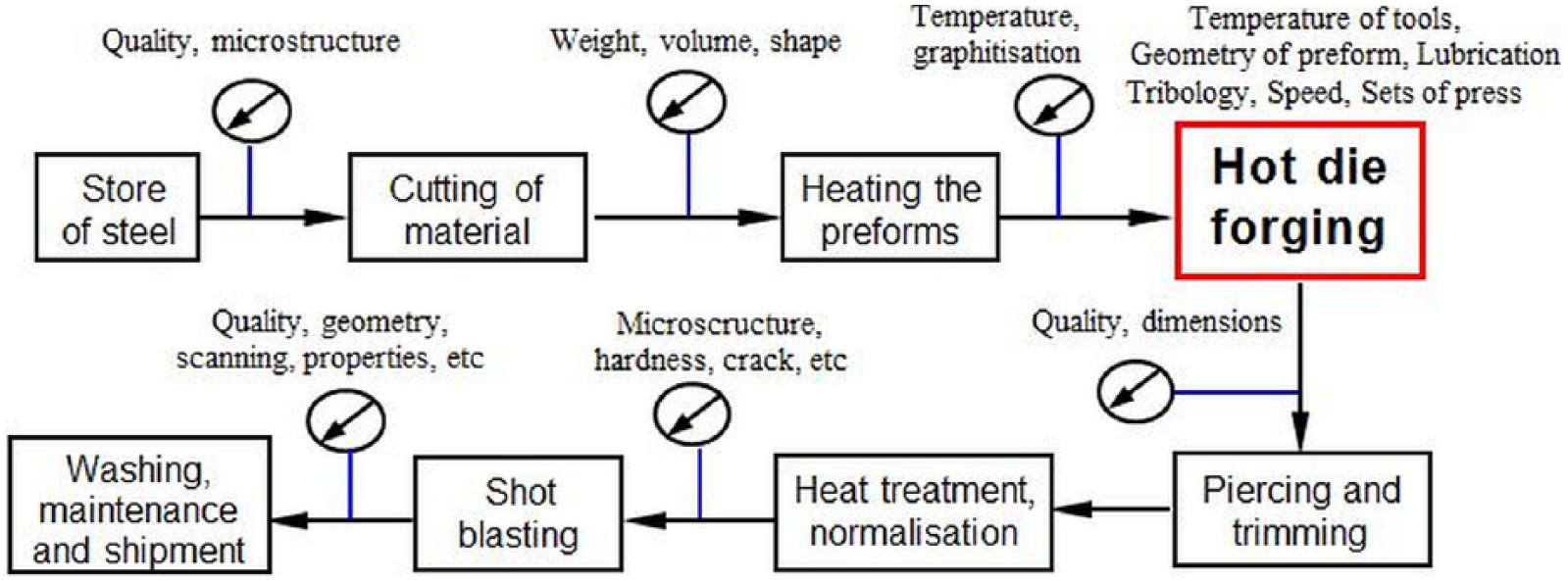
Flowchart of hot die forging technology 8
Another factor affecting the forging quality is the durability of the tool, as its too fast and intense wear causes change in the geometry of the manufactured product, and any surface defects (fractures, decrements) are reflected in the forged product. Among the most important factors influencing the course of the forging process are the precision of the input material cutting, the manner of lubrication and the factors related to the tool and forging machines.8,32,33
The control of the forgings often depends directly on the recipient. It is the client who decides which dimensions are important and are supposed to be verified and whether such control should be carried out statistically or to 100%. The client pays and thus decides about the type of the inspection, which can be a macroscopic, visual or flaw detection analysis or all of them. The standard control of the forging processes includes the following: the charge material, the preform and the forgings after the particular operations, as well as the forging after the mechanical treatment, that is, the ready product.
In the case of the measurement of the charge material, the control usually concerns its mass and geometry after cutting. There are two possible ways of rod cutting into appropriate dimensions of the charge material. The most frequently used one is cold or hot cutting with breaker knives (in the case of large diameters). A less frequently applied way is cutting with a saw, which, on one hand, is more precise and does not cause burrs or geometry changes, and on the other hand, it is less efficient (it lasts longer) and involves material losses in the form of chips. That is why the control of the charge material more often concerns the preform cuts with break knives.34–38
The authors investigated for cracks in the forging casing of constant velocity joint body (CVJB), which was the probable cause rupture of input material created during cutting.33,39 Figure 2 presents an example of preform fracture during cold cutting from steel bars. The preforms are characterized by an uneven surface, and there is a visible fault around the edge of the cut bar. The microstructural tests of the specimen revealed a significant decarbonization of the layer at the external surface. The ratios of the ferrite and pearlite percentage in this area equaled from 60% to 40%. This defect is especially risky, as it eliminates the produced preforms from further forging procedures. The cut input material does not usually undergo a quality control, which would make it possible to eliminate the defected specimen. Such fracturing can be spotted on the forging only after it has been cleaned of the scale and graphite layer, and, in the worst case, it can be a hidden defect ( Figure 2(c) ).
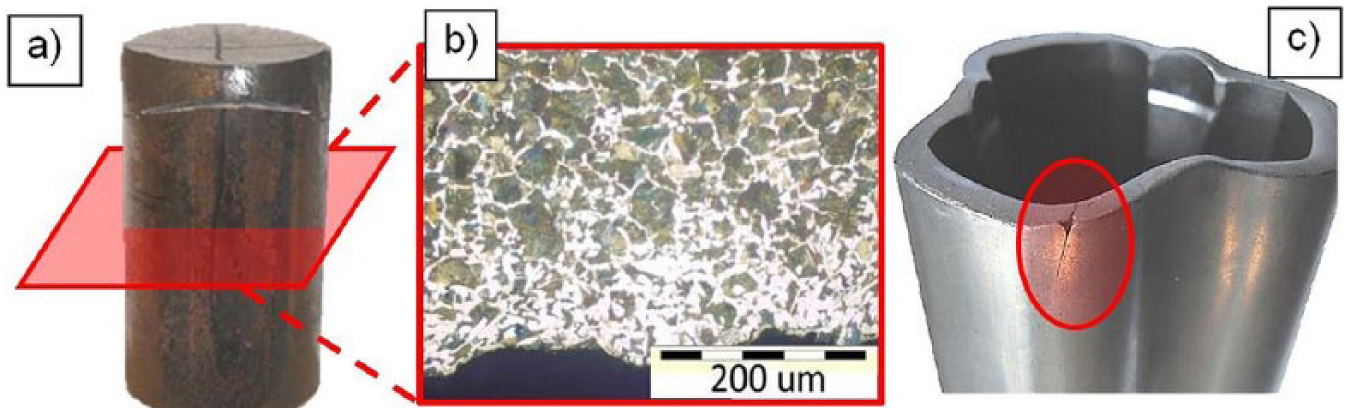
A view of (a) fractured preforms, (b) XC45 steel structure, surface layer and (c) a forging from a fractured perform 39
The authors performed numerical modeling of the cutting process of the preform bar with the use of the Forge program (commercial finite element method (FEM) software based on Finite Elements Method), in order to more thoroughly analyze, as well as solve, the problem of fracturing. A schematic representation of the cutting system is presented in Figure 3 . The basic parameter, which undergoes regulation in the cutting process with the use of shears, is the size of the gap between the upper and lower blades, which affects the quality of the cut preform.
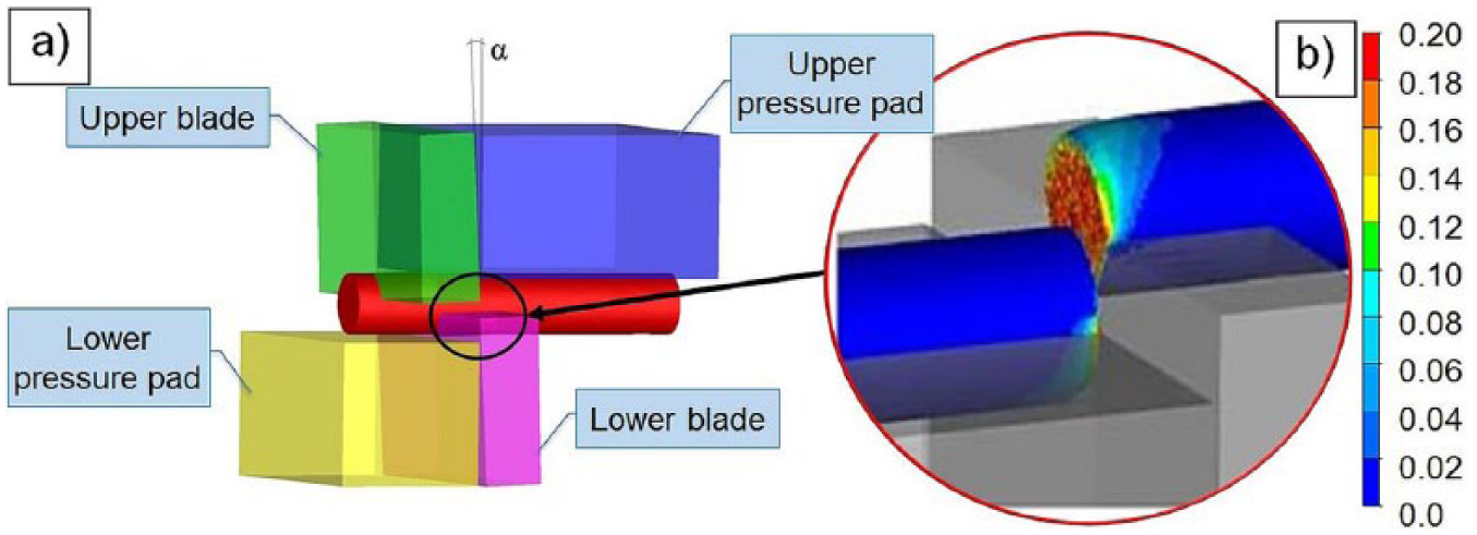
Schematic representation of the cutting method: (a) numerical model of the cutting process after changes—introduced blade inclination and (b) results of FEM using the Cockroft–Latham fracture criterion 33
In order to select the appropriate parameters of the cutting system (value of the gap and the system inclination), a series of numerical FEM simulations of the cutting process was performed. The fracture model according to the Cockroft–Latham criterion was applied. Exemplary results are presented in Figure 3(b) . The problem of fractures was solved by way of correcting the geometry of the blade’s edge so that it would be parallel to the axis of the cut bar and not cause a bending stress in the bar.
In the majority of forging plants, geometry controls are sporadically performed, and they mainly focus on the mass of the charge material (with the use of scales), significant in the die forging process, as it affects the appropriate filling of the impression. An example is a 100% quality control of the billet weight, which uses the automatic measurement system on the line, where each billet is weighed, and the scales’ reading determines whether it is used in the further process or is rejected. 8
On automatized forging lines, the cut material is placed in an automatic feeder/dispenser, which delivers it to the induction heater. Before the heating, the material undergoes quality control through a specially designed system, in which preforms with flaws, such as cracks or burrs, are removed from the process. The system applies a module for measuring the geometrical shape of the charge with the use of the laser technique, a visual module for the optical inspection of the charge’s surface and scales for the dynamic measurements of the charge’s mass and a pyrometer to determine the correct temperature heat preform.
During the initiation of the forging process, forgings from the particular operations are sampled with the purpose to check the machine’s settings and the appropriateness of the assembly and production of the tools themselves. Directly in the production are controlled: the appropriate heat temperature of input material and the hot forging undergoes check-up, and its key geometrical characteristics are evaluated ( Figure 4 ). Measuring the temperature of input material is carried out by a pyrometer, often connected to the sorter of improperly heated preforms ( Figure 4(a) ), and hot forging is done mostly with the use of calipers ( Figure 4(b) ) or caliper altimeters ( Figure 4(c) ). Temperature measurements of input material and forgings are important for the correctness of the process and assumed properties. Often, they pose quite a challenge and a major problem because they are difficult to execute. It is noteworthy that in the case of the classic measurement of hot forgings using measuring equipment, measurements are carried out at an ambient temperature, and nominal dimensions of the product are converted to the picture of hot forging. This is an exception to the requirements of the ISO norm, which is an international standard that specifies the standard reference temperature for geometrical product specification and verification (the temperature is fixed at 20 °C).4,6,33,38
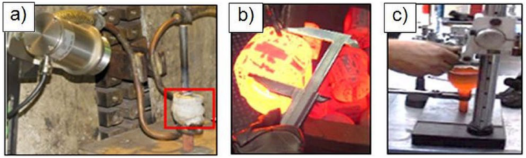
Measurement of a hot forging: (a) hook preform and view of it after forging, (b) flange forging and (c) height measurement of the forging casing of a constant velocity joint body (CVJB)
The input material can be heated both in its whole volume and partially. An example of a local heating of initial material by induction heating of a hook preform to transfer of concrete block at a build is given in Figure 4(a) . In the analyzed case, a problematic aspect was the unstable heating temperature of the preform, which was connected with its improper temperature control. With the purpose to solve this problem, Gronostajski et al. 33 developed and built a control measure station equipped with a pyrometer with a scope and a recording system, owing to which the heating temperature of the preform was set on the basis of an online measurement, with a compensation and an automatic heating shutdown, as well as an audiovisual signal given to the operator.
Within the numerous researches, the authors lead among others a research on the verification of the correctness of an induction heater after its regeneration. This is a very important step in forging technology.40,41 Detailed studies focused on determining whether the initial billet is heated uniformly in the whole volume (by the regenerated copper inductor) and not the “skin effect.” For this purpose, a set of preforms with holes for thermocouples made in various areas was prepared. Then, after heating of input material in regenerated heater, just after slipping it from the downpipe on the table, thermocouples have been mounted into it ( Figure 5(a) ) and temperature measurement was done using the measuring system UNISYS (built by authors), as shown in Figure 5(c) . In addition, numerical modeling (by Marc Mentat 2010) was carried out and included to demonstrate temperature distribution in the preform in selected areas ( Figure 5(b) ).
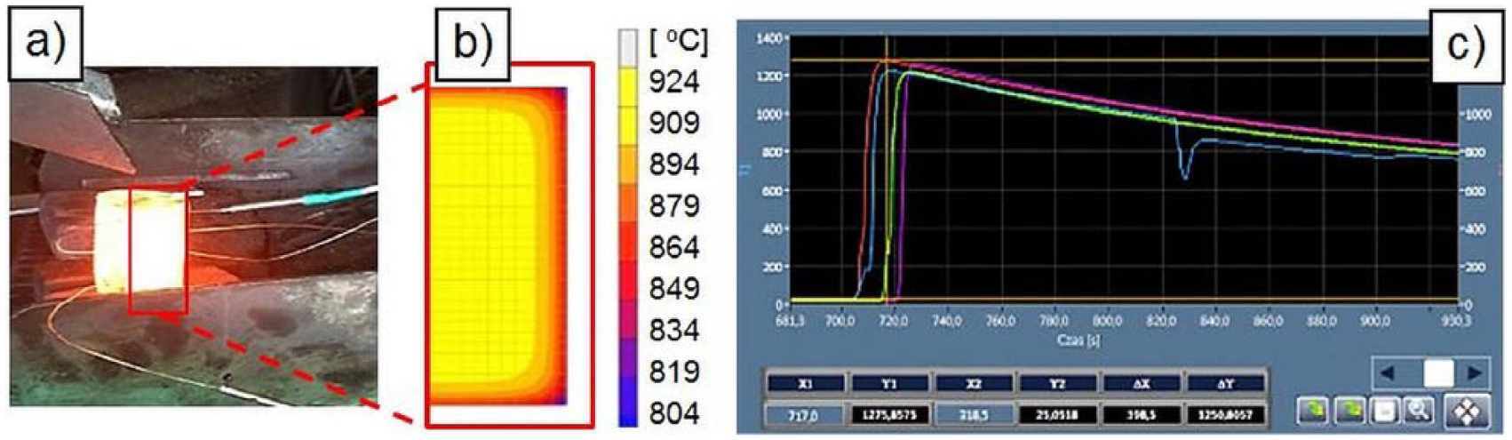
(a) The heated billet with thermocouples, (b) analysis of temperature distribution from MES and (c) the results of the measurement system UNISYS 33
The study confirmed the proper temperature distribution and hence the correct regeneration heater. Cold forging (with the flash), with specific number of pieces or at a specific time interval, was subject to a dimensional analysis during production, or as in the case of control, the ready product is analyzed in a laboratory by means of gauges, universal measuring instruments or, in special cases, CMT.
Sometimes, in the case of responsible forgings, for example, designed for the automotive and the aircraft industry, when 100% control and high shape–size precision are required, for example, in the case of thin elements, specially constructed measuring instruments are applied, in order to check all the key geometrical characteristics of the given product. Gauges are used in the case of controlling the measuring characteristics of the shape of the determined contour and surface, for complicated shapes of the contours and surfaces of nominal elements, when the application of the universal metrological tools is difficult or even impossible due to the complexity of the measuring characteristics and the assumed reference bases. An example of such a measurement is shown in Figure 6 , where one can see application of inspection techniques for the key characteristics of the shape of the determined contour and surface of the forging with the use of virtual gauges with partial bases in the PolyWorks environment (reverse engineering and inspection software for 3D digitizers for rapid prototyping, 3D modeling, inspection etc.).
A view of virtual gauge with partial bases constructed in PolyWorks environment for the key shape characteristic control of the determined contour and surface
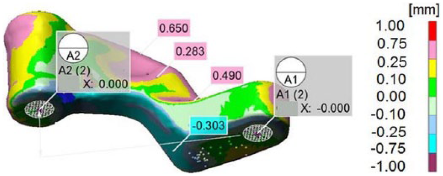
In the forging quality control process, more and more often measuring arms equipped with 3D scanners are successfully applied. Currently, the authors cooperating with forges carry out measurements and research using optical scanners and laser to analyze the geometric features of forgings and tools. Indeed, for these purposes, use CMT measurements, which, unlike scanners are more precise, but much less efficient, particularly in the case of a CAD model of the object being measured. Figure 7(a) shows a forging of piston (automotive part) made from lead on the base of research using numerical modeling—QForm (commercial FEM software) and physical modeling, for which the authors designed forging technology, additionally.
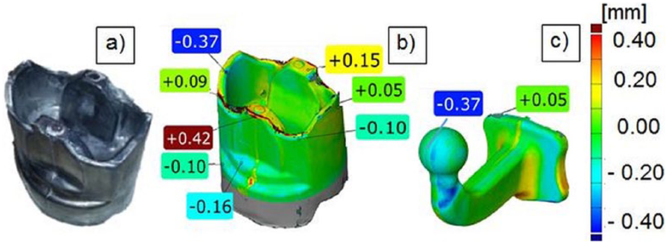
(a) The piston forging made from lead by way of physical modeling, (b) scan results of piston forging based on research using numerical modeling and (c) scanning results
Figure 7(b) and (c) shows the results of the measurement of the shape lapse of the determined hook forging and automotive piston forging surface. In both cases, authors used additive informatics tools, such as numerical ( Figure 7 ) and physical modeling to check and design a new technology, which is currently applied in forging. 37
III. Measurements and Control of Forging Instrumentation
For the control of the forging instrumentation, the same measuring tools and instruments are used as in the case of forgings. Hot tools are tested very rarely. During hot die forging, the tools undergo very high cyclic thermal (from 80 to 600 °C) as well as mechanical (0–800 MPa) loads. As a result of such disadvantageous working conditions, the tools are characterized by instability and a relatively low life. That is why dies, stamps, pads and pushers are especially closely controlled before the forging process, as it is their precision, quality and initial surface state which largely determine the shape and quality of the forging. Measurements of forging tools are also more and more often performed during and after their operation with the purpose to analyze the proceeding effects of tool wear. Such information is very crucial, especially in the case of predicting the life of the forging instrumentation. For the so-called “receipt” of small tools, coordinate measuring machines are used, which are characterized by high accuracy, that is, ±0.002 mm. In the case of large-sized tools, for which the production technology provides more tolerance due to their mobility and high measurement rate, measuring arms with integrated scanners are used, which assure the measurement accuracy of up to ±0.03 mm. Regarding the determination of the surface quality, profilometers and coarseness meters are applied. Often, in the case when the quality of the tools does not have any high parameters (especially in the case of large-sized forging tools), mobile scanning arms are used, which, besides the geometry measurement, provide the possibility of a simplified measurement of the surface waviness parameters, especially in the case when it is important to obtain an image of the whole tool in a short time.
Figure 8(a) presents a measuring station for laboratory tests use the ROMER Absolute Arm 7520si with an integrated laser scanner. Figure 8(b) shows the scan results of the punch used in the fourth operation in the multioperation forging process of CVJB housing after 4000 pieces (measuring accuracy of scanner is ±0.025 mm).
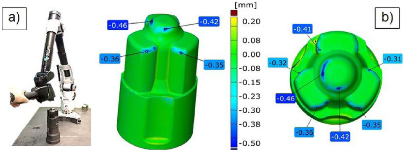
(a) Measuring station for laboratory tests with the ROMER Absolute Arm 7520si with an integrated laser scanner and (b) the scan results of the punch after 4000 pieces
Other observed phenomena, visible on the scan, are probably traces of sticking foreign material (oxide and remains of lubricant in the middle), which may indicate the presence of the adhesive mechanism. More and more frequently scanning techniques used during the regeneration of tools by pad welding involve covering the worn surface of the additional layer with an adhesive material ( Figure 9 ).
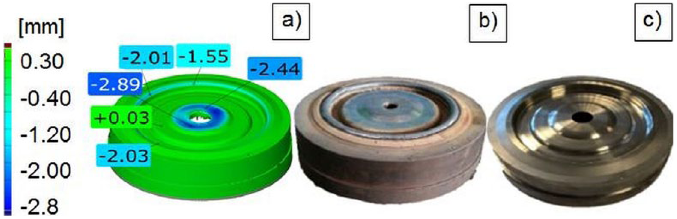
(a) View of the worn tool for disk forging, (b) tool after removing the damaged surface layer and pad welded and (c) tool after regenerative pad welding—there were no gaps of material padding welds
Therefore, it is very useful information if during the pad welding regenerative process appropriate amount of weld material in areas where it was intentionally removed was applied. Tools after the regeneration process are subjected to mechanical finishing and quality control, to check whether their shape after regeneration is in accordance with the documentation.
Applying a mobile measuring arm equipped with a scanner can be much more advanced and not necessarily performed at a laboratory, but, rather, directly, during the production process, for example, as a continuous evaluation of the state of the forging tool, that is, its life.
The authors performed measurements of the wear of a selected forging tool, which consisted in cyclic measurements of selected forgings directly during production, and additionally, they verified the results by way of a short analysis of the state of the given tool during the short technological breaks, without the necessity of its disassembly. Figure 10 presents the comparison of the scans of the forgings and the corresponding tools aimed at presenting the increasing areas of wear during the operation. 9
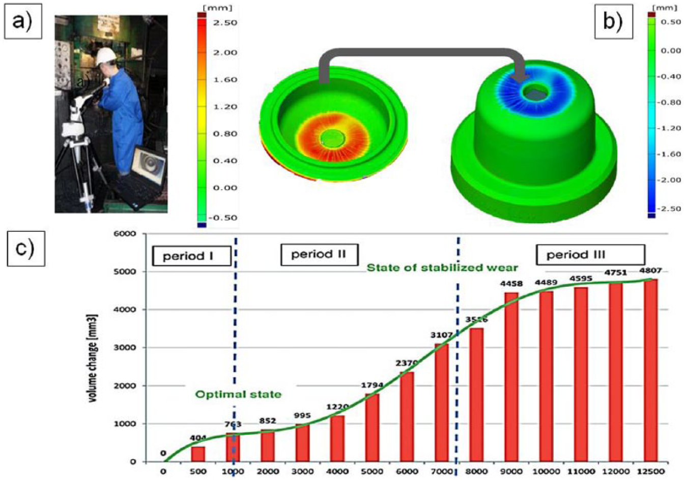
(a) View of tool with a measuring arm performed directly in the production, (b) comparison of the scans of the internal part of the forgings and the corresponding tools, in the form of qualitative geometry changes and (c) comparison of the material loss (volume changes) in the tool based on the volume changes of consecutive forgings 9
In the analysis of the volume growth in the case of the forgings and the volume reduction in the case of the tool, one can assume that they are both at a similar level. The slight difference in the obtained results is caused by the measuring accuracy of the scanner as well as the temperature difference of the scanned elements (filler temperature—about 120–150 °C, forging temperature—ambient). Figure 10(c) shows a diagram with a comparison of the material loss (volume changes) of the filler on the basis of the volume changes (adequate growth) for the consecutive forgings from a given series. On the basis of the presented diagram ( Figure 10(c) ) resembling the classic wear curve (Lorenz curve), we can observe interesting relations and distinguish a few ranges (periods) of wear. The classic Lorenz curve, toward the end of the period of normal operation, usually turns into the state of accelerated wear, which, unfortunately, cannot be observed in the analyzed case. This can be explained by the reduced pressure exerted on the tool as a result of the proceeding wear of the contact surfaces of the tool and the formed forging.
Next, the application of non-contact measurement can be control of forging tool wear in selected areas. In some cases, the total material loss of forging tool does not give a complete “view.” In the case of a comparative analysis of several such tools, errors may occur, resulting, for example, from tool breakage or premature wear of one of the areas which causes disturbances in counting the volume of material loss. Figure 11 shows the image with die inserts divided into two selected specific areas (A and B), which on the basis of a preliminary analysis showed the presence of various destructive mechanisms. In addition, the analysis by 3D reverse scan showed that on the basis thereof much more rapid wear of the forging tools in the area A can be seen (a new tool cross is made in this area which acts as marker 42 ).
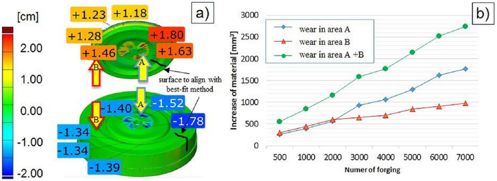
(a) The idea of scanning 3D-reverse scanning method—the division on selected areas and (b) the results of the tool wear analysis in selected areas, based on cyclically collected forgings 42
As you can see in Figure 11(b) , the wear of A and B is nearly equal to 2500 forgings. Above this number, wear increases intensively on the inset face (area A), relating to wear on the bridge (area B). Therefore, an analysis of the total consumption inserts was conducted and it may be subject to errors due to the different intensities of wear of the tool in different areas.
A crucial parameter in the forging process, both due to the tool life and the quality of the finished product, is the temperature. This is applied especially to narrow the tolerance zone die and small spacing between the moving gear units. Indeed, as a result of thermal expansion, the material can experience a change in the dimensions of one of the components, which may in turn cause blockage of the tool. Pre-heating is important in the context of tool durability. At a lower temperature, steel is characterized by worse toughness, and therefore, a “thermal shock” caused by large temperature gradient between the heated input material and the tool can cause brittle fracture. For example, analyzed by the authors, in the Yoke forging process, the maximum temperature on the surface of the tools was 160 °C ( Figure 12(a) ), which is about 90 °C below the recommended temperature given in the card technology. An important issue in regard to the accuracy is that it is also a method of temperature measuring. Measurement using a thermovision camera or pyrometer refers to the temperature of the surface of the object and can be additionally burdened with an error resulting from a fixed pre-set of emission values in these devices (usually 0.95). In fact, due to dynamic temperature changes during the forging process, the radiation of object factors is variable. Often, calibration instruments for non-contact measurement comprise of a contact sensor—thermocouple ( Figure 12(b) ). Therefore, the most accurate is the contact measurement using thermocouples, which unfortunately, in the case of industrial forging processes is very difficult or impossible.3,4,33
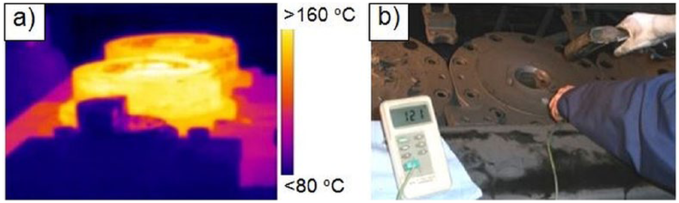
(a) Thermogram with the temperature of the die inserts and (b) a verification device to measure the temperature of the forging tools
The appropriateness of the shaping process largely depends on the used lubricant, the task of which is not only lubrication but also cooling of the tools. In order to analyze temperature changes in the forging die during forging, the authors constructed their own measuring system and performed a measurement of the temperature of the tools with the use of a thermocouple introduced into the die through a special groove ( Figure 13 ).
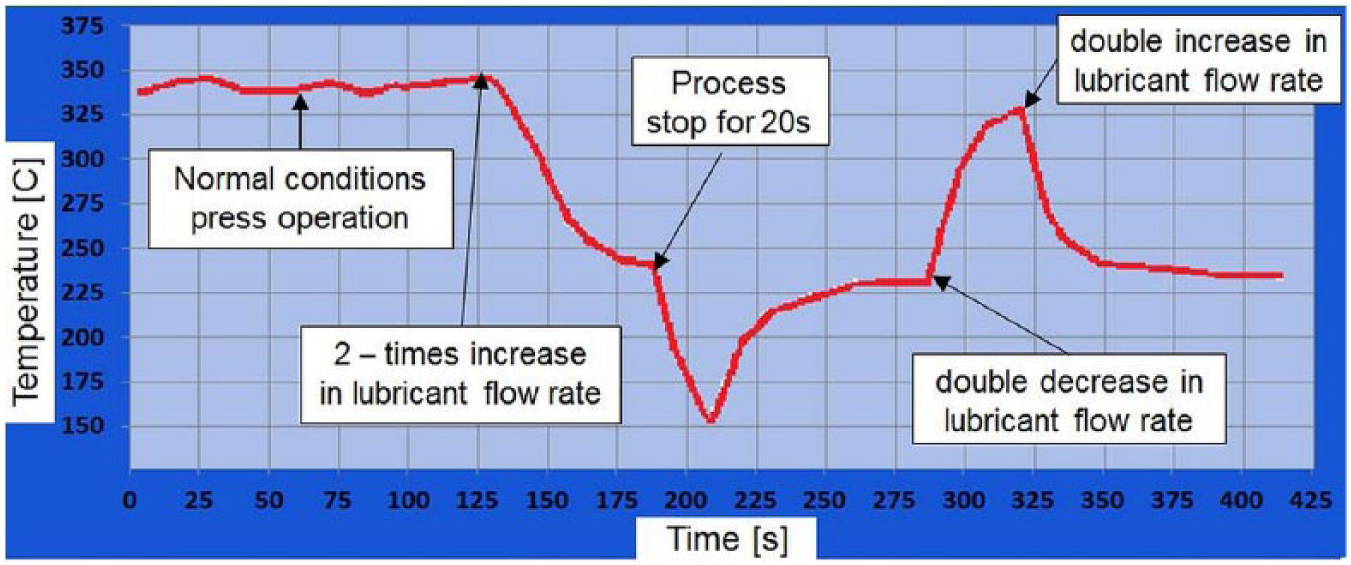
A view of change temperature of die during forging with the most frequently occurring process disturbances marked 33
The conducted research concerning the impact of the amount of cooling—lubricating agent on temperature changes, at a distance of 10 mm from the worked hollow of die, showed interesting results. The measurement showed that a twofold increase in the expenditure of the lubricant reduces the die temperature to about 100 °C.
Currently, the authors use the scanning method to analyze the durability of forging tools, which are often combined with macroscopic analysis, as one of the stages of the comprehensive study, among which are conducted additional research of the microstructure, micro-hardness measurements, numerical modeling and other.
This comprehensive approach to tool life allows a better and more complete analysis of the causes of premature wear of forging instruments.7,11,43–45 Figure 14 shows exemplary results of complex tool analyses. Conducting a comprehensive analysis showed that for the selected die insert, the main destructive mechanisms are abrasive wear (observed on the rays, where it was most intense material flow) and mechanical fatigue (seen around the pin). Micro-hardness measurements showed no significant changes in the surface layer, in the analyzed area of insert. The results of numerical modeling showed that the greatest normal pressure from the deformed material is present in the area of the hole ejector. The whole working surface of the insert shows the first traces of thermo-mechanical fatigue, in the form of a fine grid of cracks. Analyzed die insert worked of 6000 forgings. Probably, the greater the amount of forgings, the larger the primary grid of fatigue cracks and there would be a secondary grid of cracks.
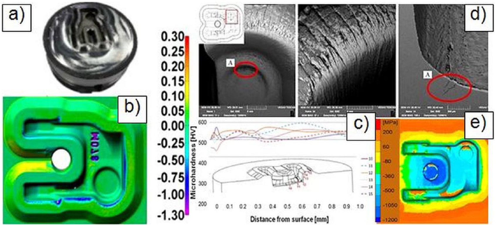
The comprehensive approach to tool life: (a) die inserts for scanning, (b) scanning result, (c) microstructure research, (d) micro-hardness measurements and (e) numerical modeling
IV. Other Measurement Applications in Die Forging Processes—Measurement and Control System
At present, industrial forges to manufacture a given product often use old machines, without monitoring systems of the working parameters, which, due to their age, easily fail, and the wear of the cooperating movable elements, as well as the clearances, causes big problems in stabilizing the production process. Additionally, one should consider the character of the forging process and the relatively low life of the forging tools, connected with their wear, due to big temperature changes and high pressures. For financial reasons, forging plants rarely decide to purchase a new device dedicated to a specific production line. The commonly applied forging machines and devices are usually equipped with simple control and measurement systems, which merely allow the control of the maximal forging force, the machine’s work speed, the number of forgings and the initial temperatures of the preforms.10,12,17,25–27,32,33,46–48 Within the frames of the performed long-term research, the authors have elaborated and constructed measurement and control systems for the analysis and control of industrial die forging processes, which have been used, for example, in the process of forging catches used to move concrete blocks on an eccentric press in the TR device (INOP, Poznań, Poland) and in the process of hot forging of a constant velocity joint body joint casing on a crank press in closed dies (GKN Driveline, Oleśnica, Poland).25,26 The elaborated systems are built of an industrial computer (a real-time controller, a fast multi-channel measurement card, an operational memory chip, high capacity hard disks, a set of amplifiers and converters) and appropriate measurement sensors (of the force, shift, pyrometers, thermocouples, encoders, accelerators, piezoelectric sensors etc.).
The calibration process, which has been the subject of a few years of research, is fully recognized and it guarantees obtaining accurate measurement results. The commonly applied calibration methods assume calibration with the use of hydraulic actuators, which stretch the body of the frame, or forging (upsetting) metal cylinders of the appropriate size and known material. These methods, while justified, do not provide good results, mostly because they are performed under static conditions and they require completing additional actions. The force measurements are made directly by means of tensometric strain gauges, extensometers glued to the press columns as well as sensors based on the piezoelectric phenomenon and the systems integrating the charge ( Figure 15 ). All the signals, after conditioning in the measurement area, which guarantees resistance to interferences caused by the presence of drivers and the induction heater, as well as the interferences coupled on the supply network, will be transmitted to the measuring server, which, in turn, will send them to the main server, at the same time determining the parameters for the control system of the machine and the production process, constituting the superior (IT tools, or informatics tools) system of production management.49,50
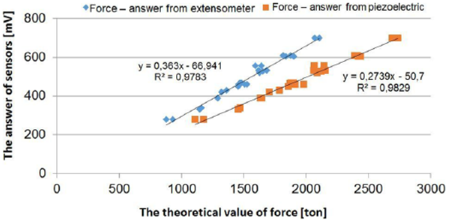
Results of measurement system calibration for tensometric gauges and piezoelectric sensors
Also, tests with the use of the elaborated measurement system for the analysis of the acoustic emission (AE) signal were performed. The tests included the process of forging a catch for moving concrete blocks, realized on an eccentric press in the TR device in INOP ( Figure 16(a) ).
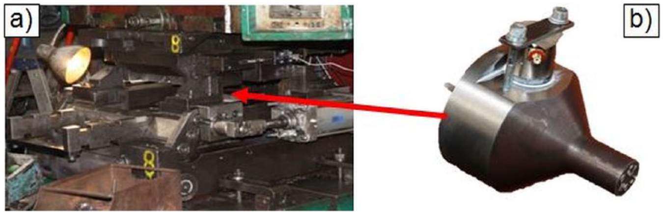
(a) View of the TR device and (b) punch with an AE sensor 26
The system was used for the pioneering research of the AE signal, which allowed for the determination of the wear of the tools used in the second and third operations of forging the catch. The tools were equipped with AE sensors ( Figure 16(b) ). The sensor mounted on the surface of the punch receives elastic waves, which originate from other parts of the machine as well as from the treated material.
The AE events are plotted on the force diagram corresponding to the analyzed forging operation ( Figure 17 ).
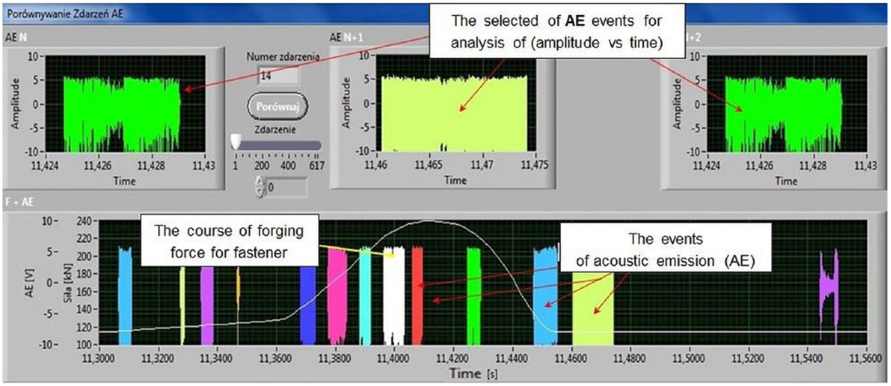
View of the main panel for the analysis and selection of acoustic emission events occurring during forging process 25
After the verification of most of the AE events, it will be possible to search the signal and recognize the new occurring events and next replace the broadband sensor with a resonance one. The narrowing of the signal frequency will increase the signal sensitivity, thus detecting the events responsible for the microcracks of the punch material or its wear.
The authors are also planning to design an IT system which will play a supervisory role over the whole process. Monitoring systems, such as SCADA (supervisory control and data acquisition) or similar solutions, like ANDON (comes from Japanese automobile manufacturers and means light signal calling for help), are commonly available, being implemented by many companies.49–51
The reason for this is the lack of specialized solutions adapted to the needs of the particular production processes implemented by companies with a high understanding of the problem and the values of the given process indicators. Integration of all the production stages and the supervision of the production machines in one superior system elaborated by a consortium specializing in forging and measuring technologies is introduced. The elaborated superior system will also allow for an analysis of the recorded parameters throughout a long period of time, which provide the possibility of development in the area of applied technology, of management of equipment resources (machine work, breakdowns, repairs etc.) and the human resources, as well as adaptation of the production organization to the increasing market demands. Using high-performance computing machines, real-time systems, many parameters and analyses will be made on the spot measurements. This will ensure the independent operation of each of the subsystems, some functionality, and make subsystems independent of failure of other components of the position.
V. Summary and Final Conclusion
A typical technological process of die forging consists of many stages, including material delivery from the plant, its cutting, heating and forging, as well as a thermal treatment of the final product. At each of the mentioned stages, there is a potential risk of an error causing a forging flaw. A properly designed and implemented forging process, which allows for the production of a repeatable series of forgings without flaws, requires the selection of optimal technological parameters, such as a proper design and manufacture of tools and an optimization of the preform shape and arrangements for their optimum temperatures. As it has been proven in numerous articles and elaborations, the parameters affecting the die forging processes undergo complex interrelations, which significantly complicate the analysis of the forging processes. The extreme conditions in industrial processes hot forging (high cyclic mechanical loads and temperature gradients on the surface of forging tools) cause that old but reliable equipment is still used. It allows to quickly, accurately measure the specific geometric feature, because the measurement of any other method or device gives rise to many problems or is impossible to carry out. On the other hand, it should be also clearly emphasized that the industrial forges, although they are aware of the need of quality control, often due to financial aspects, do not attach sufficient importance to the instruments and measurement methods, especially in the context of safety (achieved forgings used on the responsibility of machine parts, for example, for the automotive industry).
Currently, using different measuring methods and specialized equipment and tools of computer-aided measurement, advanced measurements can be carried out and analyses of forgings, status of tools and machinery forging can be performed. The presented ways of controlling the quality of forgings and forging instrumentation are largely perfected by the geometrical specification, symbolically recorded in the form of technical drawings, which constitute the basis for the elaboration of the appropriate process of forging production in the die forging technology. The geometrical specification of the given products specifies not only the rules of selecting the measuring equipment for the forging quality control but also those of selecting the tool necessary for the control of the dies used in the forging process. It is worth noting that the way of performing the measurements is determined in each production stage by the chain of operations aiming at maintaining a coherent quality control system according to the existing normalizing system. In the forging production process, different measuring methods are used, from methods using the universal measuring equipment assuring a lower measurement accuracy, for the control of the key geometrical characteristics on a hot forging, to more complicated measuring techniques using the universal measuring equipment combined with specially designed gauges, which allows for a full quality control on cold forgings of a non-complicated geometry, to measuring methods based on CMT for forgings of a complicated geometrical specification. Modern CMT methods allow for a full size control of even most geometrically complicated forgings, forging tools and other elements of forging tools.
One can also notice new trends, which are related to the possibility of using portable measuring systems, such as optical scanners and linear scanners mounted on portable measuring arms. This technology allows for a quality control of forgings of medium and large sizes, as well as forging tools of very large sizes, whose measurement takes place directly during production, or those of a very small geometry (the size of a paper clip), as well as for performing measuring steps which, so far, have been neglected or performed sporadically, often with the use of the universal measuring instruments. At present, these techniques are commonly applied for such purposes as analysis of the shape of precise (very small) forging stamps used in the big lot production of small details, such as screws, as well as analysis and correction of shape after the tools’ assembly on the forging aggregate, and also evaluation of the technical state of the forging machines and devices. The performed research with the use of a measuring arm, together with an integrated laser scanner for the analysis of the filler wear, on the basis of the measurements of the shape changes of consecutive forgings (directly on the production line) proved the validity of applying new measuring technologies in order to directly analyze the quality and change of the tool shape (without disassembling the instrumentation from the forging unit). Owing to this, such an analysis was possible directly during the production process.
It should also be noted that, year after year, the level of awareness connected with the measurements and quality of the product and the forging tools is constantly rising—not only at modern forging plants—which leads to an increasing focus on using better and more precise measuring instruments, as well as applying new measuring methods. Such an approach stimulates the development of workshop techniques and metrology, the use of which will be connected with new fields from outside the forging industry.
Footnotes
Funding
This study was funded by National Centre for Research and Development, Poland (NCBiR); grant no. POIG.01.04.00-02-056/13.