
Abstract
In this study, an expendable current profiler sensor is developed to satisfy the actual requirements of an expendable current profiler for measuring electric fields induced by ocean currents. The electric field induced by ocean currents is an important process variable for investigating the motion characteristics of ocean currents; however, accurate measurement thereof is affected by various factors. Amplitude modulation is used to modulate the measured signals into narrow-band, single-frequency signals, thereby reducing the noise level of the sensor when measuring the electric field induced by ocean currents and for extracting ocean current signals in the nanovolt range under high background noise. In this study, front-end weak signal processing circuits are designed, strong interfering signals induced by the descent of the expendable current profiler probe are partially offset by a compensation circuit for the in-phase electric field component, and useful signals are extracted using a filter circuit. System on a programmable chip technology is used for the digital processing module of the expendable current profiler probe, thereby achieving rapid development, rapid optimization, and software/hardware integration of the digital processing module, as well as enhancing the overall performance of the system. In addition, dynamic data transmission technology using an enameled wire with a diameter of 0.1 mm and a length of 2 km is developed to achieve dynamic data transmission requirements for the expendable current profiler surface float. Finally, the ocean current electric field data and ocean temperature data are acquired through experiments.
I. Introduction
Oceanographic studies require accurate, real-time information about the velocity of ocean currents. Detailed information about the velocity of ocean currents can be calculated by determining the ocean current–induced electric field generated by ocean currents moving through the geomagnetic field.1,2 Therefore, the measurement of ocean current–induced electric field is very important for studies related to the motion characteristic of ocean currents.3–7
The electromagnetic induction theory was proposed by Faraday in 1832. Based on this theory, a method for calculating the velocity of ocean currents through an ocean current–induced electric field was proposed. Sanford 1 proposed the basic calculation equation for motion-induced electric and magnetic fields in the sea in 1971. After several years of intensive studies, they successively designed several generations of devices such as the electromagnetic velocity profiler (EMVP) in 1978, 8 the expendable temperature and velocity profiler (XTVP) in 1982, 9 the absolute velocity profiler (AVP) in 1985, 10 the multi-scale profiler (MSP) in 1996, 11 and the electromagnetic autonomous profiling explorer (EM-APEX) in 2005. 12
Excepting the XTVP, which is an expendable type of probe, the above devices are all recoverable. When measuring, the apparatus sinks due to its hung weight and measures parameters such as ocean current while sinking. After the measurement is completed, the apparatus emerges to the sea surface by releasing the weight. At the same time, the measured data can be transferred back wirelessly. Because of the recoverable nature of these devices, more components can be incorporated to achieve more functions. For instance, an acoustic Doppler device can be added to measure the absolute velocity.
The expendable current profiler (XCP) is an inexpensive disposable ocean current profile observation device that can quickly acquire parameters for measuring the seawater velocity profile. With an added float to achieve the wireless data transmission function, it can be launched from an aircraft, a ship, and a submarine. The XCP can be used to measure various profile parameters such as water temperature and ocean currents during the course of its rapid descent, and it can calculate water depth parameters based on the descent velocity and descent time. The measured data are transmitted to the carrier platform wirelessly, and real-time information about the variations in profile parameters, such as water temperature and ocean currents, with respect to different depths, can be obtained through data processing. 13
XCP still has great practical value because of its advantages of low cost, convenient and fast operation, and real-time measurement. Currently, only a US company, Sippican, owns the XCP technology and manufactures the related instruments. However, its products have not been updated since 2005, and they are prohibited to be sold in certain countries. Therefore, it is critical to conduct in-depth studies on the XCP technology and promote further development of this type of instrument.
There are several difficulties associated with XCP-based measurement of the ocean current–induced electric field: measurement of ocean current–induced electric field signals in the nanovolt range under high background noise, extraction of effective signals under the strong interference caused by the electric field induced by the descent of the XCP probe, and the requirement of dynamic special data transmission technology with enameled wires. Therefore, in this study, according to the aforementioned problems, an intensive investigation was performed considering the following aspects: design of the front-end circuit of the probe, design of the digital processing module of the probe, and dynamic special data transmission technology with enameled wires. Finally, an XCP for measuring ocean current–induced electric field was designed and several marine tests were performed.
In section II, the equation of induced electric field and the XCP detection principle are described. The overall framework of XCP devices is explained in section III, and the design of the critical XCP components is detailed in section IV. Section V presents the marine tests of the proposed XCP, and section VI concludes this technical exploration.
II. XCP Detection Principle
Ocean currents cut through the magnetic flux lines of the geomagnetic field, inducing electromotive force and electromagnetic fields. Under a steady geomagnetic field, the magnitude of the induced electromotive force depends on the velocity of ocean currents. 14 Therefore, the motion characteristics of ocean currents can be investigated by measuring the induced electric field. Because the horizontal flow of the ocean currents is much stronger than its vertical flow in most cases, most studies focused on horizontal ocean currents.
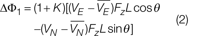
In a rectangular coordinate system with the x-axis (east), y-axis (north), and z-axis (vertical), an ocean current with velocity V flows horizontally in any direction, and there is a measurement direction angle θ between the induced voltage direction and the y-axis. The electromotive force ΔΦ1 induced by the ocean current, measured between two points separated by a distance L on horizontally placed electrodes, is given by the following equation 8
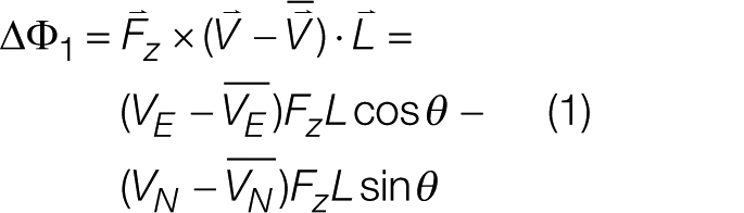
where
III. Overall Framework of XCP Devices
An XCP device mainly consists of a probe, a float, an enameled wire with a length of several thousand meters for data transmission between the probe and the float, and an XCP wireless ocean current data on-deck receiving unit; its operation principle is shown in Figure 1 .
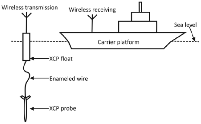
Operation principle of expendable current profiler
To measure the velocity of ocean currents at different depths, the XCP probe normally descends freely and measures the current velocity profile at a certain point from the sea surface to the bottom of the sea during its descent. 8 When an XCP is launched into the sea, the float senses the seawater and triggers the release switch to release the probe. The probe then drags the enameled wire (double strand enameled wire with an outer diameter of 0.1 mm and a weight of approximately 300 g per 2 km) and quickly descends while rotating. Meanwhile, the probe continuously acquires ocean current–induced electric field data and temperature data at its location. These data are transmitted to the surface float through the enameled wire in real time and then it is relayed by the wireless device in the float to the wireless receiving unit on the carrier platform. When the probe reaches the bottom of the sea, the enameled wire is automatically disconnected, and the entire measurement process from the surface to the bottom of the sea is completed.
The overall XCP framework is shown in Figure 2 , and the hardware development for XCP mainly focuses on circuit designs for the probe, float, and on-deck receiving units. The analog circuits for the probe include analog signal conditioning circuits for various weak signals (Ag-AgCl electrode signals, compass coil signals, and temperature signals), a voltage comparison circuit, and an A/D conversion circuit. The digital circuits for the probe mainly include a voltage/frequency (V/F) conversion circuit and a system on a programmable chip (SOPC) digital circuit. The circuits for the float include a data-receiving circuit and a wireless transmission module. The on-deck receiving unit includes a portable data storage host computer and a wireless receiving module.
Overall structure of XCP
In the development process of these components of XCP, some critical technologies need to be studied intensively, for example, ocean current electric field sensor, front-end weak signal processing circuits, digital processing technology, dynamic data transmission technology, and ocean current data processing.
IV. Critical Technologies for XCP Devices
A. XCP ocean current electric field sensor
An ocean current electric field sensor is the front-end sensor unit for an XCP, and its properties directly affect the overall performance of the XCP. 14 Because the strength of the electric field induced by ocean currents moving through the geomagnetic field is very weak, a 1 cm/s ocean current in low- and mid-latitude regions can only generate an induced electric field of less than 1 µV/m. 8 When designing a portable XCP to achieve a precision of 1 cm/s, the length of the ocean current electric field sensor should normally be set to 5 cm and its noise should not be greater than 50 nV.
The marine measurement environment is designed such that the ocean current electric field signals inevitably undergo a process of transmission from the liquid phase to the solid phase. When media in different phases interact with each other, electrochemical noise is generated; this adversely affects the observation of the weak electric field signals induced by ocean currents. Thus, it is essential to use an electrode material that has small and steady polarization potential in the marine environment. Numerous tests have shown that electrodes prepared from Ag-AgCl according to a certain ratio using powder metallurgy technology exhibit excellent electrochemical properties in seawater for the following two reasons. First, pure silver can be readily obtained under laboratory conditions, and the “battery effect” can be eliminated. 15 Pure silver also has excellent electrochemical stability in environments with essentially unchanged temperature. Second, the conductive component of seawater is Cl− ions. When AgCl comes in contact with seawater, the major conductive substance on the interface between the solid phase and the liquid phase is the same chemical component, which minimizes the electrochemical noise.
B. Design of front-end weak signal processing circuits for the XCP probe
To design front-end weak signal processing circuits that meet the performance requirements for the XCP, the properties of the front-end sensor and the characteristics of its output signals need to be identified before designing the probe.
The potential difference between two electrodes of the ocean current electric field sensor is less than 1 mV with a fluctuation of less than 0.1 mV/24 h. 15 Although the potential difference and its variation are very small, its interference is 10,000 times the strength of the ocean current electric field signals in the nanovolt range. To reduce ambient noise in the ocean current electric field signals and increase the signal-to-noise ratio, the electric field signals need to be modulated into narrow-band, single-frequency signals using AM modulation for subsequent phase-lock amplification and extraction.
The sensor of the XCP probe consists of a pair of non-polarizable Ag-AgCl electrodes and a compass coil placed coaxially with the electrodes. As the XCP probe descends into the sea, the rotary wings on the tail portion drive the electrodes and the compass coil inside the XCP probe to rotate at the same angular velocity and cut through the geomagnetic field thereby generating electrode signals and coil signals. However, the electrode signals are superimposed with two types of signals: ocean current–induced electric field signals superimposed into the electrode after modulation and the induced electric field signals of the XCP probe generated by the electrode cutting through the horizontal magnetic lines of flux during the course of descent.
Assuming that the electric field induced by a 1 cm/s ocean current in the region of northern latitude 20° generates a voltage difference of approximately 20 nV on the ocean current electric field sensor (inter-electrode spacing of 5 cm, descent velocity of 3.85 m/s), the strength of the electric field induced by the descent of the XCP probe is approximately 7.3 µV. This indicates that the induced electric field signals are strong interfering signals. The functional block diagram for the front-end weak signal processing circuits of the ocean current electric field probe is shown in Figure 3 .
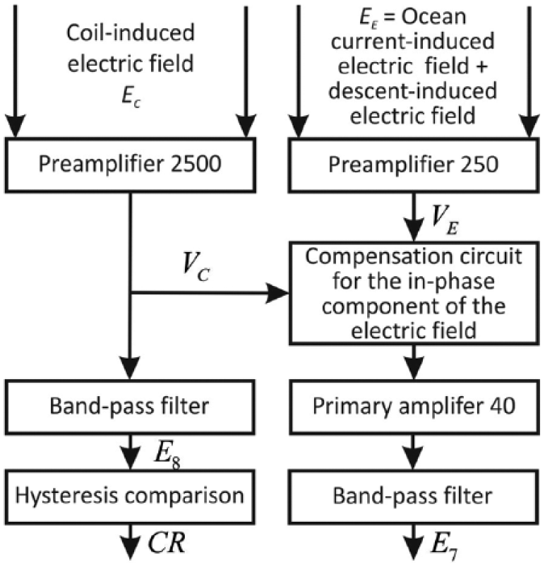
Weak signal processing circuit functional block diagram of the XCP probe
As shown in the figure, the compass coil signals play two roles: (1) determining east and north directions and (2) offsetting the electric field induced by probe descent. The front-end weak signal processing circuits for the ocean current electric field probe mainly include preliminary amplifiers used to amplify ocean current electric field signals and compass coil signals 250 and 2500 times, respectively; modulation circuits for modulating ocean current electric field signals and compass coil signals into approximately single-frequency signals with a frequency of approximately 16 Hz; a second-order band-pass circuit with a center frequency of approximately 16 Hz for the probe to extract signals effectively; and a compensation circuit for the in-phase component of the electric field, used to partially offset the electric field signals induced by the descent of the XCP probe.
C. XCP probe digital processing technology
The method of digitizing the extracted ocean current–induced electric field signal is also a key question in the XCP design. In EM-APEX, a 24-bit A/D conversion method is employed, which can achieve very high precision. 12 However, for the weak signal processing circuit used in the present design, a sampling rate of at least 5760 bps is needed to achieve an angular resolution of 1 degree. If two 24-bit A/D converters are used, there will be at least 276,480 data bits generated every second. However, in the sea, the data transmission technology for twin enameled wires cannot achieve such a high data transmission speed. Therefore, this method is not suitable for the present design. In XTVP, the FM modulation method is employed, in which the extracted ocean current–induced electric field signal is voltage-to-frequency converted, and then is transferred to the receiving unit on the deck, where it is demodulated. 9 A similar method is employed in the present design, but it is improved by introducing the SOPC technology to the XCP probe. Now, the digital signal processing is carried out inside the probe, so that the data volume can be compressed into an achievable range for the data transmission module. At the same time, the digital signal transmission can be directly carried out over the thousands of meters of the enameled wire between the probe and the float. In this way, the anti-interference ability of the data transmission is strengthened and thus the measurement precision is improved.
SOPC technology was used in the digital processing module of the probe to integrate HDL programming, construction of the soft processor, and soft processor-oriented C programming into the XCP design. This helped in achieving rapid development, rapid optimization, and software/hardware integration of the digital processing module of the probe, and in enhancing the overall performance of the system. The digital processing module of the probe mainly includes four components: (1) digitization technology for subsequent processing of the analog signals of the ocean current electric field and the compass coil, and HDL module-based digital processing and effective information extraction technology for the signals; (2) AD conversion of ocean temperature data and realization of the HDL control program oriented to the AD conversion chip; (3) construction of NIOS II soft processor oriented to the XCP probe module, and its on-chip peripherals; and (4) NIOS II-based C programming for the control of the aforesaid hardware modules and effective uploading of data.
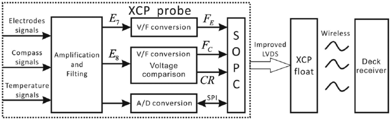
The digital processing main control board of the XCP probe was designed after comprehensive analysis and its block diagram is shown in Figure 4 , wherein the temperature signal collection circuit is integrated into the analog circuit board of the probe. The SOPC chip, SRAM, and FLASH constitute a minimal digital system. Signals E7 and E8 from the analog circuit board of the probe enter the AD650-centered voltage/frequency conversion circuit and output pulse signals Fe and Fc. E8 enters the LM393 voltage comparator circuit and outputs pulse signal CR. Signals Fe, Fc, and CR enter the SOPC chip and are processed by the HDL program to generate various parameters such as spin cycle (T), in-phase component of compass (Ic), in-phase component of electrode (Ie), compass baseline level (Bc), electrode baseline level (Be), quadrature component of compass (Qc), quadrature component of electrode (Qe), and number of spin turns. A 24-bit AD converter CS5532 is used to collect temperature data, and such data are finally sent to the float on the sea surface through a double strand enameled wire.
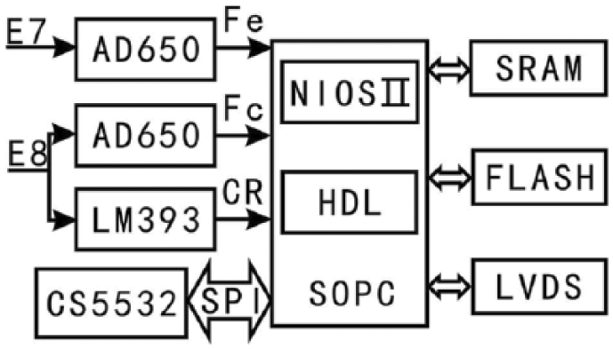
Block diagram of digital processing main control board of XCP probe
D. Dynamic data transmission technology for XCP surface float
To achieve rapid underway measurement of XCP, there should be a data relay station between the probe and the carrier platform. This relay station receives data from the XCP probe while transmitting the data to the on-deck wireless ocean current data-receiving module on the carrier platform in a real-time manner. The XCP surface float serves as the relay station.
One of the more difficult problems associated with XCP is the dynamic data transmission technology for the surface float of the XCP. The communication between the probe and the float is achieved through a double strand enameled wire with a diameter of 0.1 mm and a length of 2 km. An indoor data transmission test was performed on this enameled wire using the CAN bus technology, which is claimed to be able to transmit data up to 10 km. It was shown that an enameled wire with a length of 1 m failed to transmit data even under static condition, indicating that it is not easy to transmit data with this kind of enameled wire.
This problem exists not only in the XCPs but also manifests as a common issue confronted by all the expendable profilers, such as XCTD. In some expendable profiler designs, a baseband transmission method is employed. However, this method requires applying a high voltage of up to 60 V on the transmission wires, and once the wires become even slightly damaged, breakdown will occur, causing data transmission failure. 16 Therefore, a high-performance data transmission method will be crucial for the development of various XCPs.
The universal asynchronous receiver/transmitter (UART) protocol with 1 start bit, 8 data bits, and 1 stop bit is used as the data transmission protocol for the probe and the transmission rate is 4800 bps. The low-voltage differential signaling (LVDS) transmitter of SOPC is used as the physical layer transmitter. 17 In LVDS, the transmission manner of differential signals is employed and a current source is used to drive the device. Therefore, this transmission method has very strong anti-interference capabilities. At the same time, the data are Manchester-encoded in the driving layer in order to further improve the anti-interference ability. In addition, all of these functions are achieved inside the SOPC and thereby no additional hardware costs are incurred.
Figure 5 shows the block diagram of the physical layer of the receiver in the data transmission float. Because the enameled wire for data transmission is in a rapid, dynamic, automatic unreeling state, when the wire starts unreeling, most of the wire is entangled and inductive. During the course of unreeling, the enameled wire is in the seawater with a high dielectric constant (the relative dielectric constant is around 81), 17 and it becomes considerably more capacitive. Consequently, LVDS signals are superimposed with strong noises. To eliminate the electric connection between the enameled wire and the floats, a high gain transformer is used as the first stage of the float’s receiver unit for isolation and amplification of signals. Then, the signals enter high-pass and low-pass filters, a hysteresis comparison circuit, and analog scaling, addition, and subtraction circuits to collect and extract data for transmitting into the SOPC inside the float.
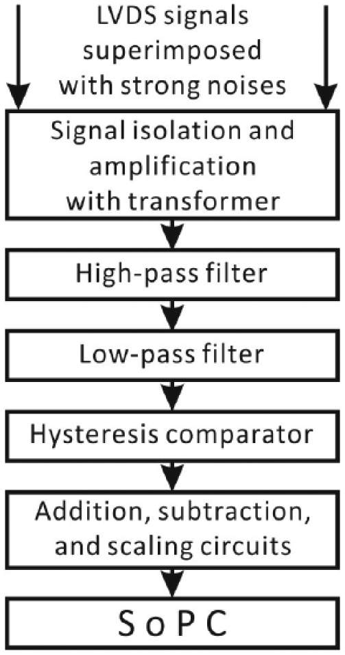
Block diagram of the physical layer for the receiver of the data transmission float
E. Wireless ocean current data receiver and data processing program of the on-deck unit
To enable the XCP carrier platform to collect ocean current data, the XCP carrier platform is equipped with a wireless ocean current receiver unit matching the wireless data relay station of the surface float. This receiver unit uploads the data to the host computer via the USB port. The on-deck unit can be equipped with two wireless ocean current data receiver modules to achieve double backup of ocean current data.
To achieve real-time measurement of ocean current–induced electric field, not only do XCP hardware devices need to be developed, but host computer software supporting such hardware devices is also required. Real-time processing, storage, and display of ocean temperature and ocean current data on the host computer were achieved using LabVIEW and Visual C++. Visual C++ works complementarily with LabVIEW to achieve identical functions, which enables double interface backup of original data to a certain extent to effectively avoid loss of original data.
F. XCP ocean current data processing
According to the model provided by Sanford et al., 8 Equation (1) is corrected by adding a compensation factor induced by the XCP probe, as shown in Equation (2), where L is the inter-electrode spacing and K is the impact of the XCP probe on the distribution of the ocean current–induced electric field around the XCP probe placed in the tested seawater. Numeric simulation, forward modeling, and physical simulation tests show that the addition of the XCP probe led to an approximately onefold increase in the strength of the ocean current–induced electric field received by the XCP ocean current electric field sensor; thus, the value of K is normally 1
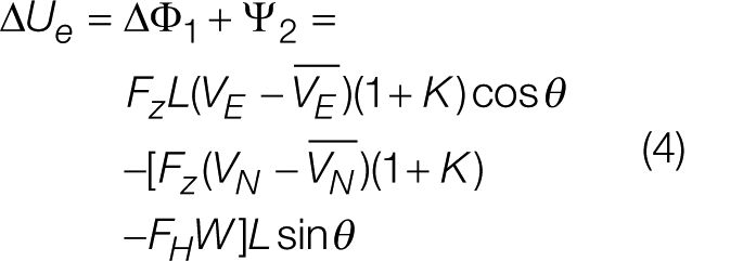
The induced electric field Ψ2 generated by two electrodes cutting through the geomagnetic field during the descent of the XCP probe is expressed by Equation (3), where FH is the horizontal geomagnetic field strength, W is the descent velocity of the XCP probe, L is the inter-electrode spacing, and θ is the angle between the measuring electrodes and y-axis (magnetic north). Therefore, the total voltage ΔUe imposed on the XCP ocean current electric field sensor is expressed by Equation (4)

Voltage signals measured by the electrodes and coil signals are converted into pulse signals by an AD 650 voltage/frequency converter where the magnitude of the voltage is represented by the magnitude of the frequency of the signal. During the course of measurement, the modulated signals are demodulated by the probe through electric circuits according to the compass coil signals and are transmitted to the surface XCP float. Next, they are relayed to and stored in the wireless ocean current data receiver in the deck unit. In fact, the main data recorded by the measuring instruments include cycle counts of useful signals and coil signals, and two types of signals are modulated into the in-phase component In, quadrature component Qn, and baseline level Bn.
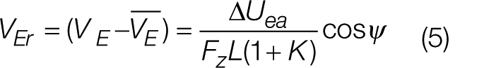
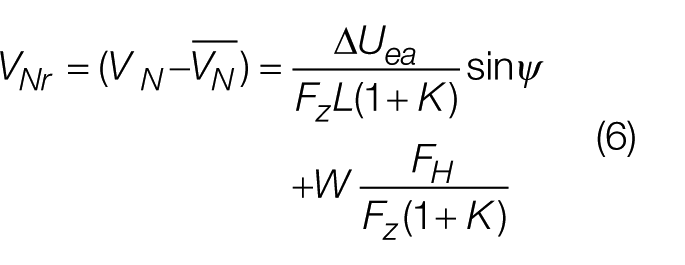
Based on In, Qn, Bn, and instrumental gain calibration for the induced electric field and compass coil channels, the amplitude and phase position of the induced voltage signals
V. XCP Marine Tests
The first marine test for the developed XCP was performed in April 2009 and four XCP probes were launched. Ocean current electric field signals within the 100 m range from N 18°37.713′, E 120°13.643′ to N 17°56.168′, E 119°36.741′ in the South China Sea were obtained by XCP probes. The second marine test for the XCP was performed between September and October 2009 and seven XCP probes were launched. Ocean current velocity data and temperature data in the sea area near N 21°56′, E 118°36′ from the sea surface to 900 m below sea level (BSL) were obtained by the XCP probes. The third marine test for the XCP was performed in March 2010 and seven XCP probes were launched. Ocean current velocity data and temperature data in the sea area near N 21°59′, E 118°10′ from the sea surface to 900 m BSL were obtained by the XCP probes. The results are shown in Figure 6 .
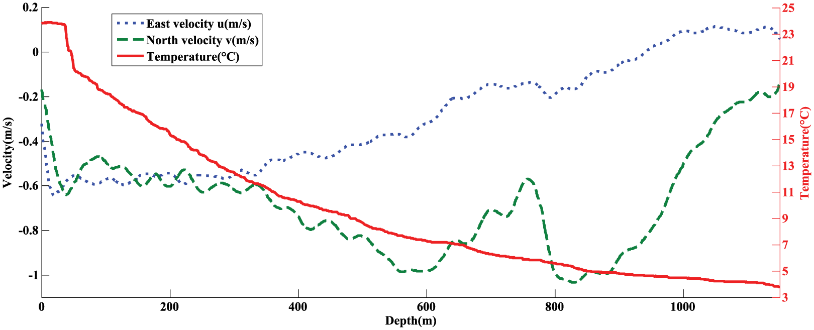
XCP Ocean current velocity and temperature information (N 21°59.42′, E 118°10.31′, 11 March 2010, 15:16)
From the temperature data in Figure 6 , it can be seen that the temperature of the seawater from sea level to 37 m BSL was stable, ranging from 23.9 to 23.7 °C; from 37 to 65 m BSL, the temperature quickly dropped from 23.7 °C to a level below 20 °C at an average rate of 1.3 °C per 10 m; from 65 to 500 m BSL, the temperature dropped from 19.82 to 8.69 °C at an average rate of 2.56 °C per 100 m; and the temperature at 1151 m BSL dropped to 3.7 °C.
The data shown in Figures 6 and 7 were collected from a place at 44.3° east by south of Shantou, Guangdong Province, approximately 215 km away from Shantou, Guangdong Province. Figure 7 shows the ocean current velocity data measured by an acoustic Doppler current profiler (ADCP) for comparison with Figure 6 . The ADCP used is an OS-75K ADCP supplied by RDI, with a maximum profiling depth of 700 m. A comparison between Figures 6 and 7 shows that the ocean current velocity measured by XCP was generally consistent with that measured by ADCP. From 16 to 600 m BSL, the velocity of the eastward ocean current gradually changed from −0.6 to −0.1 m/s, and the velocity of the northward ocean current gradually changed from −0.5 to −0.96 m/s. The top-layer ocean current ran southwestward in a direction approximately parallel to the coastal line in Guangdong Province, China.
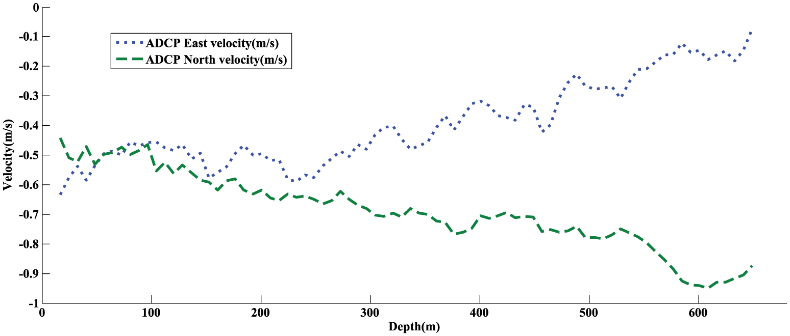
ADCP Ocean current velocity information (N 21°59.42′, E 118°10.31′, 11 March 2010, 15:27)
VI. Conclusion
The successful development of the XCP for measuring ocean current–induced electric field ensured smooth XCP-based marine investigations. In the development study, technical exploration was performed from the following aspects:
Rapid measurement of weak ocean current electric field signals in the nanovolt range under high background noise was achieved using AM modulation. During the course of rotary descent of the XCP probe, the probe modulated the ocean current electric field signals into narrow-band, single-frequency signals using AM modulation, thereby shifting the frequency of effective signals to the ultra-low-noise frequency band.
Front-end weak signal processing circuits for the XCP probe were designed. The front-end weak signal processing circuits for the XCP probe filtered and extracted weak ocean current electric field signals and compensated the in-phase component of the ocean current electric field, which overcomes the strong interference to the induced electric field due to the descent of the XCP probe to a certain extent.
By applying the SOPC technology to the XCP probe, various functions, such as digitalization of the sea current–induced electric field signals, control of the A/D conversion chip for temperature measurements, and data transmission, can be achieved using a single chip. The design of the circuit hardware is largely simplified, and flexibility of the design is improved.
Dynamic data transmission technology using an enameled wire with a diameter of 0.1 mm and a length of 2 km was developed. In a complicated marine environment, an enameled wire with a diameter of 0.1 mm and a length of 2 km with dynamic unreeling feature was used to transmit digital signals at a baud rate up to 4800 bps for the first time. LVDS transmitter was used as the physical layer transmitter for the XCP probe, thereby simplifying the physical hardware of the transmission unit. Meanwhile, for the XCP float unit, the data extraction circuit of the hardware was designed to filter out interference, thereby recovering the ocean current electric field and temperature data transmitted by the transmission unit.
The XCP ocean current data processing mode was investigated based on In, Qn, and Bn of the ocean current signals and the compass coil signals collected by the XCP probe, and the eastward component VEr and the northward component VNr of the relative velocity of the ocean current were calculated.
Footnotes
Funding
This work was supported by the Natural Science Foundation of China (No. 41574131), the National “863” Program of China (No. 2006AA09A304), the National Major Scientific Research Equipment Research Projects of China (No. ZDYZ2012-1-05-01), and the Fundamental Research Funds for the Central Universities of China (No. 2652015213).