
Abstract
This paper addresses accepted practice for the earthing of control systems in a variety of environments and is intended to give control and instrument technicians and engineers a basic understanding of the power supply earthing systems to which their equipment is connected. The general requirements for earthing in hazardous areas are also discussed.
I. Introduction
Tech Talk is a series of papers designed as a ‘pull out’ reference library. The aim is to disseminate knowledge of both the fundamentals of measurement and control and their practical application.
Design safety regulations exist in most parts of the world to prevent danger to life from electric shock due to contact with exposed metalwork concurrent with a fault condition. In the United Kingdom, these regulations are comprehensively detailed in Standard BS 7671:2008 – Wiring Regulations 17th Edition. 1 Although these regulations are not statutory, they are nevertheless regarded by the Health and Safety Executive as requirements likely to achieve conformity with relevant parts of the Electricity at Work Regulations 1989.
NFPA 70: National Electrical Code (NEC), 2014 Edition is appropriate for North America.
In England, Scotland and Wales, the Wiring Regulations assume that the electricity supply is in accordance with the Electricity Safety and Continuity Regulations 2002 2 and that there is a permanent connection from supply neutral to earth. This may not always be the case in other locations.
This paper addresses accepted practice for the earthing of control systems in a variety of environments and is intended to give control and instrument (C&I) technicians and engineers a basic understanding of the power supply earthing systems to which their equipment is connected. The general requirements for earthing in hazardous areas are also discussed. The paper is not intended as a comprehensive work on electrical earthing and related technologies.
II. Definitions
A. Nominal system voltages
Extra low voltage
An extra low voltage (ELV) circuit is one in which the electrical conductor potential does not exceed either 50 V rms, whether between conductors or to earth for AC, or ripple-free 120 V for DC under dry conditions. Lower numbers apply in wet conditions, or when large areas of metalwork are exposed to human contact.
Low voltage
A low-voltage (LV) circuit is defined as having a voltage exceeding ELV but not exceeding 1000 V AC or 1500 V DC between the conductors or 600 V AC or 900 V DC between the conductors and earth.
High voltage
A high-voltage (HV) circuit is defined as having a voltage in excess of LV.
B. Earthing
The provision of an engineered low impedance return path to the power supply transformer, such that fault currents occurring as a result of earth leakage can be automatically detected and the source of power quickly disconnected.
C. Bonding
The interconnection, using low resistance components of the conductive parts of plant and equipment, so as to provide an earth return path and ensure that adjacent components are always at the same potential.
III. Protection against Electric Shock
A. General requirements
BS 7671:2008 1 lists and describes the following protection methods:
The use of ELV circuitry (separated (or safety) extra low voltage (SELV), protected extra low voltage (PELV) and functional extra low voltage (FELV));
Automatic disconnection of supply (ADS).
Other forms of protection from electric shock which fall outside the scope of this paper are as follows:
Double or reinforced insulation;
Electrical separation of the supply to one item of current-using equipment.
This paper is mainly concerned with the earthing of ELV systems. However, those engineers concerned with the design and maintenance of such systems need to be aware of the methods of protection applied to LV supplied apparatus such as power supply transformers and electrical power distribution equipment forming an integral part of control system cabinets and other plant-mounted instrumentation equipment.
B. ELV – SELV, PELV and FELV supplies
ELV circuits may be categorised as SELV or PELV. The two systems are almost identical in that both require the same voltage limitation and the requirement of adequate electrical separation from higher voltages, either by insulation or physical methods. They also both require the use of a safety isolating transformer complying with BS EN 61558-2-6. However, they differ in that only the PELV system requires that one leg of the isolating transformer be connected to earth. PELV and SELV circuits are shown in Figure 1 .
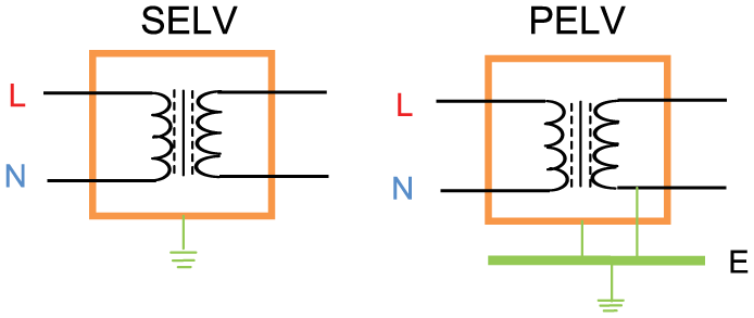
SELV and PELV power supply circuits
FELV is a term which covers other ELV circuits that do not meet the requirements for a SELV or PELV circuit as the ELV part of the circuit may not be adequately protected from accidental contact with higher voltages existing in other parts of the circuit. Thus, the protection requirements for the higher voltage part have to be applied to the entire circuit. Further discussion has thus been limited to SELV and PELV circuits.
One problem with a PELV system is that faults elsewhere in the installation may induce voltages on the entire system via its protective earth conductor.
The advantage of an SELV circuit is that there is no earth return path which might occur via the human body. A disadvantage is that an over-current protection device must be installed in each leg of each ELV circuit and sub-circuit.
C. Automatic disconnection in the event of a fault (ADS)
ADS is the most widely used form of protection against electric shock. It is appropriate where basic protection consists of measures such as the insulation of live parts by barriers or enclosures and fault protection exist in the form of earthing, equipotential bonding and automatic supply disconnection in the event of an earth leakage fault.
ADS fault protection for circuits operating at a voltage greater than ELV is achieved when the circuit-protective device operates within a defined time period for a given supply system. This depends on the circuit design parameters, which topic is not covered by this paper.
The earth loop impedance of all LV electrical distribution sub-circuits (from the protective device via the earthed equipment, returning through the earth path to the supply transformer earthed neutral connection) must be low enough to ensure that any protective device – fuse or residual current detector (RCD) will operate in the event of an earth leakage fault. Thus, protective earthing is designed to ensure that the circuit-protective device will disconnect the supply and so limit the rise in potential, above earth potential, of any exposed conductive parts for the duration of the fault.
IV. TN-S and TT Power Supply System’s Earthing
These are the two power supply earthing systems commonly found in the United Kingdom. 3 Their acronyms are derived from the following:
T = Earth (from the French word Terre);
N = Neutral;
S = Separate.
A. TN-S system earthing
As shown in Figure 2 , this system has the neutral of the source of energy connected to earth at one point only. For a three-phase system, this is normally the star point of the grid transformer’s secondary windings. The consumer’s earthing terminal is usually connected to the metallic sheath or armour of the power supply distributor’s service cable.
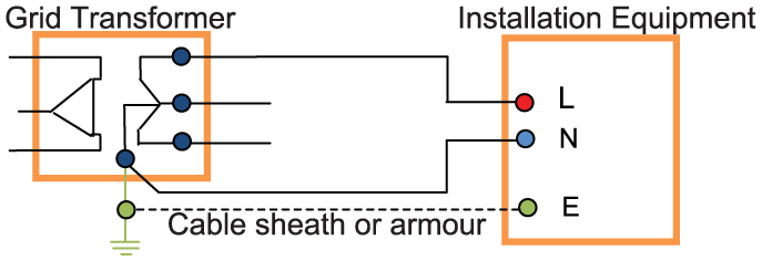
TN-S system circuit diagram
B. TT system earthing
Figure 3 shows a typical TT system of earthing.
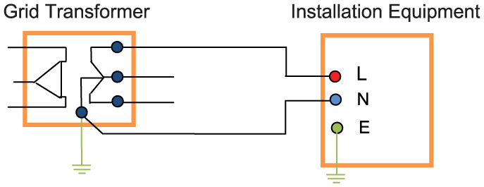
TT system circuit diagram
This has the neutral of the source of energy connected as for TN-S, but no facility is provided by the distributor for the consumer’s earthing. This is a typical situation where the power supply is connected via overhead line conductors. With a TT system, the consumer must provide their own connection to earth, that is, by installing a suitable earth electrode or connection to underground structural metalwork local to the installation.
V. Earthing Arrangements and Protective Conductors
Guidance on the selection and installation of earth electrodes and conductors is given in BS 7671:2008. 1 Further information can be obtained from BS 7430:1998 ‘Code of Practice for Earthing’. 4 A soil resistivity test of the ground is the main factor in the determination of the type and extent of earth electrode/s required. Electrodes should only be driven into previously undisturbed ground.
Other systems which may require connecting to a common earthing point are as follows:
Water installation pipes;
Gas installation pipes;
Other installation pipe work and ducting;
Central heating and air-conditioning services;
Exposed metal structural parts of a building.
The C&I designer is not immune from these regulations which require all exposed metalwork on equipment operating above ELV to be earthed.
VI. Equipotential Bonding
There is a risk from electric shock which may arise should an earth leakage fault create a potential difference between adjacent exposed conductive components. To minimise this risk, all extraneous conductive components must be bonded together and connected to the system’s general earth. Effective bonding provides an alternative earth leakage return path via a plant’s structure. This complements the electrical safety earthing system. Thus, even if the system’s main earth connection is lost, touching adjacent metal components should not give rise to a danger from electric shock. The general requirements for UK systems are detailed in BS7671. 1
For TN-S and TT systems, equipotential bonding is not intended to carry any earth fault current and therefore a separate adequately sized earth continuity conductor path must be installed.
Examples of items required to be equipotential bonded are as follows:
Control cabinets;
Cable gland plates;
Cable support systems;
Process pipe work and vessels;
Air conditioning ducts;
Concrete reinforcement;
Structural steelwork, steel walkways and handrails.
VII. Lightning Protection
Structures (e.g. buildings and plants) need to be protected from the effects of lightning strikes by the installation of an effective means of protection specifically designed for the particular structure. The steel structures of process plant are often earthed using multiple electrodes and also using the mass of reinforced concrete forming the foundations. In the latter case, the steel structure is bonded to the reinforcement at strategic points via removable test links.
There is also a requirement (statutory in the United Kingdom) to construct electrical equipment or protect it such that it can withstand the effects of adverse conditions including lightning strikes. The protection for a structure will generally also protect equipment installed within it but additional protection may be required especially where electrical links exist between separate buildings.
Surge arrestors may be installed to protect vulnerable electrical equipment in power transmission and distribution systems from lightning-induced voltage spikes caused by a nearby lightning strike or by distribution circuit switching. Consumer equipment such as computer-based systems may additionally be protected by surge protectors. Both types of device work by bypassing the voltage transient spike to earth, rather than it passing through the connected equipment.
When instrumentation and other electronic equipment are located outdoors, consideration should be given to methods of protection from lightning strike, where such an event may cause severe control system damage via interconnected cables. Metallic enclosures forming a Faraday cage which is locally earthed is one form of protection.
BS EN/IEC62305 Standard for Lightning Protection September 2006 5 is the applicable standard for the United Kingdom and Europe. In North America, it is NFPA – 780, Standard for Lightning Protection.
VIII. Control Systems ‘Clean’ Earthing
With any AC power distribution network, there will always be some leakage current to earth. This is made worse on large systems by the multiplicity of sub-circuits involved, each circuit leakage being too small to operate a protective device but contributing to the sum of the earth leakage current returning to the supply transformer. The electrical safety earth may also be subject to switching spikes and noise from inverters. Thus, even for an earth electrode having earth loop impedance within the limits of the Standard used, the earth impedance multiplied by the total leakage current will result in an AC three-phase ripple standing voltage and other ‘noise’ at various points around the safety earth busbar and interconnecting earth conductor network.
The ‘body of earth’ is often used in instrumentation and associated computing systems as a 0 V reference for signals. Noise, even if only in the order of microvolts (in the form of AC or DC signals) on the 0 V reference, may lead to unexpected results affecting control signals, including the failure of the electronics.
The term ‘clean earth’ is often used in connection with control systems, but what does it mean? A definition is: ‘A low impedance earth point with negligible chance of conducted noise either already present or likely to be created when bonded to an electrical circuit’. In practice, a single clean earth cable is connected at one point only to the general earth, this being as close as practical to the general earth electrode connection. This is necessary in order that the current return paths do not share a common path with the main electrical system currents. The use of a separate clean earth electrode should be avoided as it may result in increased system susceptibility to electromagnetic coupling (EMC) problems.
On large systems, ELV supplies to transmitters, signalling processing equipment, receiving instruments and analogue to digital converters associated with control systems may be derived from several separate AC to DC power supply units. To avoid unacceptable signal errors, care must be taken to ensure that the 0 V reference node (within the allowable uncertainty for the measurement system) is just that, and not at a slightly higher voltage caused by circulating currents between the various instrument and control system power supply voltage sources via their individual reference earth connections. 0 V earth connections must be individually wired and not ‘daisy chained’ to a reference (clean) earth busbar, which is itself insulated from the electrical safety earth.
The system designer should ensure that in order to avoid contamination of the clean earth, only the ELV 0 V DC power supplies, cable screens and cable drain wires should be connected to it. Cable armouring and any electrical equipment safety earth connections should be connected to the power supply safety earth point. In the United Kingdom, a ‘clean’ earth should be labelled as such using the IEC 60417-5019 symbol.
IX. Intrinsic Safety Systems Earthing
The most likely source of abnormal voltages invading intrinsic safety (IS) circuits is within the safe area.6,7 IS circuit protection modules are generally equipped with a busbar (see Figure 4 ), which when connected to the neutral star point of the grid transformer via a low impedance earth path ensures that any significant fault current is kept outside of the hazardous area. The generally accepted earth loop impedance for an IS earth is 1 ohm; however, 0.1 ohm is preferable and often achievable.
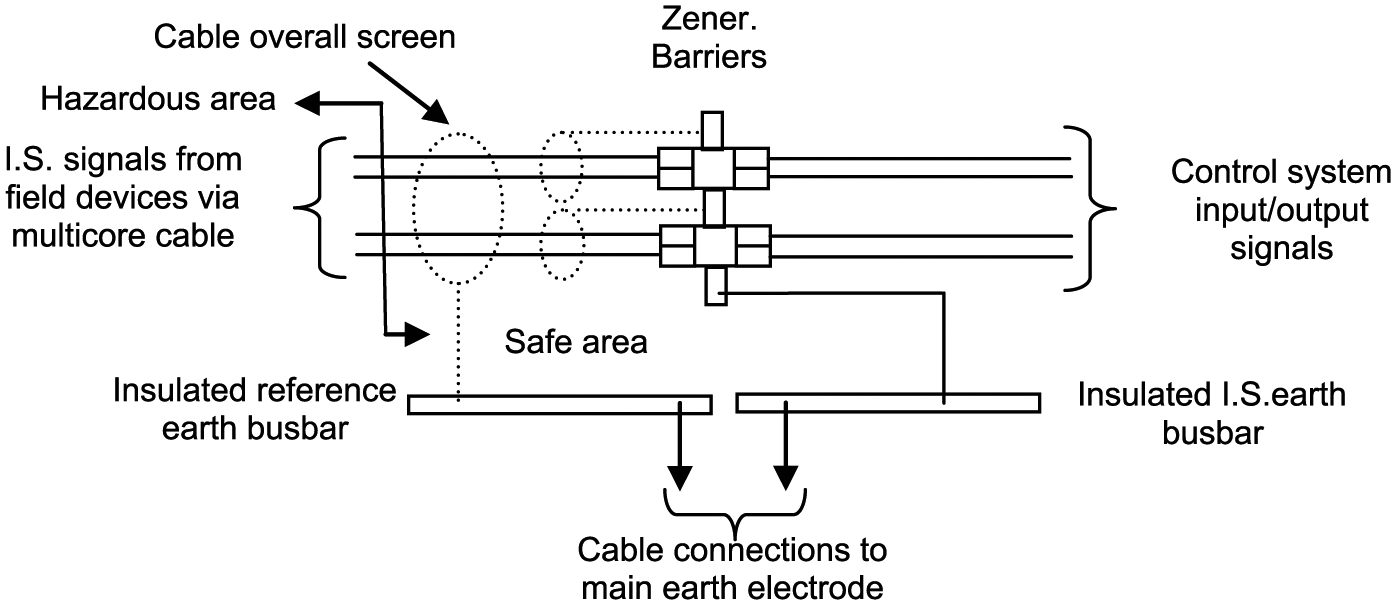
IS earthing circuit diagram
Current flowing through the IS earth bonding conductor generates a potential difference between the IS earth point at the barriers and the supply transformer neutral star point. The metallic cases of instruments in the hazardous area are bonded to the transformer neutral star point, and the instrument internal circuits are connected to the barrier busbar. The potential difference between the IS earth point at the barriers and the transformer neutral star point is thus transferred to the hazardous area. Although normally safe, as the internal circuits are isolated from the instrument housing, this potential difference should be minimised so that in the event of a local insulation failure, the IS system safety integrity is preserved. Thus, a fundamental requirement concerning the earthing of IS zener barriers is that the IS earth, control signal 0 V reference earth and the electrical power earth must be independent of each other and only meet at the ‘body of earth’ (see section XII). This philosophy accords with industry best practice and recommendations for the earthing of electronic and computer-based systems.
ELV control signal cables are often electromagnetically screened to increase protection against magnetic coupling (cross talk) from nearby power cables. The screen generates a current which neutralises the source magnetic field. Theoretically, there is no need to earth this screen; however, it is common practice to bond it to a clean earth or IS earth in the case of hazardous area systems as such bonding provides capacitive coupling screening and also provides a means of calculating the screen’s electrostatic potential.
A comprehensive treatment of earthing requirements for hazardous areas can be found in Towle 6 and Coles. 7
X. Earthing Arrangements for Instruments’ Field Cable Screens
Screened cables are commonly used to minimise adverse effects to electronic equipment from capacitive coupling (cross talk) between cables, particularly for analogue signals from plant instruments through any intermediate marshalling box up to the control system input/output marshalling cubicle. The use of twisted pair cables or metallic conduit provides additional protection from electromagnetic radiation.
Unless otherwise advised by an equipment manufacturer, cable screens should only be earthed at one point. Earthing via the screen drain wire is commonly carried out at the control system input/output marshalling cubicle with the screen at the field device being left un-earthed and insulated. This is to prevent any plant structure earth return current that may arise if the screen was earthed at both ends. In this event, the earth loop current becomes a noise source affecting the signal conductors. Figure 5 shows a typical wiring arrangement.

Interconnected cable screens
XI. Electrostatic Earthing
A. General requirements
Many industrial processes which move fluids and powders within pipes generate static electricity. In hazardous areas, this poses an ignition risk and a risk of shock to personnel. Although effective containment of explosive fluids and dust is the first layer of safety protection, the second layer is the elimination of potential ignition sources. In the United Kingdom, this is a legal requirement under the Dangerous Substance and Explosive Atmosphere Regulations (DSEAR). These regulations require that electrostatic hazards be assessed alongside other potential sources of ignition such as electrical and mechanical process equipment.
While it is not always possible to prevent the generation of static electricity, the technique of earthing can be used to safely discharge it and eliminate these risks. BS 5958 – Code of Practice for the Control of Undesirable Static Electricity (1991) 8 contains detailed information on the hazards and the precautions required to prevent unwanted consequences relating to static electricity.
The most common source of danger from static electricity is the retention of charge on a single item of plant or equipment (a conductor) because all of the stored energy can be released in a single spark to earth or to another conductor. The accepted method of avoiding this hazard is to interconnect all of the conductors to each other and to earth via conducting paths with sufficiently low resistance to permit the dissipation of any static charge.
The accepted rate of static charge generation in industrial processes is such that a resistance to earth up to 106 ohm will ensure safe dissipation of static.
Within metallic plant and equipment, much lower resistances to earth can be achieved and readily measured. Here, it is usual to use a figure of 10 ohms for the maximum resistance to earth. Where such equipment is bolted to steel supporting structures, the bolting will normally ensure adequate earth bonding without the need for separate earth conductors.
Thus, the requirements for protection against static electricity may be met by a common earthing system to which all structures and items of process equipment are electrically connected.
Where conductive non-metallic and anti-static materials are used, the 10 ohm target is inappropriate and the 106 ohm value may be used.
Note that earthing of plant/equipment does not necessarily eliminate static charge within the fluid/product itself.
B. Bonding of metal pipes in hazardous areas
Flange joints on plant equipment and pipe work handling flammable materials should be bonded across.
Pipe work carrying non-flammable/non-conducting liquids in areas where flammable materials are handled should be subject to precautions as for flammable liquids.
Where flexible/non-metallic pipe connections or in-line non-metallic devices such as flow meters are involved, the end flanges of these devices should be effectively bridged by an earth conductor.
XII. Supply Transformer Star Point Earthing
Multiple electrode connections to earth will have varying earth loop impedance values due to factors such as the length of earth bonding cable and local soil resistivity. This situation can lead to problems with electronic equipment as the various earths will have potential differences between them. There is also a risk due to transient surge damage. The answer is found in the commonly accepted practice of connecting all ‘earthing’ systems to a single earth electrode connection point. This electrode, whatever its physical configuration, then provides a single earth route to the grid transformer neutral star point. Figure 6 shows a typical star point earthing circuit arrangement for an industrial installation. The connection to the earth electrode from each earthing sub-circuit’s ‘collecting’ busbar should be kept as short as possible and the cable sized so as to add negligible impedance to the earth loop. Note: An alternative method of connecting the IS Earth busbar to the Safety Earth is by connection via the 0 V earth bar.
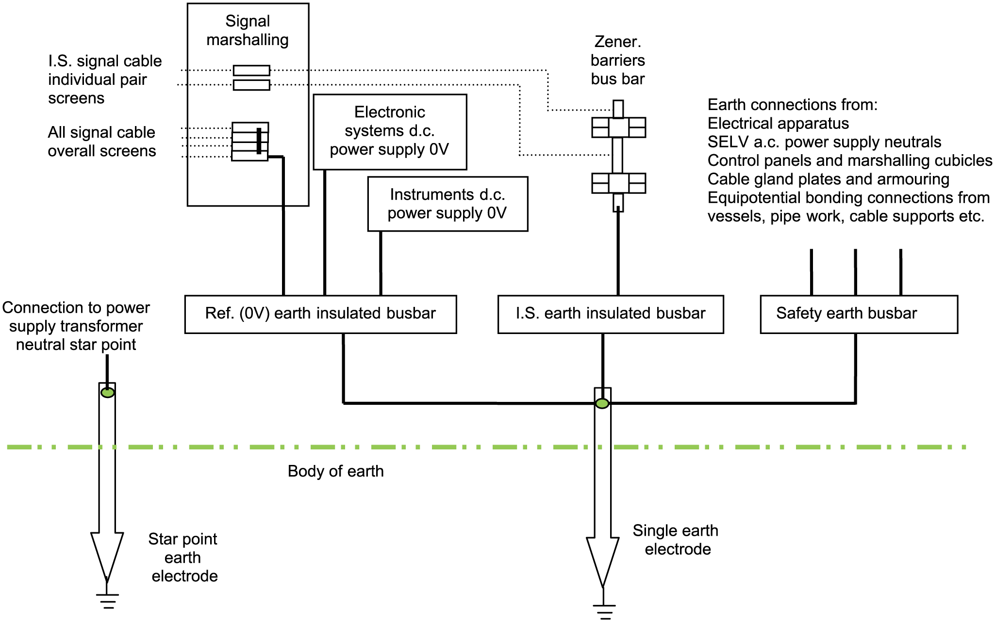
Typical star point earthing circuit (TT system)
Footnotes
Funding
The author(s) received no financial support for the research, authorship and/or publication of this article.