
Abstract
The Sellafield site, formerly known as Windscale and Calder Works, is a large nuclear plant sited in West Cumbria, in the North West of England. The Sellafield site is probably the most complex nuclear facility in the world, with safety systems to match. Many of the safety systems have been ‘back-fitted’ onto decades-old plant as safety cases have been modernised; however, due to the original design, many of these systems cannot be fully end-to-end proof tested. It is for this reason, Sellafield Ltd has developed their own risk-based process of how to assure the probability of failure on demand of a safety system when one or more of the components of the system cannot (throughout this paper where it is stated that the proof test ‘cannot be carried out’ it means it is undesirable for safety, practicality or business reasons) be fully or actively tested. Sellafield Ltd are leading the way in the proof testing of legacy plant throughout the nuclear and chemical industries in the United Kingdom; these arrangements, as described below, are considered (by Sellafield Ltd) as best practices for assuring the probability of failure on demand of Safety Instrumented System in legacy plants.
I. Introduction
A. What is a Safety Instrumented System
A safety system is installed to reduce risk and may be passive or active in nature. Functional Safety is the active part of the safety system; that is, Functional Safety is the part of the safety system which depends on the correct functioning of the Safety Instrumented System (SIS).
A SIS includes all components and subsystems necessary to carry out the safety function from sensor(s) to final element(s). Functional Safety addresses SISs regardless of the technology used, for example,
Control, electrical and instrument (CE&I) systems;
Fire detection systems;
Pressure relief valves;
Electrical overloads;
Mechanical interlocks;
Pneumatic valves.
B. What is a proof test
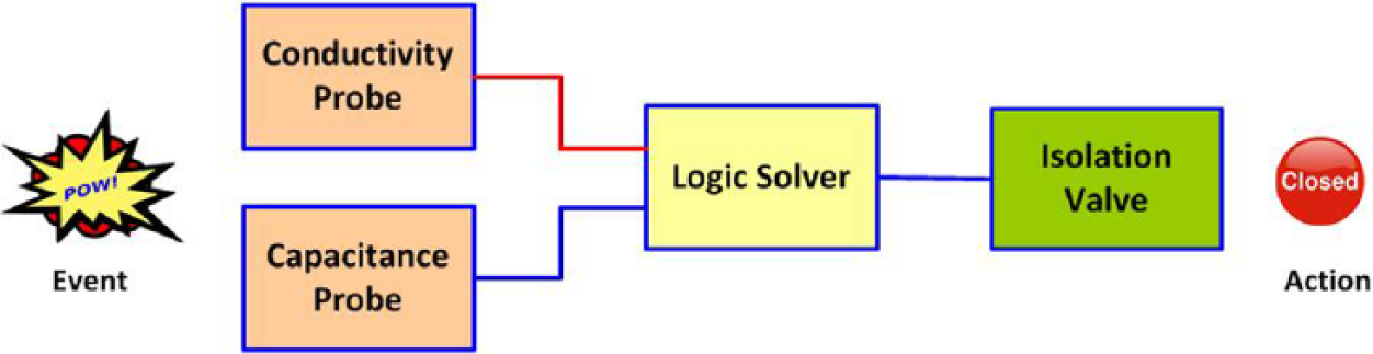
A proof test is designed to expose any ‘reasonably foreseeable unrevealed dangerous failures’ of the safety function in an SIS. An ‘end-to-end’ test, as the name suggests, is a test designed to test from ‘the sensor through the logic solver to the final element’. Figure 1 shows the three main elements of a safety system.

The three components of a safety system
However, to complicate matters, an ‘end-to-end’ test is not necessarily a proof test, for example, if there are multiple sensors, multiple logic solver paths or multiple terminators in the SIS (which is the case in many complex systems), it may not be obvious which elements have provided the safety function; Figure 2 gives an example of a safety system with multiple sensors.
Safety system with multiple primary elements (level probes)
If an action was initiated at the sensor end and the reaction noted at the final element, how do we know which sensor detected the abnormal condition and/or which terminator took the mitigating action?
A simple example of this is a bund in a chemical plant where high liquid level is detected and alarmed by two level sensors using diverse technologies to eliminate common mode failure. This could mean that a capacitance probe and a conductivity probe are designed to detect the level of liquor in the bund and trip a relay to close an inlet valve.
If the proof test consists of a known amount of liquor being poured into the sump and the valve closes, that is a successful end-to-end test; however, it is not necessarily a proof test as it may not be known whether both primary elements are operational.
C. Define the safety function
The definition of the safety function must be clear, accurate and concise, with enough details to make it unambiguous. The use of unnecessary jargon, acronyms or technical terms is to be avoided.
Plants designed and built pre IEC 61508 1 may not have been designed with testing in mind, and the concept of full end-to-end proof testing may not have been considered. This leaves the industry with the challenge of proving our SIS can provide the Safety Function claimed in the Safety Case.
As will be shown, reasonable confidence that the probability of failure on demand (PFD) claimed in the safety case can be underpinned and may be demonstrated by taking a risk-based pragmatic approach.
D. Why do we proof test
There are two main reasons for carrying out proof testing:
To demonstrate the satisfactory performance of a safety function, that is, safety case driven;
As a requirement after intrusive maintenance to confirm the integrity of the safety function – intrusive maintenance is defined as ‘maintenance that has the ability to induce failures’. For example, If cables or pipework are connected or disconnected, there is a possibility that the re-connections may be made incorrectly; If alarm settings or other parameters are set or reset, these changes may take the configuration outside the required Safety Envelope; Changes to configuration, for example, valve positions (e.g. equalising and isolating of instrument pneumatic systems) and switches (e.g. duty/standby selector switches, ‘dual in-line (DIL)’ switches on circuit boards).
Scope of the proof test
The scope of the proof test must address the statement ‘Proof testing should be designed to expose any reasonably foreseeable unrevealed fail-to-danger fault conditions in all components including process sensors, logic solvers and final elements’. 2
The term reasonably foreseeable can be taken to mean an incident or accident which is thought to be credible, although the term does not appear to be defined exactly in legislation.
The proof test coverage follows a hierarchical structure: at the top of the hierarchy is the full end-to-end proof test, at the bottom is the least favoured fully simulated test and in between, permuta-tions of simulation and actual testing.
It must be stressed that the prime aim in the design of a proof test is to test the entire safety function but without placing plant or personnel in danger.
II. What Is the Issue with Legacy Plants?
Process protection functions designed and built pre-1999 may have had little or no test facilities or functions built into them; this can make the complete testing of SIS undesirable for safety, practicality or business reasons, for example, compliance with the principle of risk reduction to As Low As Reasonably Practicable (ALARP) would not be achieved for a maintainer needing to enter a tank containing sulphuric acid fumes in order to test a level probe using a bucket of acid. Likewise, it would not be practical to fill the tank with acid just to test the probe and then to dispose of the acid; nor would that make business or environmental sense.
A safety system may comprise a single device or many instrument loops each contributing to the overall Risk Reduction Factor of the Safety Instrumented Function (SIF). The PFD claim for each SIF will assume that it is adequately maintained and proof tested at a pre-determined interval to achieve the PFD. It will also be assumed that the proof test is ‘100% coverage’, that is, the proof test will reveal all reasonably foreseeable unrevealed dangerous failures.
III. Design of the Proof Test Instruction for the SIS in Legacy Plants
Even in legacy plants there will be many applications where it is possible to fully test the SIS; however, just because it is possible does not mean it is justifiable to carry out a full test.
It is acknowledged that it is good practice to fully test, as far as is reasonably practicable, all SISs, and the goal when designing a proof test is always to demonstrate the functionality from end to end.
It is very important to carefully define the safety function so that any failure can be easily identified. Any alarm or trip points, such as the fluid level in a tank, must be defined in engineering units with tolerances also quoted in engineering units, for example, a high-level trip in a tank defined as 1500 ± 75 mm.
Once the safety function is understood, a procedure can be designed to fully test it, bearing in mind the ‘definition’ above.
This paper sets out a proof testing methodology designed to align with the ‘Guiding Principles’ referred to in ‘Principles for proof testing of SISs in the chemical industry’. 3 This is recognised as industry good practice.
A. Is it safe, practical and economically sound to carry out the proof test?
When designing a proof test procedure, apart from the technical attributes of the test, there are three key questions to ask.
Is it safe?
Assuming that a proof test has been designed which will fully test the safety function, consider the following question: ‘Can this test itself be carried out safely?’
Assess whether it is safe to perform an end-to-end proof test; the assessment shall include (as a minimum) consideration of whether the test
Could put any person at risk of hurt or harm;
Could put the plant into an unsafe or hazardous state.
For these and other safety reasons, it is not always possible or desirable to carry out an end-to-end proof test. The proof test shall not be designed such that it creates the hazardous condition for which the safety function is there to prevent. Such a test may fail, resulting in an accident, the creation of waste, the exposure of people to risk and so on.
An example of an unsafe proof test would be driving a car into a wall at 30 mile/h to test the air bag.
Good practice. The proof test of a safety system should reflect real operating conditions as accurately as possible. If reasonably practicable, the safety system should be initiated by manipulation of the process variable without driving the process into the hazardous (demand) condition. 4
Is it practical?
Assess whether it is practical to perform an end-to-end proof test; consider a risk/benefit analysis:
What will be the environmental impact?
Will the safety system reliability be proved any better because of the test?
It may be safe to add 30 m3 of liquor into a tank to test the level instrumentation, but is it practical? How easy is it to add the liquor? How easy is it to dispose of the liquor?
An example of a test which may not be practical would be for a user to test a car’s anti-lock braking system (ABS) by slamming the brakes on at 70 mile/h; however, the manufacturer may do this under controlled conditions.
Good practice. Where process variables cannot be safely or reasonably practicably be manipulated, sufficient confidence in the correct operation of sensors should be gained by other means, such as comparison with other measurements. 5
Is the sacrifice proportionate to the benefit?
Assess whether an end-to-end proof test, at the given periodicity, adds safety benefits proportionate to the sacrifice; for example, what extra safety benefit will carrying out the test annually give us over a four yearly test; that is, is the cost of an annual test disproportionate to the increase in PFD?
Even if an end-to-end test has been declared as both safe and practical, it may not be the best business strategy; for example, it may not be environmentally sound to fill a tank or a sump with 30 m3 of liquor to test a high-level alarm every 12 months, or the test may be prohibitively expensive to carry out.
Some complex proof tests can take many hours or even days to set up, carry out and reset the plant for operation.
What is the best test procedure that is safe, practical and proportionate?
If the response to any of the previous three questions is no, then a new test procedure should be designed which will test the SIF as thoroughly as possible while enabling the designer of the proof test procedure to say ‘Yes’ to each of the three questions above.
In theory, for any new plant designed to the principles in BS EN 61508, 1 the designer of the proof test procedure should not be able to say ‘no’ to the three questions above.
This paper will not give the solution as there are far too many permutations to address, as well as differing tolerable risk levels in different industries.
B. Assess the best test procedure for gaps
Assess whether the best test procedure designed above will satisfy the definition of a proof test; that is, a proof test is designed to expose any ‘reasonably foreseeable unrevealed dangerous failures’ of the SIF in a SIS.
Identify any gaps between the best test procedure and the requirements of the definition. Gaps may include test coverage or test periodicity of the system.
C. Introducing four different types of SIS test coverage
There are four ‘levels’ of test coverage for instrument loops that make up the SIS.
SIS loops that can be fully end-to-end proof tested
Loops that can be fully end-to-end proof tested (100% coverage) in a safe, easy, environmentally friendly and economic manner. Experience shows that in legacy plants, these probably only make up between 20% and 40% of all SIS instrument loops.
The PFD of the SIS will be underpinned by this test.
SIS loops that cannot be fully end-to-end proof tested at the desired frequency
Loops that cannot be fully end-to-end proof tested in a safe, easy, environmentally friendly and economic manner at the desired frequency.
A possible solution. A partial proof test on the SIS loop is carried out and this partial proof test would be supplemented by a full end-to-end proof test at an extended periodicity.
The PFD of the SIS could be underpinned by these tests.
SIS loops that cannot be fully end-to-end proof tested
Loops that cannot be fully end-to-end proof tested; that is, there are no safe, practical and commercially sound methods of how this can be done; however, the untested element is exercised in normal operation.
Solution. A partial proof test on the SIS loop is carried out at the periodicity required by the safety case.
The proof test would be supplemented by identifying confidence-building measures (CBMs) to provide assurance the untested element is operational.
The PFD of the SIS could be underpinned by this test when supported by the CBM.
Other SIS loops that cannot ever be fully end-to-end proof tested
Loops that cannot ever be fully end-to-end proof tested, and the element that cannot be tested, is not exercised in normal operation.
In this scenario, a revised Hazard Analysis (HAZAN) would be required; ALARP arguments, re-designation of other more appropriate measurements or re-engineering to meet a Safety Integrity Level (SIL) would all have to be deployed to build the case; that is, re-design is required.
The PFD of the SIS cannot be underpinned.
D. How to assure the PFD when a full end-to-end proof test cannot be carried out?
There are two main methods of underpinning the PFD of a system when the system cannot be fully tested:
For systems that cannot be proof tested at the required periodicity, a reduced coverage proof test followed by a full proof test on a much extended periodicity;
For systems with element(s) that cannot be tested, CBMs may be used to assure the integrity of the element(s) that cannot be tested.
IV. How Reduced Coverage Proof Testing Affects the PFD
A. Partial proof test
Figure 3 shows the effect on the system PFD of carrying out partial proof testing, and in Figure 4 , we see how the PFD is reset when a full proof test is carried out.
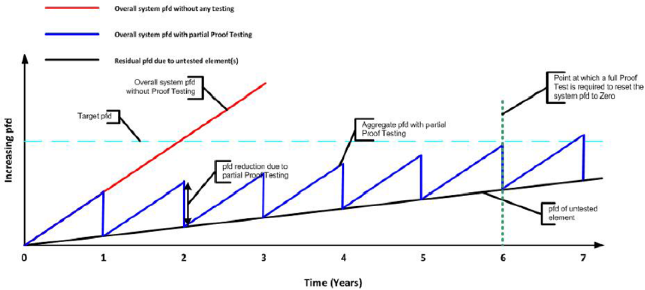
Effect of partial proof testing on the PFD
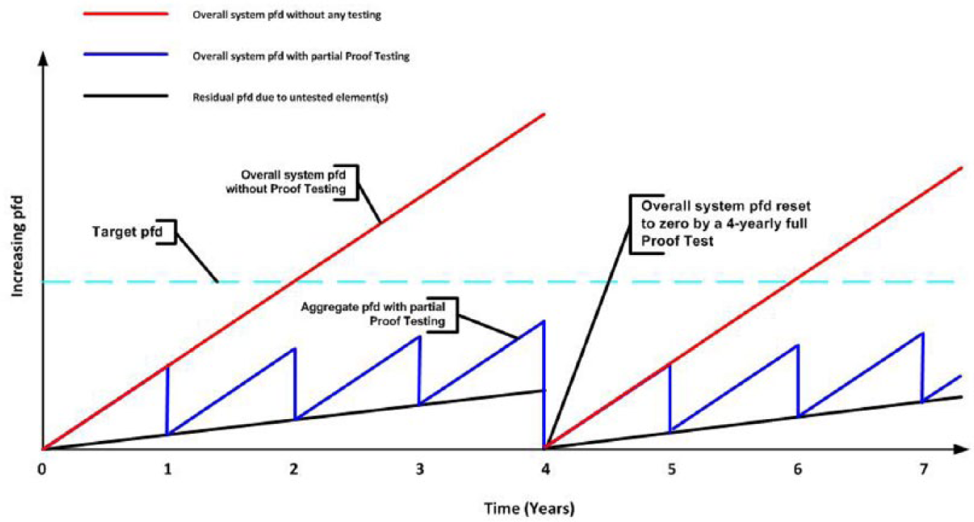
Effect a four yearly full proof test has on the aggregate PFD
The red line shows how the PFD increases with no testing; it shows that the target PFD will be exceeded after 2 years without testing.
The black line shows the increase in PFD attributed to the untested part of the safety function. This will continue to rise irrespective of the testing of the rest of the system.
The blue line shows the effect of carrying out partial proof testing on the overall system PFD. The partial proof test ‘resets’ the PFD after each successful test; however, it can only reset it to the ‘residual’ PFD attributed to the untested part(s) of the system, which itself will reach the target PFD after a number of years.
The element(s) of the system that are not tested tend to be the primary elements, for example, impulse lines and sample lines from cells and vessels. The PFD of these untested element(s) cannot be ignored as it will eventually tend to 1, and even before that point, it will affect the overall system PFD to such an extent that the partial proof test will not reduce the system PFD below the target PFD.
In Figure 3 , it can be seen that at the end of year 6, the system PFD is almost at the target PFD, and before the end of year 7, the system PFD will have exceeded the target PFD – a system failure, that is, failure of the safety function.
B. Partial proof test with extended periodicity full proof test
It can be seen in Figure 3 that the PFD of a system that is only partially proof tested will eventually exceed the maximum allowable PFD.
In many cases, where the full proof test cannot be carried out at the periodicity specified in the safety case, it may be practical for the full proof test to be carried out at an extended interval, for example, as follows:
For a tank whose level naturally increases over a period of time, the extra high-level safety function can be tested under controlled conditions. If this tank fills up regularly, the controlled test could be planned to be carried out at intervals of ‘X’ years.
The ‘Shut Down’ of a plant or process may provide an opportunity to test safety functions such as extra low temperature, pressure and flow.
Such a full proof test may result in the ability to reset the PFD to 0.
Figure 4 shows the effect a four yearly full proof test has on the aggregate PFD. The full proof test resets the whole system PFD as the whole system is tested.
C. Extended full proof test periodicity
To underpin the required PFD, if full end-to-end proof test cannot be carried out at the required periodicity, the combination of a reduced coverage test and a full test at different intervals can deliver the same probability of failure on demand.
A partial proof test should be carried out at reduced periodicity (e.g. 12 monthly to 6 monthly). The untested element should be tested on a lesser frequency. This extended periodicity proof test could be planned into a plant outage or during natural plant operations.
This principle is explained by Dearden. 6
The following extract is from Functional Safety in Practice: If a partial proof test is implemented more frequently in recognition of the partial coverage, the requirement to perform a full test to provide 100% coverage can be at extended intervals. If a full 100% proof test would be required at period T to achieve the required PFD a partial test at twice that frequency (period T/2), would mean a full 100% (Maintenance Interval) check would only be required at an extended interval if the same PFD is to be maintained.
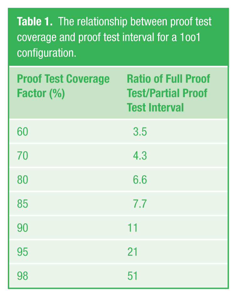
The relationship is summarised in Table 1 below.
So if a proof test with 100% coverage would be required every year (T), the same PFD could be achieved with a partial test at 90% coverage every 6 months (T/2), and a full 100% test every 11 × 0.5 = 5.5 years.
The relationship between proof test coverage and proof test interval for a 1oo1 configuration.
D. Systems where element(s) cannot be tested
There are safety systems with element(s) that cannot be tested (or it would not be reasonable to test – for various reasons). In such cases, the untested element(s) need their PFD to be ‘underpinned’ by other means; for example, if a sump level is measured using the air reaction method (the pneumercator) and it is not reasonable to test the integrity of the dip pipe, reasonable confidence that the dip pipe is serviceable may be gained by various CBMs.
What are CBMs?
The use of CBMs is a risk-based, pragmatic approach used to determine within reasonable confidence that the safety function of the SIS instrument loop is being maintained. This approach is directly in line with the Guiding Principles defined in the report in CRR 428/2002. 5
In the report, Proof Test Practices, Statement of Guiding Principles 5 states, ‘Where process variables cannot be safely or reasonably practicably be manipulated, sufficient confidence in the correct operation of sensors should be gained by other means, such as comparison with other measurements’.
How are CBMs used?
When an assessment is carried out on the coverage of the proof test and its ability to adequately exercise the safety function of the SIS, gaps may be identified.
The examples below show how CBMs can give the engineer reasonable confidence that the SIS is working correctly and that the PFD can be underpinned:
The high-level probe within a tank cannot be accessed, and it is unreasonable to add liquor to the tank;
A long thermocouple mounted within a furnace thermowell should not be withdrawn due to the possibility of not getting it back to the correct position.
There are many plant attributes that can give confidence that the untested element of the safety function is operational and would respond, to and satisfy, a demand on it.
Examples of factors that can give confidence that the untested element of the safety function would operate in the event of a demand on it are as follows:
Comparison to adjacent readings. If the measurement has local similar readings and they indicate similar results then the operation of the element can be assured.
Real demands on the safety function. There is probably no better test than a real demand on the safety function provided that the excursion from the norm has been historically logged and the reason for the excursion understood.
Before and after readings. On simple self-contained instruments, if there is a strong correlation between the plant reading taken before the test and the reading taken after the test (of the rest of the safety systems), then this may give the confidence that the primary element is operational.
Response to normal operations – trending. Historic supervisory control and data acquisition (SCADA) data can confirm that the element is responding to plant conditions, and historic readings suggest strong correlation.
Visual inspection. It may be possible to visually inspect the element to ensure that it is intact or that the sump is empty.
Operator rounds. The operator is probably one of the best aids to a maintainer, they know what their plant should be reading and routinely collect data and respond to abnormalities.
Other desktop measures are also available such as reliability figures, Failure Modes Effects Analysis (FMEA) studies and feedback from manufacturers.
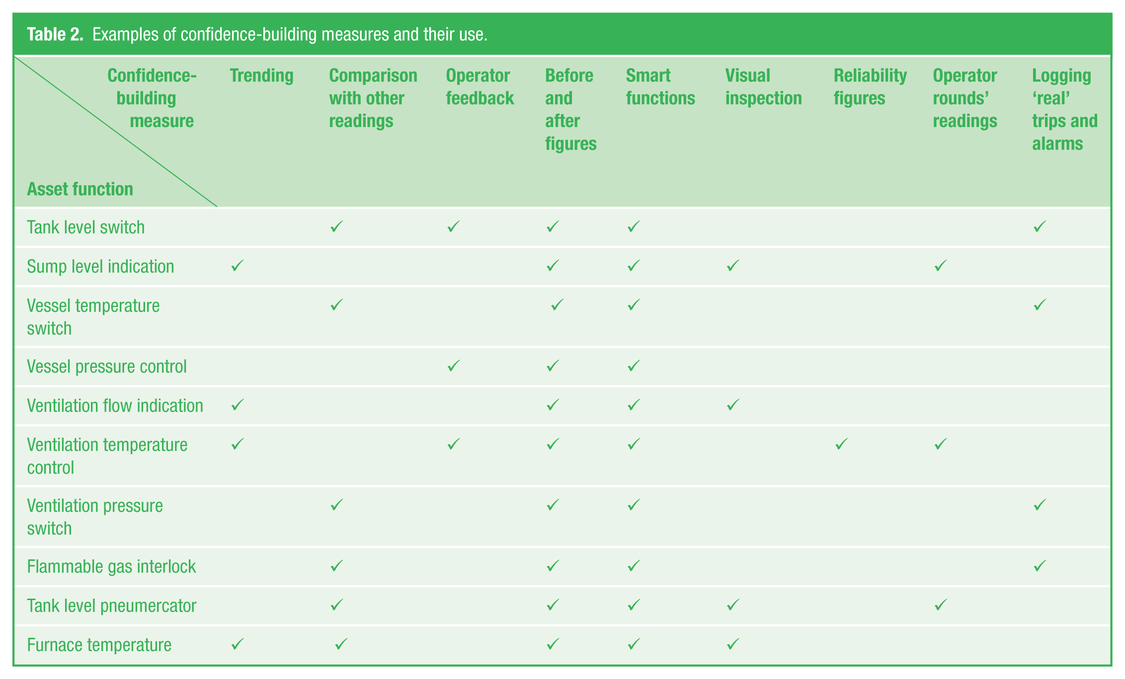
Table 2 gives further examples of CBMs and the functions they can assist in underpinning the integrity of the safety function.
Examples of confidence-building measures and their use.
How to use the CBMs
The use of CBMs should be used to underpin the activities carried out in the best test procedure that does not give 100% coverage of the ideal proof test; that is, a proof test that is designed to expose any ‘reasonably foreseeable unrevealed dangerous failures’ of the SIF in an SIS.
Footnotes
Funding
The author(s) received no financial support for the research, authorship and/or publication of this article.