
Abstract
This paper presents a real-time hydrodynamic lubricant feeding conditions monitoring system for journal bearing in tandem cold mill to avoid online burning accident. A new kind of sensor connector has been developed to perform as a measuring section applied with nondestructive testing technology. The hydrodynamic lubricant feeding conditions in the tandem cold mill have been characterized. The monitoring results show that the hydrodynamic lubricant feeding conditions have been proved to be good indicators for the safety production. This real-time hydrodynamic lubricant feeding conditions monitoring system can be used as a long-term monitoring platform and provide an early warning for the tandem cold mill’s abnormal performance.
I. Introduction
The technological innovation to have a production technology with cost competitiveness was required, and the tandem cold mill with fast speed has been developed since 1990s. 1
The hydrodynamic lubricant feeding conditions (HLFCs) of journal bearing play an important role in the safety production, and the HLFCs directly affect the production and quality of steel sheet in the tandem cold mill. Recently, under the guiding principle of energy conservation, the amount of lubricant supply for a journal bearing has been decreased with a rough estimate, while increasing the risk of sudden deterioration of lubricant conditions. 2 Accidental breakdown of the bearing would bring the whole production line to a standstill.
However, the tandem cold mill is chronically running under complex operating condition of fatigue and heavy loads, 3 the harsh environment of industrial field site makes HLFCs difficult to be monitored, owing to the persuasive data must be measured close to the hydrodynamic lubricant inlet port of the bearing. Furthermore, the complicated arrangements of sensors are not feasible in industrial applications, because the placement of sensors into the relatively low strength Babbitt metal can affect the integrity of the bearing. 4 Therefore, it seems that the harsh environment and industrial application value still make the monitoring of HLFCs a big challenge.
Historically, feeding temperatures can be used as an indicator to monitor the performance of a bearing. 4 The monitoring techniques for bearings have been discussed by Garner and Leopard, 5 including the measurement position, types of temperature sensor and methods of installation. Heshmat and Pinkus 6 studied the mixing inlet temperatures in hydrodynamic bearings as a function of a range of operating conditions for both journal and thrust bearings. Keogh and Khonsari 7 introduced a thermohydrodynamic analysis and found that mixing in the inlet groove might cause a significant influence on film entry temperature. Ma and Taylor described an experimental apparatus. The temperature distribution, power loss of a two-axial groove circular bearing and elliptical bearing were tested, as well as the flow rate was measured manually by collecting the drain oil. 8 Costa et al. 9 presented the influence of supply pressure on the performance of a journal bearing. Kucinschi and Fillon 10 studied the experimental determination of temperature distribution in a plain, steadily loaded journal bearing. Wang and Khonasari11,12 have analyzed the effects of oil inlet pressure and inlet position of axially grooved infinitely long journal bearings. Recently, the method to improve temperature monitoring of polytetrafluoroethylene (PTFE)-faced tilting pad thrust bearings has been proposed by Glavatskih13,14 according to API guidelines, which provided an oil circulation around the thermocouple tip to improve measurement sensitivity. Brito et al.15,16 carried out an experimental investigation of the influence of supply temperature and pressure on the performance of a two-axial groove hydrodynamic journal bearing. And the effects of lubricant feeding pressure and temperature on bearing performance have been analyzed. 17
In fact, the above researches have carried out a series of valuable theoretical and experimental works on these journal bearings. However, the experimental studies focused on the industrial application of hydrodynamic journal bearing reported in the literature are scarce, especially in the monitoring of HLFCs.
In this work, a method of online monitoring of HLFCs in a tandem cold mill has been proposed. A new kind of real-time hydrodynamic lubricant feeding conditions monitoring system (RHMS) for industrial scene application has been developed. The RHMS includes a novel sensor connector (SCR) and a monitor system. The monitoring parameters include hydrodynamic feeding pressure, feeding temperature and feeding flow rate. In order to validate the performance of the RHMS, back-up roll’s journal bearing at operation side of 1420 mm tandem cold mill rolling stand 4 in Baoshan Iron & Steel Co. Ltd, in the People’s Republic of China, has been selected as a monitoring object, as shown in Figure 1 .
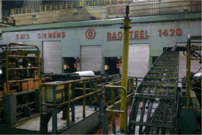
1420 mm tandem cold mill in Baoshan Iron & Steel Co. Ltd
Additionally, HLFCs of the tandem cold mill have been characterized using RHMS. Monitoring results under different rolling conditions have been discussed. The analysis focus is put on the method that how to prevent an online burning accident according to the HLFCs.
II. Traditional Method of Failure Analysis in Tandem Cold Mill
Some research works have been carried out on this issue by Wang 18 and Xing et al. 19 with traditional method, both focusing on the failure of static pressure pump. They found the corrosion cause the deterioration of the static pressure pump, and thus a corrosion preventing method was proposed. However, sudden deterioration of lubricant conditions still occurs occasionally. In order to avoid unexpected shutdown, it is necessary to develop a method to access the HLFCs online and provide an early warning for the tandem cold mill, rather than using a traditional analyzing after the accidents.
III. Description of RHMS
The configuration of the RHMS and the hydrodynamic lubrication system of tandem cold mill is shown in Figure 2 . The hydrodynamic feeding pressure loss along the path from the outlet of pumps to the inlet of the bearing, the failure of the regulator, the difference of environment temperature between pump room and mill stand, the clogging up of the oil filter and an oil leak from a loosened pipe joint 20 all can influence the accuracy of the measurement data. Therefore, in order to obtain the reliable data, the monitoring point has been selected close to the hydrodynamic lubricant inlet port of the bearing, which clearly indicates the HLFCs. A novel developed SCR works as a measuring section. The upstream port of SCR is connected to the hard tube of hydrodynamic lubrication system and the downstream port is connected with the hydraulic hose. HLFCs are measured when the hydrodynamic lubricating oil flows through the SCR.
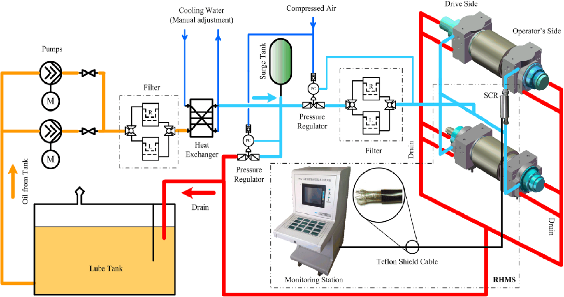
Schematic arrangement of RHMS
IV. Design and Implementation of SCR
The main design issue of SCR is that it should not affect normal production order, especially the roll change process. The dimensions of SCR are required to be compact enough subject to the pipeline distribution in the housing.
The material of protective structure of SCR is 304 stainless steel, enabling SCR to be acid resistance and corrosion resistance in severe environment. The design structure of SCR is illustrated in Figure 3 , this kind of structure ensures that it does not need to be disconnected in the process of roll change.
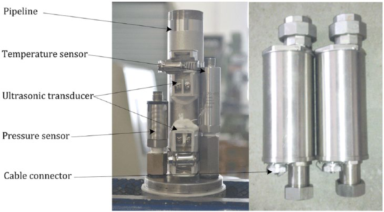
Design structure of SCR
In order to fulfill the requirements of Plug and Play, PT100 thermal resistance temperature sensor (Yuden TD04-2120-4NN) was adopted to measure the hydrodynamic feeding temperature, rather than using thermocouples. Meanwhile, current output signal (4–20 mA) is suitable for transmission over long distances in the industrial field, as well as in the consideration of having compatible instrumentation 6 for data acquisition system. The temperature sensor covers a measurement range of 0–100 °C with accuracy less than 0.5% F.S.
A pressure sensor ranging from 0 to 1 MPa (Huba Control OEM 511) has been used to measure hydrodynamic feeding pressure with measurement accuracy less than 0.3% F.S.
Hydrodynamic feeding flow rate has been measured by the ultrasonic flowmeter based on transit-time principle, which has an advantage over differential pressure flowmeter in that it is non-intrusive and without any excess pressure drop. 21 Any additional pressure drop will reduce the hydrodynamic lubricant feeding pressure of the journal bearing.
A kind of clamp-on ultrasonic contrapropagation transducer has been applied. As a general rule, a couple of piezoelectric transducers were clamped on the outside of the stainless steel pipeline aligned to the axis of the pipeline, including a sender and a receiver, which is known as the “V-mode” configuration, 22 as can be seen in Figure 4 . They send two ultrasonic pulses across the pipe and measure the transit time of each signal, the transit time and the differential time of flight are functions of the fluid velocity.
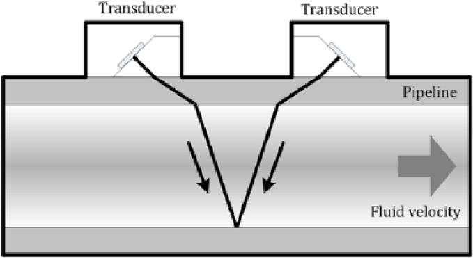
Schematic of a clamp-on approach with transducers in the “V-mode” configuration
The transducers have been initially set up at an appropriate separation distance by Snell’s law. Jubilee clips have been used here for permanent installation and Epoxy resin has been chosen as couplant for long-term use.
V. Monitoring Station
This kind of monitoring station has been developed according to the flow chart in Figure 5 . Signals from two sensors and a couple of transducers are transferred to the data acquisition system installed in a monitoring station. The transmission distance between the installation location of SCR and monitoring station is about 70 m. The type of cable chosen depends on installation requirements on site. Teflon-coated shielded cable has been used for the advantages of heat resistance, corrosion resistance and is likely to be more convenient for the engineers in the process of cable wiring than rigid or semi-rigid types.
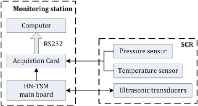
Data acquisition system architecture
The raw analogue data from each sensor have been digitized by a 16-bit data acquisition card (SICSTM S-7017) and the sampling rate has been set at 10 Hz. The pulse signals from a couple of transducers are pre-processed by LC HN-TSM main board, which measures the difference in the time between ultrasonic beam passed upstream and downstream and enables the capabilities of converting and recording the flow rate and this data can be acquired by S-7017 afterwards via an interface.
Then the digital signals of three channels are transmitted to an Industrial Personal Computer (RTCHIP EBOX-D5251), where the data are initialized and recorded. The embedded software has been developed with C code based on multithreaded programming method. Main display interface shows real-time results of HLFCs.
VI. Measurement Results and Discussion
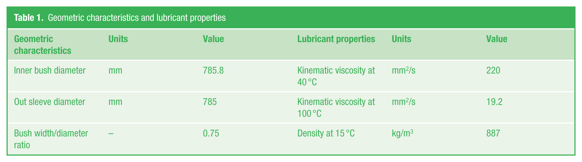
Since it is not possible to bring the whole production line to a standstill to install the SCR specially, the installation of SCR had to be carried out in the overhaul period, which is a time-consuming task. Simultaneously, cable wiring, scene distribution facilities and mounting bracket have been established. Monitoring station has been transported to the installation site soon afterwards. The on-site installation photograph can be seen in Figure 6 . RHMS has been used for an online monitoring of HLFCs under a series of rolling conditions. Bearing geometric characteristics and lubricant properties are listed in Table 1 .
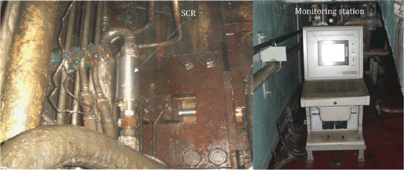
Installation of RHMS in Baoshan Iron & Steel Co. Ltd
Geometric characteristics and lubricant properties
A. Transient conditions
Typical results of HLFCs of journal bearing in tandem cold mill response to a step-type input signal are shown in Figure 7 . P represents a quick response of hydrodynamic lubricant supply pressure and it is very similar to the transient response to a unit-step input of a practical control system. It can be observed that there is a great change in this “transient response characteristics” of feeding pressure. The maximum percent overshot Mp is 2.7%, which directly indicates the relatively stability of the hydrodynamic lubricant feeding pressure system.
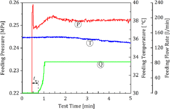
HLFCs under transient conditions
T is the change in hydrodynamic lubricant supply temperature, which tends to decrease slowly and is stable under 36 °C, because the initial environment temperature in the SCR and the feeding temperature are very close.
As expected, Q shows the same rate of change of hydrodynamic lubricant supply flow rate as the supply pressure. This value is controlled at approximately 82.83 L/min. The delay time value tw is decided by the measuring characteristics of ultrasonic flowmeter in order to ensure that the pipeline is filled with the measured medium.
B. Rolling conditions
Hydrodynamic feeding pressure usually could be neglected once it has been regulated by the pressure regulator. Furthermore, there is no access to obtain the real-time data. The actual feeding pressure data under rolling conditions are hard to be acquired. Online monitoring results of hydrodynamic lubricant feeding pressure under rolling conditions are presented in Figure 8 together with the variation of feeding temperature. As can be seen from Figure 8 , each pressure cycle corresponds to a temperature cycle. The feeding temperature moves downward dramatically with the emergence of the feeding pressure pulse. There appear two pressure steps before the feeding temperature moves upward again. From the perspective of the rolling process, each pulse of feeding pressure indicates the process of changing working rolls, and the rolling time of this working roll can be calculated by the time difference between two peak pressures. Here, it needs to be noted a key point that the roll speed drops to zero in the process of changing working rolls, while the hydrodynamic lubricant feeding system is still working. Therefore, the occurrence of feeding temperature points A1, A2 and A3 are the time that rollers start to spin down, whereas points S1, S2 and S3 are the time that rollers stop spinning. In this test, highest feeding temperature is controlled under 44 °C, and the initial feeding temperature of one rolling cycle T1, T2 and T3 are ranging from 39 to 40 °C, which is unacceptable when this value is above 42 °C.
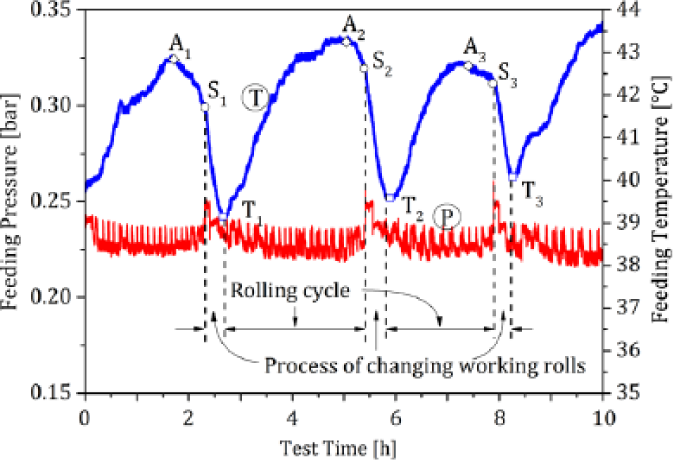
Hydrodynamic feeding pressure together with the variation of feeding temperature under rolling conditions
Hydrodynamic feeding pressure between two pressure peaks (one rolling cycle) under rolling condition is shown in Figure 9 . Feeding pressure is stably ranging from 0.214 to 0.220 MPa in normal rolling conditions. The periodic pressure pulse signal, up to 0.232 MPa, reflects the response to the passing time of welding line. These shock signals occur every 10 min, corresponding to the rolling time of one coil.
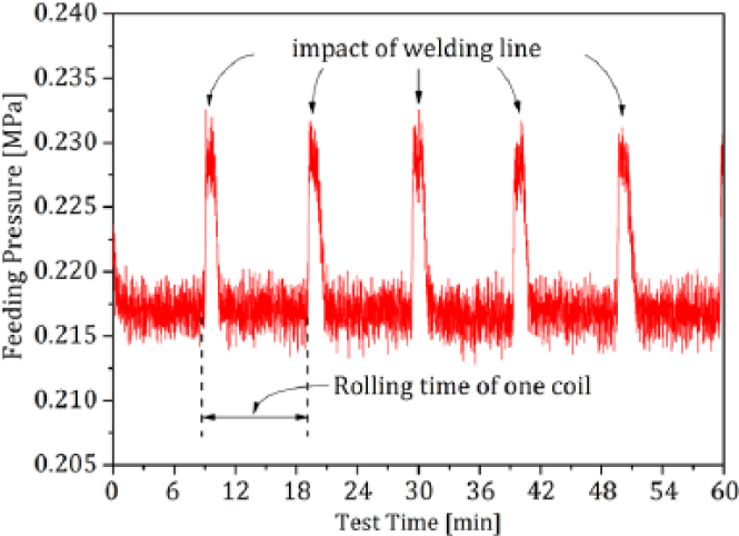
Hydrodynamic feeding pressure in one rolling cycle
C. Emergency stop
HLFCs corresponding to the emergency stop case can be seen from Figure 10 . After a 2.5-h rolling cycle, the hydrodynamic lubricant feeding system was switched off manually and sharp decreases appear in the response curves, both feeding pressure P and feeding flow rate Q decline to zero. Afterwards, the lubricant supply system was restarted and lasted for 10 min.
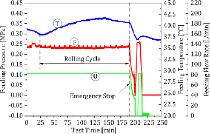
HLFCs corresponding to an emergency stop case
Variation trends of these curves can be observed, sudden increases in feeding pressure and feeding flow rate can be noticed and feeding temperature T shows a steady increase. Again, another downtime was carried on cooperating with maintenance process in the plan and the measured data reflect this process.
Measurement data clearly indicate significant and representative increases and decreases under different rolling conditions. It seems that this experimental work focused on the industrial application made a good effect. According to observed feeding pressure data combined with feeding temperature data and feeding flow rate data, a series of rolling process can be achieved, including rolling time of each working roll, roll change time, rolling time of each coil and start-stop point of this tandem cold mill.
D. Case of failure prevention
Figure 11 depicts the tendency of feeding temperature and feeding pressure against test time, where there existed a great change in the feeding temperature under high speed rolling condition. The strip speed reached 1000 m/min and kept this value until the end of this rolling cycle. The feeding temperature varied from 42.2 to 46.1 °C in 2.5 h, which was out of normal range of temperature control, ranging from 42 to 45 °C under high speed rolling condition. It was observed that the feeding temperature dropped to 43.1 °C at the end of the working roll changing process, which was 1.1 °C higher than the control temperature, and passed to the next rolling cycle immediately. As a result, the feeding temperature reached 45 °C in just about 1 h, which means some steps must be taken to keep the feeding temperature within the control range.
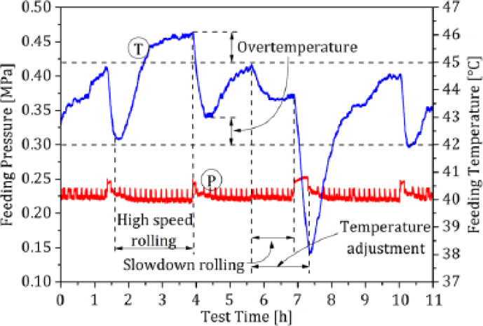
Hydrodynamic feeding temperature adjustment in case of an emergency
Figure 12 shows the schematic illustration of the dynamic rolling speed control method. Specifically, the HLFCs are collected through SCR, and the real-time data are transmitted to the central control room at the same time. The experts in the central control room make a decision that whether it is worth to adjust the rolling speed according to the variation tendency of HLFCs. In the case of Figure 11 , slowdown rolling, at the cost of reducing strip production, has been taken to guarantee that it will not bring the whole production line to a standstill.
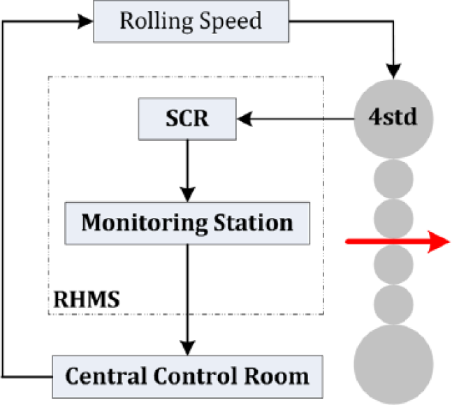
Schematic illustration of the dynamic rolling speed control method
By analyzing the causes of over-temperature, it has been observed that one of the main causes is the short supply of cooling water. Because the rolling technology varies according to the different strip, and high speed rolling is requested in this case shown here. Higher rolling speed (1000 m/min) corresponds to the higher rises in drain oil temperature (in this test, the drain oil temperature is not measured, because it is not a good parameter to monitor 4 ). However, the flow rate of cooling water into the heat exchanger is in short supply and the on-site operator has no idea about the appropriate adjustment range so that the operation have to be depend on experience and feelings. Furthermore, the output temperature of heat exchange has not been collected by the unit’s own monitoring system. The real feeding temperature is more easier to be out of the control range when the adjustment of cooling water supply is neglected by the operator or the adjustment is inappropriate than feeding pressure and feeding flow rate. Additionally, it is impossible to demand the operator to stay near the heat exchanger 24 h a day. In this test, the hydrodynamic feeding temperature is displayed online so that a feedback loop is formed for the engineers to monitor this value, adjusting the feeding temperature and change rolling condition in case of an emergency, as shown in Figure 11 .
Figure 13(a) clearly shows the damage condition of the bush after the over-temperature emergency operation and Figure 13(b) shows the bush after meeting with the online burning accident. The former still had the ability to work to the end of its rolling cycle, whereas the latter brought the whole production line to a standstill.
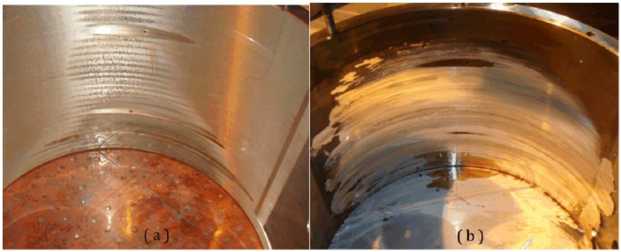
(a) Damaged bush disassembled from the bearing after the over-temperature emergency operation and (b) damaged bush disassembled from the bearing after meeting with the online burning accident
E. Compared with traditional method
RHMS has been installed in September 2013. Compared with traditional method, the main advantage of RHMS is that it not only has the ability to online monitor HLFCs, but also provides an early warning and prevents the happening of the potentially online burning accident so as to minimize downtime and maximize productivity.
Figure 14 shows the bush failure times per year of 1420 tandem cold mill from 2008 to 2014. There has been no more unexpected online burning accident of rolling stand 4 since RHMS was applied. On the contrary, there had been eight online burning accidents in 2011 and consequently caused tremendous losses.
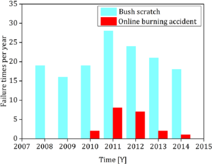
Bush failure times per year of 1420 tandem cold mill from 2008 to 2014
VII. Conclusion
A method, suitable for the industrial field, to monitor HLFCs in the tandem cold mill has been proposed. RHMS has been developed and applied to tandem cold mill. Monitoring results show that the proposed method provides adequate means to monitor HLFCs in tandem cold mill and these parameters have been characterized and proven to be good indicators under different rolling processes. This monitoring method and measuring equipment can be used as a long-term monitoring platform and provide an early warning for the tandem cold mill’s abnormal performance.
RHMS has been put into use for almost 2 years and there has been no more unexpected shutdown of stand 4. In 2014, 22 h of downtime have been saved compared with 2013. The achieved benefits amount to $630,000. However, there still happened an online burning accident in stand 5 in 2014, as shown in Figure 14 . Considering the existing equipment can only monitor one journal bearing in stand 4, in order to obtain more comprehensive data of the entire tandem cold mill (from stand 1 to stand 5), monitoring system needs to be expanded. Additionally, our work has been focused on the condition monitoring of the HLFCs. The failure analysis is all accomplished by the field engineers according to the variation tendency of HLFCs. Therefore, in the future work, multi-point monitoring and automatic fault diagnosis function need to be developed on the base of existing RHMS to improve the efficiency. The future work will be further evaluated from the view of monitoring efficiency and the percentage of accuracy of failure analysis.
Footnotes
Acknowledgements
The authors gratefully appreciated the good collaboration with the local team on site.
Funding
The author(s) received no financial support for the research, authorship and/or publication of this article.