
Abstract
In this paper, the issue of improving control performance of a network-based control system in a different perspective from control algorithms was fully addressed. Some important performance-affecting elements including design of network architecture, configuration, and delay compensation were investigated and some methods presented. The presented design and implementation of a network-based cascade control system with a real laboratory pilot plant involved adopting two different control approaches based on Foundation Fieldbus and Ethernet, respectively. We presented some practically feasible approaches to improve control performance of the system, including improved function block configuration scheme, synchronization control methodology based on IEC61499, output estimation algorithm based on neural network, and methods for reducing network transmission by improving hardware and network architecture. Control effects under the proposed methodologies were also given. Experimental and on-site practice validated these methodologies.
I. Introduction
The development of communication network and technology has brought many remarkable changes to traditional control fashion in modern industries. IEC802.3 Ethernet and field-based intelligent controls are playing an active role in modern industrial automation with greatly improved functions and performance but at a much reduced cost, offering more flexible and practical approaches to solve problems. Fieldbus is the foundation of field-based intelligent control with its highly reliable, deterministic real-time performance in communication between field instruments. Foundation Fieldbus (FF) is one of the most popular fieldbus widely used in industrial process control. Two prominent features of FF lie in its Function Block (FB) scheme and cyclic scheduling strategy, enabling entirely distributed control based on field. As for IEC802.3 Ethernet, it is a quite suitable communication fashion for higher levels in industrial automation architecture. Networked control system (NCS) is mainly based on it, in which closed loop controls are implemented in upper-level controller while data acquisition and device actuation are distributed in field. However, non-determinism and time delay in communication transmission often cause degradation in control effects. Many researchers have explored and investigated improvement methods from the perspective of control science, such as studies on maximum allowable transmission for control and various controller parameters tuning algorithms.1–3 João P. Hespanha and colleagues reviewed several recent results on estimation, analysis, and controller synthesis for NCSs. The results surveyed address channel limitations in terms of packet-rates, sampling, network delay, and packet dropouts.4–9 The above-mentioned studies are mainly focused on theoretical analysis and computation in terms of system stability and control algorithms. Issues of their practical effect and feasibility are not mentioned or addressed. In practical and theory–practice combined design, A. Fadaei 10 presented a practical network platform to design and implement a networked-based cascade control system linking an FF controller and a Siemens programmable logic controller (PLC) through Industrial Ethernet to a laboratory pilot plant. Q. Li 11 investigated delays associated with the use of FF H1 networks within control loops. Y. Pang and H. Nishitani’s 12 research pointed out that the execution time of FBs and the margin time are dominant over communication delays in FF fieldbus. The above-mentioned study showed the variety and diversity of means to achieve that goal.
Actually, NCS is a complex composition including many different elements such as network hardware selection and deployment, software configuration, parameters setting, and so on. Bottleneck in any part of the system can cause degradation of control performance. This, most often than not, can cancel the improvement by control algorithms. Therefore, not only the control algorithm but also other performance-affecting elements of an NCS must be fully considered when a practically feasible network-based measurement and control system is designed and implemented.
In this paper, we address the issue of improving control performance of a network-based control system in a quite different perspective from control algorithms. Some important performance-affecting elements such as design of network architecture, configuration, and delay compensation are investigated and some methods to improve control performance based on these are presented. Two different designs and implementations for a traditional cascade control system based on FF and IEC802.3 Ethernet were, respectively, presented. Degradation in control effect of the NCS caused by network transmission time delay was investigated. Measures to improve control performance by reducing or compensating network transmission time delay in terms of network configuration and control algorithms were proposed. All the methods proposed here were proved practically feasible.
II. Experimental Control Systems
A. Architecture and configuration of experimental control system
The control strategy of the pilot control system is chosen as typical cascade control. The testbed involving two cascaded tanks is shown in Figure 1 . In this system, a water-level loop is applied with a level detector LD302 and a primary proportional–integral–derivative (PID) control to maintain the level stable. A flow loop is applied with a flow transmitter, also in the form of LD302, and a secondary PID control to maintain the feeding water flow stable.
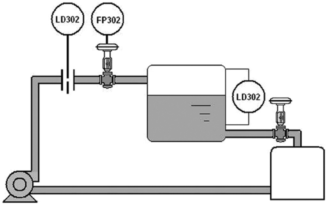
The testbed for a typical cascade control system
Here, we presented a hybrid control system architecture involving FF (31.25 kbps) subsystem and IEC802.3 Ethernet (10 Mbps)-based networked subsystem at the same time. The system is shown as Figure 2 .
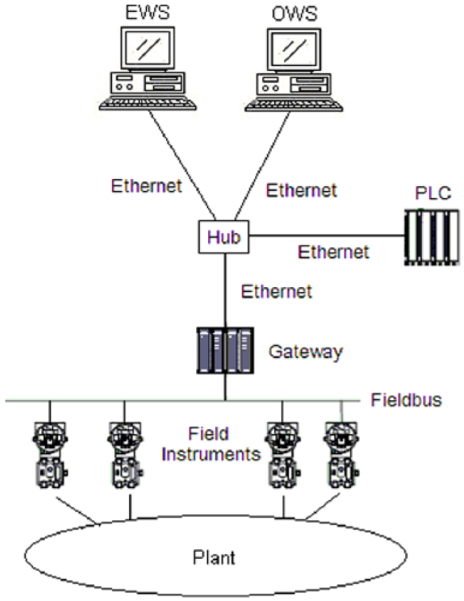
The proposed hybrid control system architecture involving FF subsystem and IEC802.3 Ethernet-based networked subsystem
FF subsystem was composed of upper supervisory computers, gateway module DFI302, and field intelligent instruments including flow/level transmitter LD302 and fieldbus-to-pressure converter FP302 connected with each other by FF H1 fieldbus. IEC802.3 Ethernet-based networked subsystem was composed of supervisory computers, Siemens S7-300 series PLC, gateway, field intelligent instruments, and FF H1 fieldbus. The gateway served as a common intersection in topology by connecting FF intelligent instruments with supervisory computers and PLC. IEC802.3 Ethernet was used as a common transmission network as well as shared by PLC and FF Control System (FFCS). Control strategy configuration software is installed in Engineering Workstation (EWS). Human–Machine Interface (HMI) software is installed in Operator Workstation (OWS) for process supervision. An Ethernet hub was applied in connecting supervisory computers, PLC, and gateway module.
B. Implementation of experimental control system with FF fieldbus
All control strategies are implemented and executed entirely within field instruments by means of FB. The principal part of the implementation lies in the control strategy implementation with FB by configuration software installed in EWS. Two different kinds of FB scheme can be configured to fulfill the cascade PID control by fieldbus intelligent instruments, as shown in Figures 3 and 4.
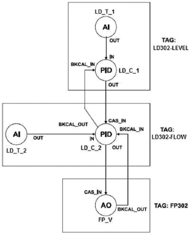
Function blocks configuration scheme-I for cascade PID control
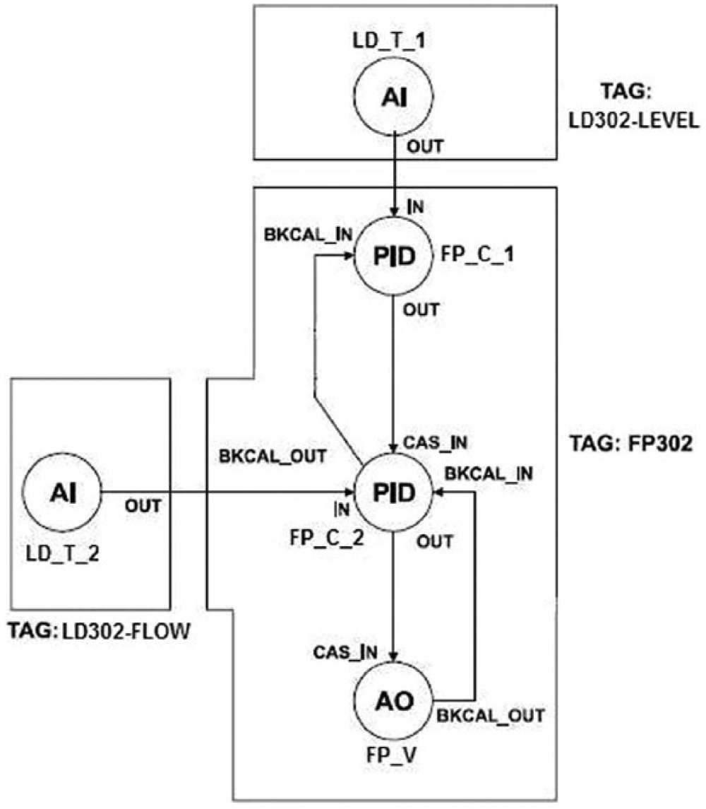
Function blocks configuration scheme-II for cascade PID control
From the figures, it can be seen that all connections and parameters of the FBs involved are the same, while the distributions of the FBs within the field instruments are quite different. In both figures, rectangular blocks represent different instruments with some FBs included. No communication via fieldbus network takes place when connected FBs are allocated within the same instruments, and no network-induced transmission delay happens for data exchange between these FBs. Therefore, configuration scheme shown in Figure 4 reduces the fieldbus network transmission time and consequently makes the control cycle shorter.
Various process parameters can be monitored in the form of graphic or text display by HMI. Fieldbus OPC server is essential in the implementation of data communication between the field and upper supervisory level. Data transmission process between field and supervisory levels is shown in Figure 5 .
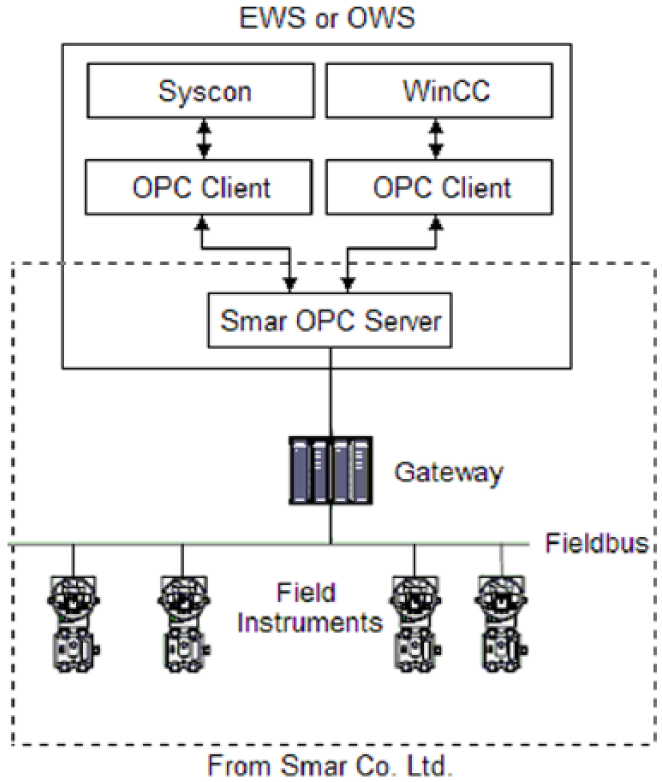
Data transmission process between field and supervisory levels
The level set-point is set to 50% to check the process response in this control fashion. The obtained response result is shown in Figure 8 .
C. Implementation of experimental control system with IEC802.3 Ethernet
In the Ethernet-based control system, it is the PLC that plays the main role with all control strategies implemented and executed within it. Fieldbus intelligent instruments only serve as remote digital I/O modules for data acquisition and control move actuation. The communication between the PLC and gateway is via Ethernet Modbus link. The essentially important part in implementation of this control fashion is to achieve data exchange between PLC and field intelligent instruments. Here, we use a new FB Modbus Control System (MBCS) provided by the gateway DFI302 to combine the fieldbus subsystem and PLC closely in a simpler but more flexible way.
The MBCS block 20 generates a communication strategy between a Modbus master and a Fieldbus Foundation slave. In this case, the slave is the gateway DFI302. It allows Modbus variables to be associated with Fieldbus variables and data to be exchanged through DFI302. The architecture of the control system involving PLC, DFI302, and MBCS FB is shown in Figure 6 . Control strategies are located in PLC. Field data acquired by intelligent field instruments is sent to the PLC, and control move is sent by the PLC to intelligent actuator with MBCS as the data exchange interface.
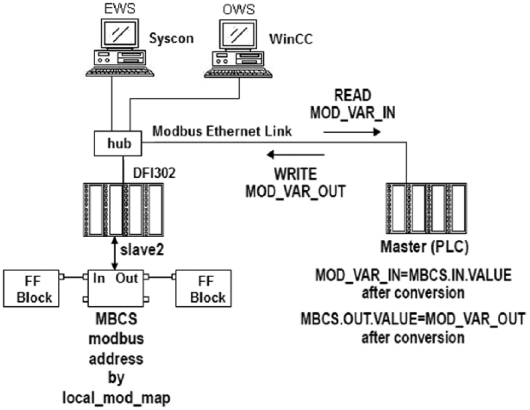
Architecture of the control system involving PLC, DFI302, and MBCS function block
Some extra strategies need to be configured for Fieldbus subsystem in order to exchange I/O data with PLC by means of FB MBCS and Modbus Ethernet. The control strategies configuration for Fieldbus subsystem based on MBCS provided by DFI302 is shown in Figure 7 .
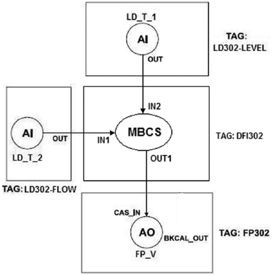
Control strategies configuration for Fieldbus subsystem based on MBCS
The level set-point is set to 50% to check the process response under this control fashion. The obtained response results are shown in Figure 8 .
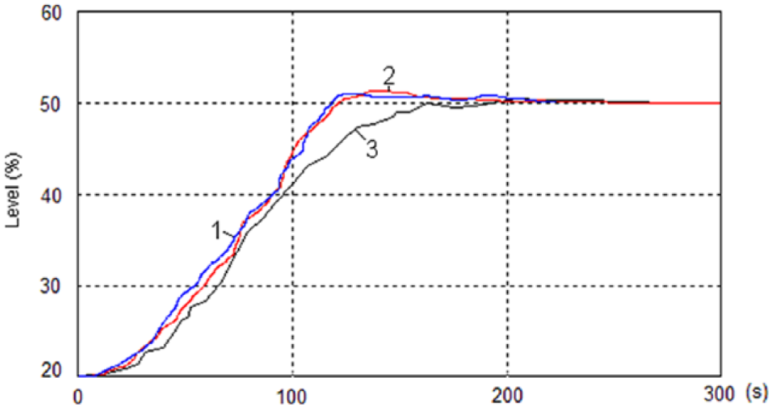
Step response for level set-point disturbance with control system involving PLC, DFI302, and MBCS function block
From the step responses, it can be seen that FF fieldbus-based control system with FBs configuration scheme-I had the best performance and the IEC802.3 Ethernet-based control system had the slowest response since its involved communication delay is the longest one.
III. Analysis and Improvements
A. Analysis of effects on control by time delay in transmission
Actually, data transmission time delay consists of two different parts: (1)transmission time delay caused by microprocessors’ data processing within computers or field instruments and (2) transmission time delay caused by data transmission over communication links. Generally, the former is often ignored because the microprocessors’ processing speed is much faster and much less when compared with the latter. Therefore, transmission time delay caused by communication links is the principal element.
FF Fieldbus-based control system
From the control system implementation scheme based on field intelligent instruments, it can be seen that each FB within control strategy is executed serially and deterministically in chronological order by scheduling. This kind of mechanism makes sure that downstream FBs will be executed only after the required data from upstream FBs. If not, the status values of FB inputs will indicate an error, which will trig an appropriate handling process by the FBs. When distributed control strategies are scheduled, control moves to actuators are scheduled at the end of this cycle. FB AI is scheduled at the beginning of the next cycle. Thus, control moves are always prior to feedback from plant, which ensures the correct timing sequence in control.
Therefore, no mismatch and asynchrony between the control moves and the feedback exist in fieldbus-based control scheme, thanks to its cyclic FB scheduling. Only some minor transmission time delay, which is deterministic and can be predicted based on the fieldbus communication speed and numbers of FB to be scheduled, takes place over the fieldbus between two consecutive control moves.
IEC802.3 Ethernet-based NCS
In this fashion, transmission delay is mainly caused by Ethernet. It occurs on two paths, including a downward path on which data are downloaded to the field and an upward path on which data are uploaded to the controller. The two paths correspond to control channels and feedback channels, respectively. Data transmission delays in control channels and feedback channels are represented as
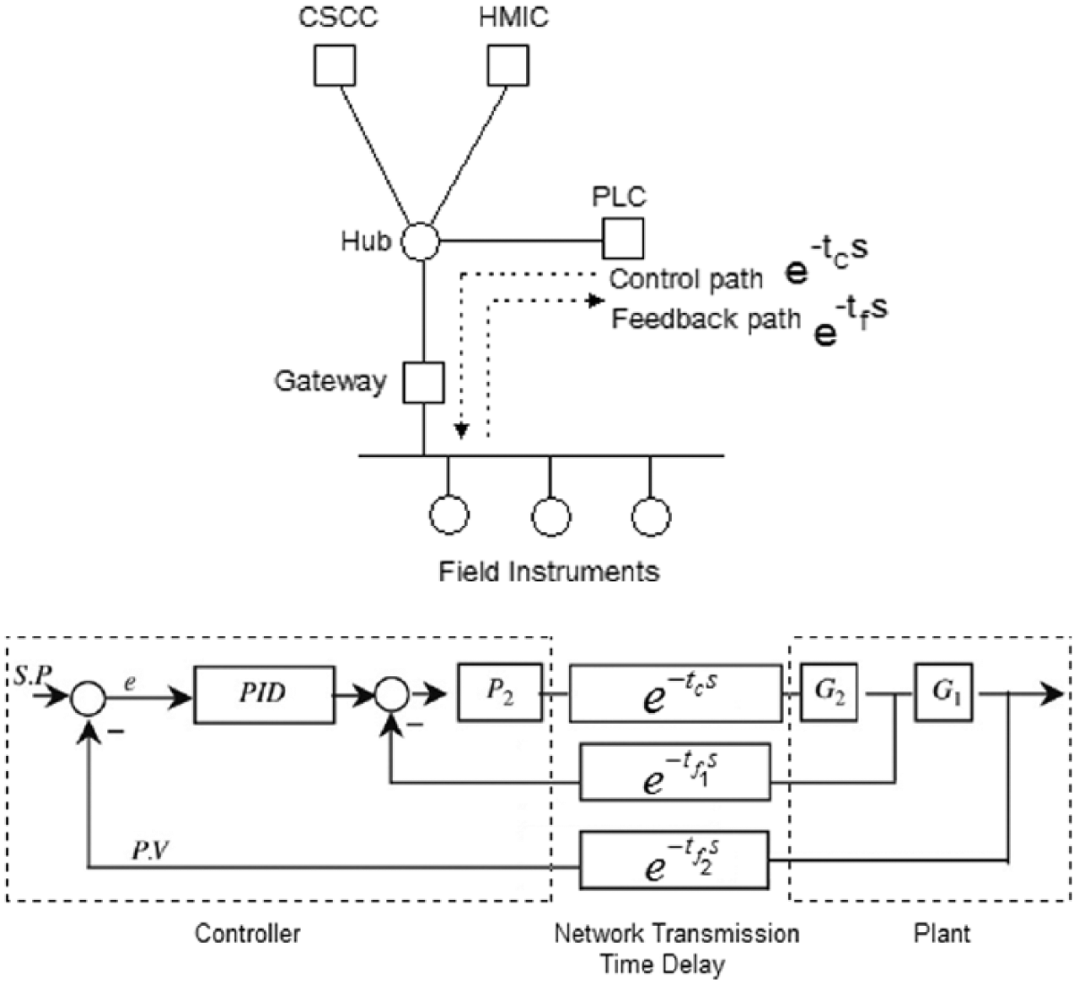
Transmission time delay in control channel and feedback channels
Some researchers investigated the degradation of control effects caused by Ethernet transmission time delay and pointed out that increasing transmission delay reduces the rising time and degrades the steady state response for typical PID cascade control. 4 The conclusion was based on the assumption that control moves are generated continuously despite of the delayed control moves and feedback. Degradation of steady state response can be mainly attributed to asynchrony of control moves and feedback under the circumstance of continuous control.
B. Improvement measures for control effects in IEC802.3 Ethernet-based NCS
To improve control effects degraded with network transmission time delay in IEC802.3 Ethernet-based case, two problems should be considered. First, the asynchrony between the control moves and the feedback caused by transmission delay should be reduced as much as possible. Second, network transmission delay itself should be reduced by means of hardware or network architecture improvements. Alternatively, some compensation methodologies in perspective of control theories can be applied in order to counteract the effect of the transmission delay.
Reducing asynchrony between control and feedback caused by transmission delay
As mentioned above, asynchrony between the control moves and the feedback mainly existed in NCS fashion. Therefore, the solutions proposed in this section are used for Ethernet-based NCS fashion.
Synchronization control is necessary to reduce asynchrony between the control moves and the feedback caused by transmission delay. IEC61499, an international standard for fully distributed process control, provides a synchronization control mechanism for NCS fashion. 21 Since it is based on event-triggered mode, some specific events can be correctly set for PID blocks in PLC to control the synchronization between the control moves out of PID blocks and the feedback into PID blocks. PLC programming compatible with IEC61499 is supported with some of the Siemens products. Here, we propose a methodology to realize the synchronization control based on IEC61499.
Events need to be configured to control the synchronization between feedback data acquisition and control move. To control the sequence between data acquisition and control algorithm execution, event signals in PID block need to be configured. The configured event in PID block will not be triggered until the feedback from the plant over Ethernet is fully available at the inputs of PID blocks by means of data acquisition block. The event is triggered by the data acquisition block upstream to PID block. Therefore, PID control algorithm will not be executed and no new outputs are generated if the event is not triggered. As for feedback, the acquisition of data from field will not be executed only if the control moves by generated PID blocks are sent to field. To achieve this, an event signal is dispatched to the data acquisition block by the control moves output block to control the sequence. The data acquisition block and the control moves output block are user-defined blocks that can be programmed with five standard languages specified in IEC61131-3. The schematic of the proposed methodology is shown in Figure 10 .
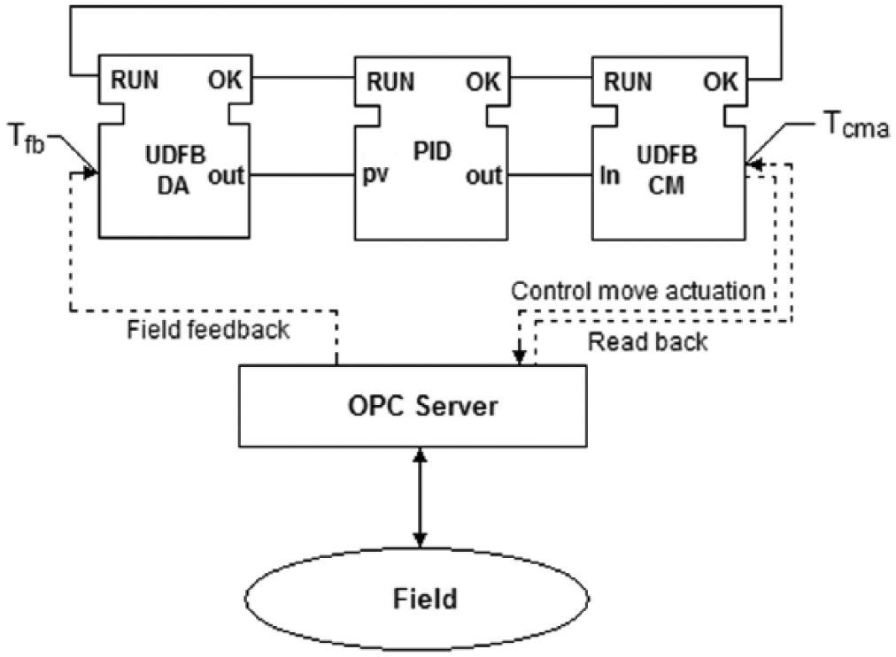
Schematic of the proposed methodology based on IEC61499
In configuration, the proposed scheme consists of a User-Defined Function Block for Data Acquisition (UDFB-DA), a PID block compliant with IEC61499, and a User-Defined Function Block for Control Moves (UDFB-CM). Two global time variables
Flow chart of the proposed scheme based on IEC61499
The main function of block UDFB-DA is to control the sequence of feedback acquisition and control move to make it deterministic that control move is prior to feedback acquisition in each execution of control strategy by means of global time variables
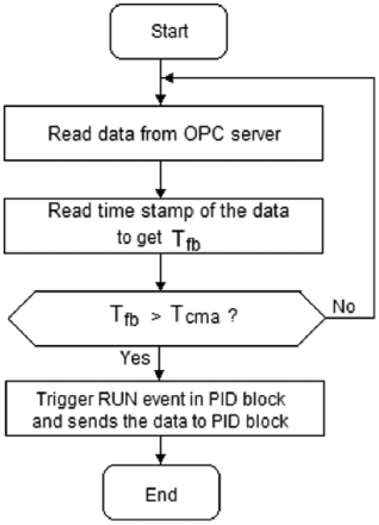
Execution control logics of UDFB-DA
The execution control logics of PID are shown in Figure 13 .
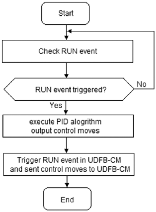
Execution control logics of PID
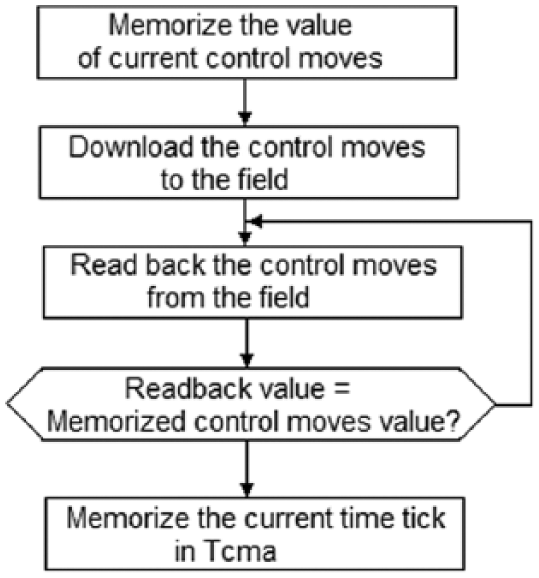
The main functions of block UDFB-CM are to download the control move generated by PID block to field and record the instant when the download and actuation are finished. Readback check is used to make sure that the control move has been downloaded to the field successfully. The execution control logics of UDFB-CM are shown in Figure 14 .
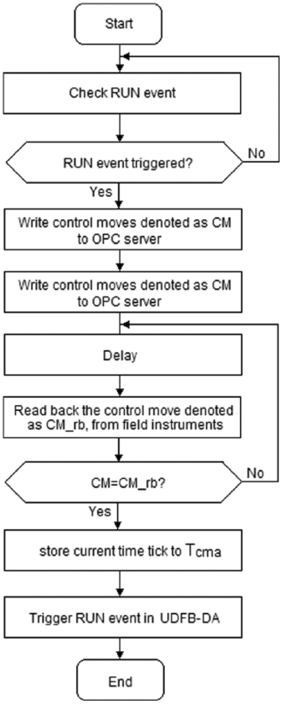
Execution control logics of UDFB-CM
The level set-point is set to 50% to check the step response under this improved control fashion. The step response results are shown in Figure 15 .
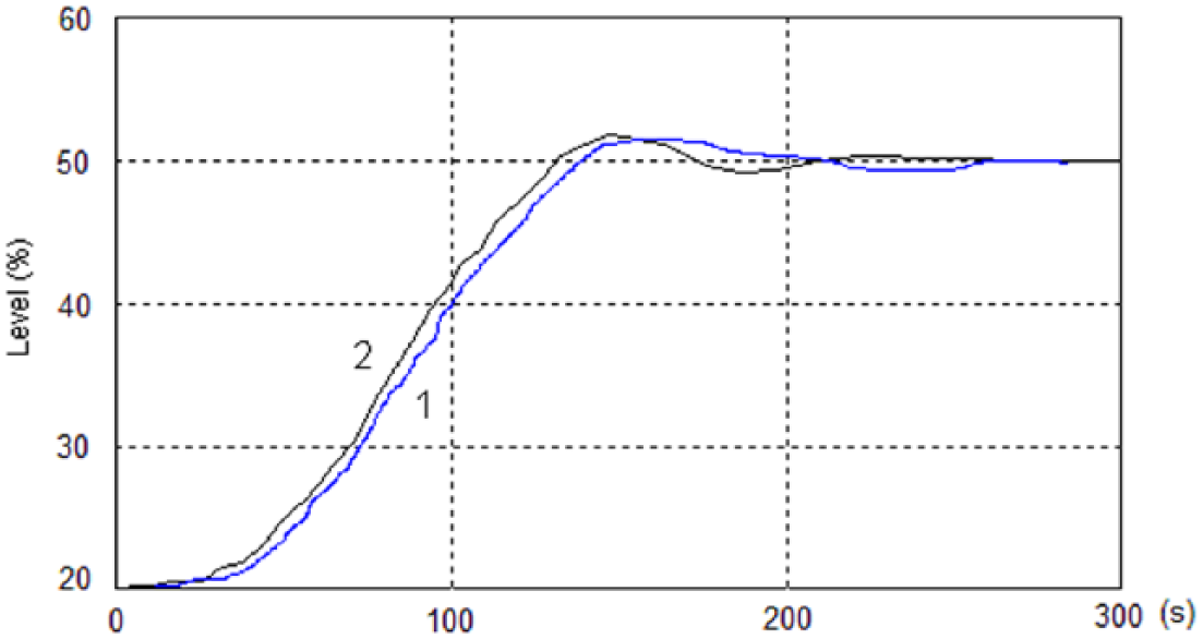
Step responses for level set-point disturbance with the Ethernet-based control system and PLC using the proposed control scheme based on IEC61499
Using output estimation to compensate for the transmission delay in feedback
Transmission delay in feedback path will cause the feedback data from the plant field not updated within certain time-span. This can be observed by upper supervisory workstation (OWS or EWS) by means of “time-stamp” property of data acquired by OPC server. Since the maximum time delay caused by the IEC802.3 Ethernet cannot be predicted while regulation must be continued to keep system stable, it is necessary to obtain estimation of the output of plants to take the role of the real output which is not available at current instant. Here, we proposed an output estimation scheme based on neural network. Neural networks are used to predict the output of plant. In this case, predicted output by neural network instead of the real one is used as inputs of block UDFB-DA to be sent to PID to generate control moves.
Schematic of output estimation with neural network is shown in
Figure 16
. In this scheme, a neural network estimator (NNE), with one input layer, two hidden layers and one output layer, is used to estimate the output of plant in case the up-to-date output of plant cannot be obtained from OPC server within certain time limit
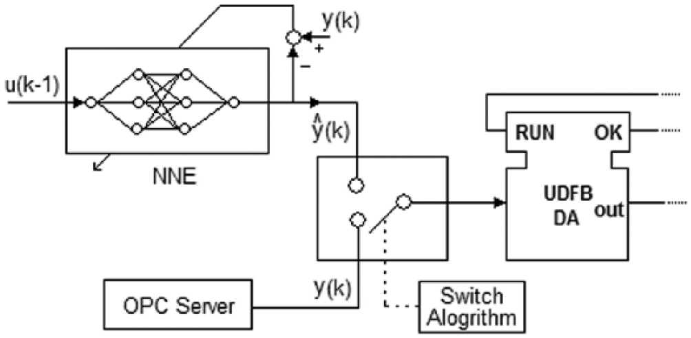
Schematic of output estimation with neural network
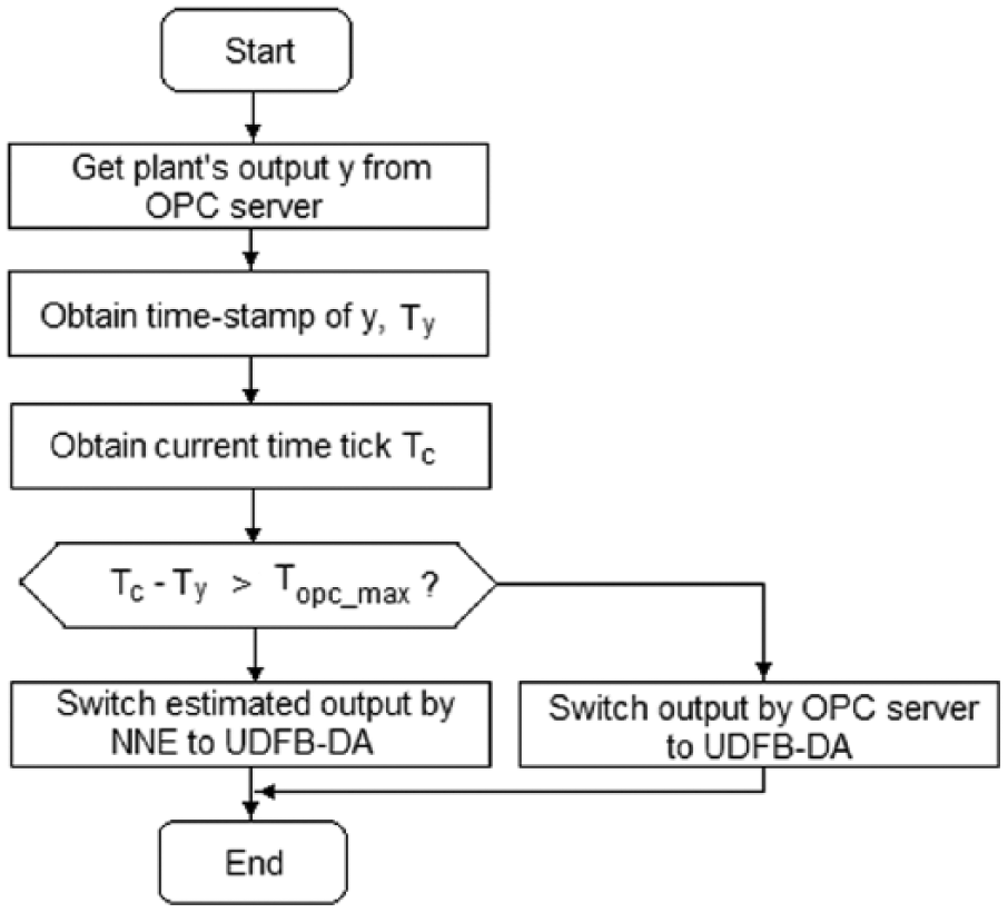
Flow chart of switching algorithm
The advanced control FB such as the NNE and the output FB should be configured within the same module. It is feasible and practical with many NCSs such as FF system. Under such condition, no data transmission over network is needed. Data transmission is conducted within the configured module itself. Only measurements are transmitted over network to the controller. Otherwise, the action commands produced by the controller would have to be transmitted through the same network to the actuators. So they would be subjected to the same delays and non-determinism.
Reducing network transmission by improving hardware and network architecture
Because the network communication over IEC802.3 Ethernet is based on carrier sense multiple access/collision detection (CSMA/CD) mechanism, the time non-determinism of data communication between different nodes increases greatly with network traffic load. Here, we propose two principal ways to reducing network transmission delay itself by improving hardware and network architecture besides raising the whole network communication speed:
1. Dividing Ethernet network into different segments based on time-critical requirement rating to leave more bandwidth to time-critical communication
Available bandwidth for time-critical communication, such as that between PLC and DFI302 here, is in reverse proportion to the number of nodes connected within the segment. However, priorities of communication among nodes are quite different within. Data transmission between PLC and DFI302 is quite time critical for its control function, while that between OWS, EWS and PLC is not, since only setting point data and some supervision-based data need to be exchanged. Therefore, communication between nodes should be grouped and rated based on their time-critical requirements. And then, the whole network is divided into several different segments using router to allocate the nodes involved in different communication priorities into those segments. Traffic load within the segment is lowered greatly and efficiently since bandwidth contention from nodes outside local segment is blocked. Besides, broadcasting data flow within the same segment is also effectively blocked and screened.
As far as the control system investigated in this paper is concerned, communication between nodes can be classified into two groups based on their time-critical requirements. One group is the non-time-critical communication including that between OWS, EWS, PLC, and other computers. The other is the time-critical communication, namely, data transmission between PLC and DFI302. The two groups are divided into two different network segments with different subnet mask and gateway configuration, by means of a router. Nodes in each segment are interconnected by means of a hub. The corresponding schematics of network structure and subsections according to the scheme proposed above are shown in Figure 18 . The corresponding network configuration for each segment and node is shown in Table 1 .
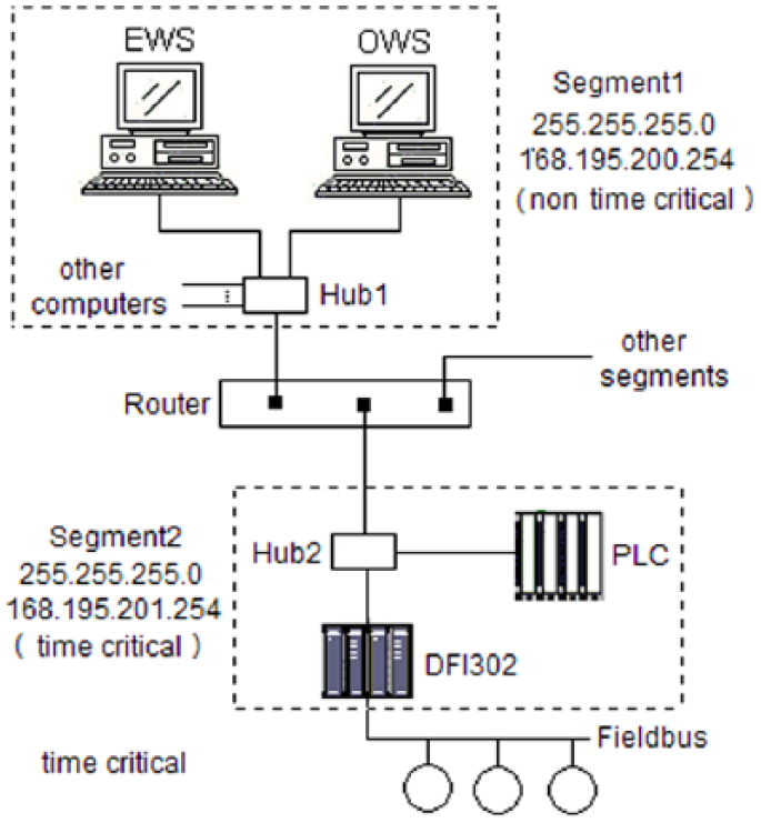
Schematics of network structure and subsections
Network configuration for segments and nodes
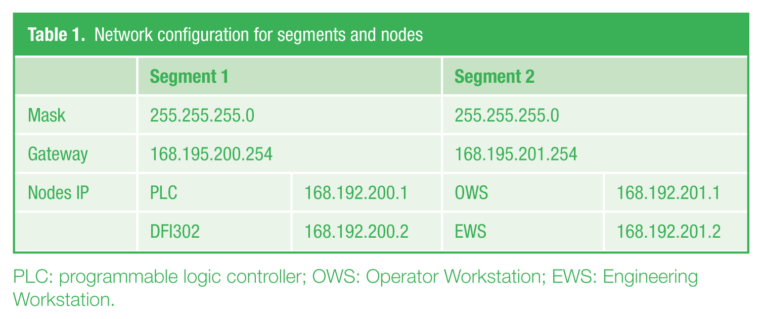
PLC: programmable logic controller; OWS: Operator Workstation; EWS: Engineering Workstation.
Obviously, it can be seen from Figure 18 that broadcast storms from other segments are blocked outside the segment 168.192.201.*, in which PLC and DFI302 reside, by the router and no bandwidth contention from any node in segment 168.192.200.* or other segments comes up. Full bandwidth in segment 168.192.201.* is available to the communication between PLC and DFI302, which ensures the stable and reliable data exchange between them in turn.
2. Reducing transmission delay from store-and-forward by related network components
With no sense of priority, an industrial telegram, which may be critical for real-time control, might be delayed for some switch’s store-and-forward buffer waiting for an IT telegram to pass through. First, as the telegram passes through the switch, it gets stored in a buffer until the entire message is received; only then it is forwarded out of the switch. Second, if the industrial message arrives at the switch at the same time the switch is processing an IT telegram, it must wait until the entire IT telegram passes through the switch before it can move on. Because a frame with a higher priority is always given precedence, automation frames are delayed if the queue buffers are filled with frames that have the same or higher priority. And, automation frames can be delayed for an unpredictable amount of time. There may also be congestion at the switch’s output port: When the output port is filled with frames, high-priority frames have to wait until the port is available again. The solutions are to, first of all, pass all automation telegrams straight through the switch, bypassing the store-and-forward mechanism. Second, if an industrial telegram arrives at a switch while an IT telegram is being processed, that processing stops immediately and the industrial telegram is given clearance to pass through. After it has cleared the switch, the IT telegram is re-transmitted through the switch. Experiments have shown that the delay for the time-critical industrial messages is over 2000 µs with standard “store and forward” switching, but with the proposed solutions, the maximum delay is only about 50 µs.
IV. Conclusion
The use of a multipurpose shared network to connect spatially distributed elements results in flexible architectures and generally reduces installation and maintenance costs. Consequently, Ethernet and fieldbus-based NCS have been finding application in a broad range of areas. Most of the recent research are mainly focused on theoretical analysis and computation in terms of system stability and control algorithms for NCS. Issues of their practical effect and feasibility are not mentioned or fully addressed. In this paper, we address the issue of improving control performance of a network-based control system in a quite different perspective from control algorithms. Some important performance-affecting elements are investigated and some methods to improve control performance based on those are presented. The main contribution of this paper lies in the fact that the proposed approaches to improve control performance for Ethernet and fieldbus-based network combine practical feasibility into the co-design of control and communication and proved practically usable. Through the research, it can be found that
As for design and implementation of fieldbus system, configuration scheme on allocating FB to different field instruments can notably affect the control performance and is worth paying attention to. Improved FB allocation and configuration scheme can lead to shorter control cycle and thereby more efficient control.
No essentially indeterministic data transmission delay was involved and thereby no degradation caused by it in control when control strategies were implemented with fieldbus control system by means of FBs and full distribution in control was achieved, which demonstrated the apparent advantage over general NCS. No mismatch and asynchrony between control moves taking real actions and feedback being generated exist in Fieldbus-based control scheme, thanks to its cyclic FB scheduling. Degradation of steady state response can be mainly attributed to asynchrony of control moves and feedback under circumstance of continuous control as far as the Ethernet-based control system is concerned.
Methodologies based on IEC61499 proposed in this paper can be utilized to control the execution sequence of each FB in PLC controller with events and some specific action control logic. The proposed output estimation algorithm based on neural network can also compensate for the transmission delay in feedback effectively.
It is an effective and efficient way to reduce network transmission delay itself by improving hardware and network architecture. Dividing Ethernet network into different segments based on time-critical requirement rating and reducing transmission delay from store-and-forward by related network components are proposed to achieve this aim.
Consequently, many problems existing in networked control, in which communication and control technologies are involved at the same time, can be solved to a great extent by means of network-related methodologies which provide alternative or most possibly comprehensive solutions.
Footnotes
Funding
This study was supported by Beijing Natural Science Foundation (4122074), the Fundamental Research Funds for the Central Universities (11MG12) and the National Natural Science Foundation of China (61174116).