
Abstract
For as long as oil has been produced, techniques have been developed to control flow, and choke valves are an integral element of this vital requirement. This paper explores the history of the industry’s move from surface to subsea production and the translation of topside choke valve technology to the more challenging, underwater environment. It considers the types of valves available for different operating conditions and the importance of specifying a valve correctly to avoid early deterioration, costly maintenance or production outages. It explores the future challenges that the oil and gas industry faces and the advances in control valve technology that will support the ongoing development of seafloor processing techniques.
I. Introducing Choke Valve Technology
A choke valve is a mechanical device that induces restriction in a flow line, causing either a pressure drop or a reduction in the rate of flow. See Figure 1 .
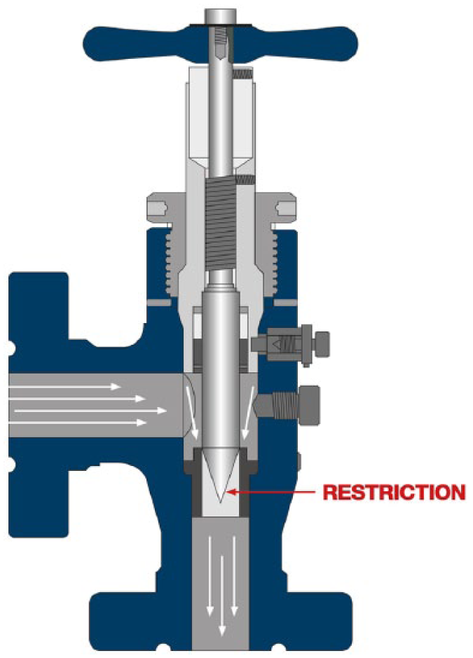
Choke valve cross-section
In the context of the upstream oil and gas industry, choke valves are used wherever there is a requirement for wellhead flow and pressure control.
Examples of such requirements include the following applications:
Oil production platforms;
Gas production platforms;
Surface wellheads;
Subsea trees;
Surface manifolds;
Subsea manifolds;
Onshore oil wells;
Floating Production, Storage and Offshore Loading vessels (FPSO).
A production choke valve will typically take up to 40,000 barrels of oil a day and must control start-up, running and shut-down processes.
The fluids controlled by choke valves will be well fluids, or production hydrocarbons, containing a mixture of fluids such as oil, gas, water, sand, H2S and CO2.
In each application, the mixture of fluids will be unique to the individual operating environment and will change over time as production continues. Careful control of the flow of the well fluids is needed to avoid any production well formation damage. Gas will be situated on the top of the mixture, being the lightest; the oil floats on the water. Initially, at the start of a field’s life, the highest pressures are experienced; some fields can have a large gas cap. If this gas is wet and the pressure drop is significant, it can freeze up, through the unintended production of hydrates, leading to a freezing or waxing-up of the whole field. In these cases, methanol and glycol (MEG) is used to thin the mixture and prevent hydrate formation.
To improve yield, gas can be injected into the oil stream producing bubbles (‘gas lift’). The bubbles expand as they get closer to the surface, reducing the pressure and improving the ability to lift the oil and gas.
Field service lines and pipeline transmission lines are generally low pressure and require proper sizing for distribution of the fluids produced. Choke valves are an essential part of balancing these requirements. The controlled release of reservoir fluids through proper flow and pressure regulation will maximise the life of the reservoir and the recovery of valuable oil and gas products.
II. Types of Choke Valve
A positive choke has a fixed orifice size. Although fixed chokes are available in a wide variety of sizes and types, the choke must be disassembled to change bean sizes. The term ‘bean’ refers to the piece of hardware installed in the line that has an orifice, or opening, drilled into it. The bean size is the inside diameter (ID), or bore, of the fixed orifice. These bores are available in 1/64th of an inch increment.
An adjustable choke provides variable orifice sizes through some type of external adjustment device, such as an actuator. This arrangement will accommodate a range of conditions, from a uniform pressure drop to a variable inlet pressure drop.
An injection choke is used to control water, gas or chemicals injected back into the well to force/stimulate oil or gas to the surface or aid flow assurance.
It should be noted that surface choke valves are rarely mounted vertically, contrary to popular belief. They are much more likely to be mounted so that flow arrives from the side. Subsea chokes valve can be installed vertically or horizontally dependent on the tree/structure installation.
III. A Brief History of Subsea Oil and Gas Production
In the early days of oil production in the 1840s, oil, being in plentiful supply and easily accessible, was pumped from beneath the surface by wells placed topside. With the advent of mass production came the development of choke valve technology to control production flow.
The first subsea processing took place as early as 1947, but only to depths of 15 m initially, via surface-based steel-framed rigs. With advances in understanding of the challenges involved and the identification of reserves at much greater depths, by the 1970s, depths had extended to 250 m and to almost 1500 m by the dawn of the new millennium, via semi-submersible platforms.
However, it is not possible to simply run a pipeline down to the seabed at depth. Furthermore, building oil platforms is, of course, fearsomely expensive. In moving to subsea wells, the industry initially looked for ways to re-use or adapt existing platforms to accommodate deepwater applications. In time, FPSOs (essentially converted oil tankers) and TLP (tension leg platforms) made more commercial sense. These structures require the placement of subsea trees and subsea equipment on the seafloor from where oil and gas can be piped back to a rig or ‘tied back’ to an FPSO. They therefore allow production in much deeper water in a more cost-effective manner.
The creation of subsea infrastructure is not without its peculiar challenges, however. While at the surface plant is laid out in a neat, modular way, subsea, the topography is much more complex, with uneven sea beds and even seafloor mountain ranges to contend with. But these are not the only problems the industry has had to solve.
IV. Applying Topside Technology Subsea
There were – and continue to be – a great many considerations in transferring choke valve technology away from a topside and into a subsea environment.
Subsea, external pressure increases 1 bar for every 10 m depth. Operating at 3000 m, the pressure will therefore be 300 bar (4350 psi) – this is the hyperbaric effect. (It should be noted that the ambient temperature is normally 4 °C at this depth and a stable condition.)
Other challenges will vary, dependent on the production location, and will variously include the following:
Corrosion and erosion – especially from gas, sand and rock;
Sea currents and stagnant conditions – especially critical during the time equipment is being lowered onto the seafloor and being run on wires or by crane;
Calcareous and marine-life growths on subsea equipment;
Maintenance costs and accessibility – it costs upwards of £250 k per day to carry out an intervention;
Protection against accidental damage or impact from local fishing activity or even iceberg movement.
V. Design of a Subsea Retrievable Choke Valve
Subsea choke valves are based on topside technology but with critical modifications, including the addition of subsea relief valves and the use of additional sealing technology (metallic and elastomeric seals) to counter external pressures.
Features will include the following:
Solid carbide construction;
High-friction (HF) trims for production applications;
Premium grade trim characteristic (TC) control elements;
TC sacrificial plug nose;
Shrouded plug seat (seating area is protected from the high-erosive flow path);
Hole development dead-band (seating area is moved away from the main flow area);
Metallic ‘brick stopper’ to prevent solids directly impacting the TC.
VI. Use of Trims in Subsea Choke Valves
It is imperative that choke valves are correctly sized and selected, and the correct trim technology is deployed to address these issues. In calculating the required TCs for its ongoing usage, the engineer will need to know the following:
Process conditions;
Size and schedule of connecting pipework;
Capacity/coefficient of variation (CV) calculation;
Start-up conditions;
Standard/future operating conditions;
Process media physical properties;
Whether hydrogen sulphide will be present;
Whether sand will be present;
If injection of clean water or gas will be used.
There is a wide range of solutions in the market, different technology being used to handle everything from very small to very high design CVs and significant pressure differentials (DP). Solutions will accommodate the following:
Design CVs between 0.0013 and 1000;
Pressure drop capability between <1 bar and 800 bar DP;
HF single stage and multi-stage for production applications;
Microspline and multi-spline for MEG and methanol injection;
Shrouded plug/seat design for sandy applications;
Vari-stage trims;
Tortuous path trims.
VII. TC and Capacity
One of the most critical calculations is that of valve trim capacity and flow characteristic. The total combined area of holes gives overall capacity, but where the holes are placed will result in different flow characteristics. See Figure 2 .
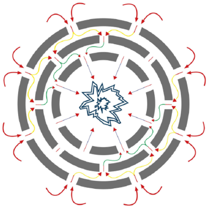
The trim principle
Therefore, if the field demands fine control – very low flow and fine control at start-up – equal CV percentages are used. If a large capacity is required (for instance, when opening the valve 10%, a flow of 10% is required, and likewise, while closing, an equal reduction is required), a linear CV is desirable. See Figure 3 . The eventual solution is, of course, application-dependent.
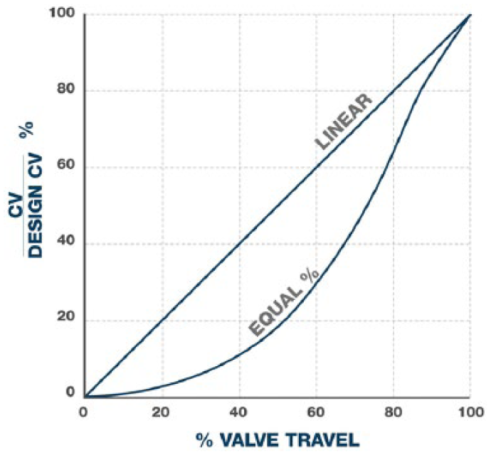
Trim characteristics – linear and EQ%
VIII. Trim Types (Simplest to Most Complex)
A. Needle and seat
Simplest and least expensive adjustable choke valve;
Good pressure control for low DPs;
Reasonable capacity.
B. Multiple orifice valve
Quick open and close (90°);
Good rate and pressure control;
Available as in-line installation.
C. Fixed bean
Best for applications requiring infrequent adjustments;
Used mostly on wellhead Christmas trees.
D. Plug and cage
High capacity;
Good controllability.
E. External sleeve
Reduced capacity when compared to the plug and cage designs.
IX. Subsea Actuation
Each adjustable choke valve requires an actuator to move or control its throttling mechanism. In subsea environments, a stepping-type hydraulic actuator is commonly used. Its features include the following:
Design depth of 3000 m (tested to 2330 m);
3000 or 5000 psi hydraulic supply pressure;
Compatible with various water glycol control fluids;
Top or side visual indicator and override;
Linear, rotary and dual 4–20 mA feedback options;
Bellows or diaphragm pressure- and temperature-compensating device.
X. Choke Valve Criticality
Traditionally, the choke valve is the first and only piece of equipment in the subsea system controlling the well, although typically there will also be a corresponding valve topside (on the platform or FPSO). This is because there could be 250–300 km between the subsea asset and the surface. Many other valves exist in the system but are only carrying out isolation duty – these will be gate or ball valves.
As such, start-up and shut-down considerations for subsea valves are vital. Shut-downs and re-starts can be a regular occurrence in oil production; when export storage capacity is reached, wells might be shut off temporarily or production switched to other wellheads. This is especially true in an FPSO environment, but will also be the case in a rig environment.
If there were only a single valve on the surface, it could take longer to start up the field because of the lack of control nearer subsea well(s). Having a subsea choke as well as a surface choke significantly aids flow assurance.
XI. Valve Maintenance
Because of their critical duty, most valves are designed for 20 years’ field life. Operators have different maintenance options available dependent on factors in the field including water depth and field location.
There are three types of subsea valve, dependent on the conditions in which it will be operating – and the client’s maintenance philosophy.
A. Fixed choke
Non-retrievable in itself – often mounted into a retrievable module. These can be used at any depth.
B. Diver-retrievable
The diver can retrieve the choke insert from the body casing. These can be used up to a maximum water depth of 200 m.
C. Deep water retrievable via remotely operated vehicle
Water depths greater than 200 m require tool-retrievable chokes operated from the surface via a remotely operated vehicle (ROV). The intervention equipment used is known as a running tool. A simple design would include the following:
Primary guidance – funnel and guide chute;
Secondary guidance – post and receptacle;
Soft landing and lock down to funnel;
Two-point tool to choke interface, clevis/pin locked in via T bars, mandrel also used for stability;
Insertion/retrieve via ROV-operable power jack;
1 tonne additional pull or push to overcome any effect of debris trapped in choke or seal friction;
Tool adaptable for guideline or guideline-less requirements.
Optional intervention equipment also includes the following:
Modular skid system designs;
Mono or dual porch options;
Separate or integral offshore test modules;
Debris or protection cover options;
Protection from dropped objects;
Over-trawl protection.
In reality, since diving is a dangerous activity, the requirement for it is reduced where possible. Modern specifications often require a diver installation with ROV maintenance for field life.
XII. Common Problems
A. Corrosion
Valves are designed typically with a 20-year life. However, in this time, the whole valve would corrode as a result of a chemical reaction to the seawater. To counteract the effect of galvanic corrosion (the proximity of dissimilar metals to each while in water), cathodic protection is used. If these metals are in direct electrical contact while immersed, they form a simple battery. Metals that top the galvanic series are the least noble and act as the anode (and corrode), while those more noble metals, further down the ranking system, are protected from corrosion. To facilitate this effect, zinc blocks are used on the subsea ‘Christmas tree’/structure. A small voltage is produced which drives current from the valve body (steel alloy) to the zinc, ultimately causing corrosion of the blocks only.
The zinc blocks are designed for a 30-year life, so they never need replacing. During the subsea choke factory acceptance test, electrical continuity between all valve metallic components are tested with a multi-meter to ensure they are electrically connected prior to valve dispatch.
B. Flashing
When oil and gas combine, they act as a liquid, having a vapour pressure (VP). If the local static pressure falls below the fluid VP, vapour bubbles are generated within the liquid – known as flashing. If the downstream static pressure remains below the fluid VP, then these vapour bubbles will remain in the downstream flow, causing erosion. To overcome this phenomenon, the correct materials must be selected and the application designed to maintain flow at the correct velocity.
C. Cavitation
Even when the outlet pressure is higher than the VP, problems might still arise. If the pressure drops, allowing the liquid to become a gas and bubbles to form – these bubbles will collapse when returning to a liquid state. As this happens, the bubbles tear away at the material used in the valve – this could potentially ruin a valve in a matter of hours, if unchecked. The solution here is to use a low-recovery valve trim and to drop the pressure carefully through the use of trim technology. This will eliminate cavitation and reduce flow velocity to prolong the life of the valve while maintaining an acceptable production rate.
D. Erosion
This takes place when physical materials such as sand are present in the pipeline. Using solid carbide would protect against sand erosion, but a stray piece of stone or rock would be likely to shatter such a fragile material. Steel outer cages known as brick stoppers are placed to avoid this. Fluid velocities being kept low also mitigate erosion rates.
Other key problems include the following:
Pipe vibration;
Noise (indication of excessive vibration);
Poor control;
System shut-down demands;
Trim and body wear;
Downstream pipe erosion.
XIII. Design Standards
The principal design standards for the oil and gas industry are given below.
A. American Petroleum Institute (API)/International Organization for Standardization (ISO)
API 6A – Specification for Wellhead and Christmas Tree Equipment (ISO 10423);
Subsea Production Systems: API Series 17 Publications;
API 17D – Specification for Subsea Wellhead and Christmas Tree Equipment – ISO 13628-4;
API 17A – Recommended Practice for Design and Operation of Subsea Production Systems – ISO 13628-1;
API 17H – Recommended Practice for ROV Interfaces – ISO 13628-8.
These standards cover all aspects of design, performance, materials, welding, qualify control, equipment marking, storage and shipping and qualification and have specific requirements for related equipment including choke valves and their actuators.
B. NORSOK
The NORSOK standard was developed by the Norwegian petroleum industry to ensure adequate safety, value adding and cost-effectiveness for existing and future petroleum industry developments in Norway.
Key standards for subsea production equipment are as follows:
NORSOK M-001 – Material Selection;
NORSOK M-501 – Surface Preparation and Protective Coatings;
NORSOK M-630 – Material Data Sheets;
NORSOK M-650 – Qualification of Manufacturers of Special Materials (Duplex, Super Duplex, Cast 718, etc.);
NORSOK M-710 – Qualification of Non-metallic Sealing Materials.
XIV. Qualification Requirements
With health and safety and field-proven reliability being a fundamental element of the oil and gas industry, choke valves cannot be put into service under the sea until they have been fully tested and proven.
The key tests for subsea choke valves include the following:
Hyperbaric testing of the valve body – to simulate the required water depth. This can take up to 5 days per valve;
PR2 qualification testing of the actuator – to simulate the pressure within the valve’s design range (temperature and pressure), plus a million-step test (equivalent of 20 years’ service);
Factory acceptance testing.
XV. The Future – Subsea Control Valves
The industry’s current challenges in producing oil and gas are well documented – not least of which being depleting and old fields, which can result in a very high cost per barrel. The industry’s long-term vision is to move production away from the surface and entirely to a subsea environment. New techniques are therefore being explored to support cost-effective future production in existing fields and in increasingly difficult environments.
One such technique is the use of subsea separation systems. While a mix of oil, gas and water is produced subsea, water is pumped straight back into the well formation, and gas is compressed at seafloor level, allowing the oil to be pumped to the surface much faster. Traditional choke valves would be too slow for this type of system and wouldn’t allow the appropriate control requirements.
Tomorrow’s solutions will therefore need subsea control valve solutions, offering the following:
Fast-acting capability (able to vent in a fraction of a second);
Level and flow control;
Circulation and pressure control;
Severe service solutions;
Closed-loop control system.
Control valves are already typically used in more complex applications including the following:
Anti-surge – compressor recycle;
Pipeline surge relief control;
Separator level control;
Seawater injection;
Circulation and flushing loops;
Single or multiphase production;
High pressure high temperature (HPHT);
Injection, separation, multiphase boosting, gas compression.
XVI. Conclusion
The oil and gas industry has long sought new production techniques to overcome the increasing challenges it faces. Choke valves have been an integral part of the solution for decades, supporting both topside and subsea production. The future will require an increasing level of sophistication in valve technology, in the form of fast-acting control valves. The valve industry is more than prepared for this challenge and embraces the opportunity to innovate and share its knowledge in maintaining output of this precious commodity for many years to come.
Footnotes
Funding
The author(s) received no financial support for the research, authorship and/or publication of this article.