
Abstract
This paper discusses a test stand and methods used to determine static—isobaric, isotonic and isometric—characteristics of two pneumatic muscles: a Festo Fluidic Muscle MAS and a Shadow Air Muscle. The data obtained from the experiments were applied to analytically determine the equations of static characteristics of the pneumatic muscles. The equations were then employed to obtain simulated static characteristics. The experimental characteristics were compared with the simulated ones.
I. Introduction
Pneumatic muscle actuators differ slightly from traditional pneumatic actuators and thus can be used as driving elements of mobile, anthropomorphic, bionic and humanoid robots; rehabilitation and physiotherapeutic manipulators; as well as devices for the automation of manufacturing processes. Because of the principle of operation, pneumatic artificial muscles (PAMs) can be treated as single-acting pneumatic actuators. The first muscle was invented in 1930 by Garasiev;1,2 however, Gaiser et al. 3 argue that Sensaud de Lavaud was the first to invent a pneumatic muscle (1929). Garasiev’s muscle, which was a flexible membrane in a braided sleeve, could be driven pneumatically or hydraulically. Another type of muscle, also in the form of a flexible membrane, was invented by Morin in 1947. The device was patented by two inventors separately, Morin 4 and Woods, 5 in 1953. The most famous type of PAM was that invented in 1953 by Gaylord 6 and patented in 1958 by the Clevite Corporation of Cleveland, Ohio. According to Gaylord, the actuator was a rubber tube embedded by a braided sheath, which contracted in length when expanded circumferentially. 6 The most spectacular application of a pneumatic muscle, however, was the one by McKibben in 1957. McKibben used a fluidic actuator as a hand prosthesis to help his polio-paralyzed daughter. 7 It was from this invention that the term artificial muscle was coined. 8 The McKibben pneumatic muscle actuator was commercialized by the Bridgestone Rubber Company of Japan in the 1980s, by the Shadow Robot Company in 1988 and by Festo Corporation in 1999.
Pneumatic muscle actuators have different shapes and characteristics, depending on the design and material properties. A list of PAMs in chronological order is given in Table 1 .
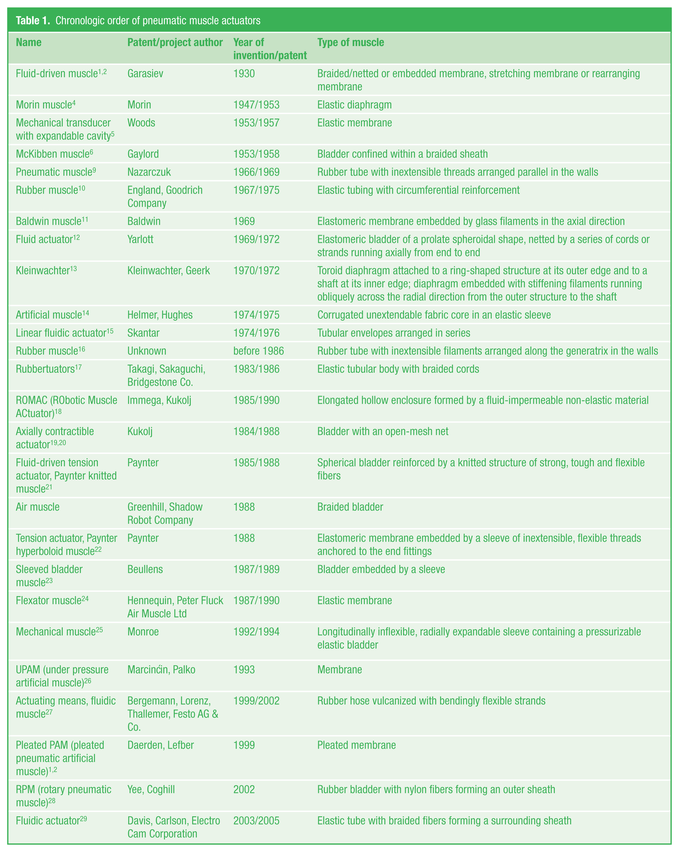
Chronologic order of pneumatic muscle actuators
There are two main types of pneumatic muscles: a rubber bladder constrained by a flexible mesh with predefined geometrical dimensions, weave angle and adequate flexibility, and a rubber tube vulcanized with the mesh. In both cases, the mesh, attached to both ends of the muscle actuator, acts as tendons. The force generated by the pneumatic muscle is dependent on the air pressure, nominal length, contraction ratio and material properties. When the air pressure rises, the muscle circumference increases while its length decreases, causing an increase in the muscle contraction. The resulting pulling force, acting in the axial direction, corresponds to the stresses in the flexible mesh. During the initial phase of the muscle contraction, a maximum force forms; yet, it declines gradually to zero at a maximum contraction, but only if the pressure is constant. By controlling pressure, we can control the pulling force and the contraction ratio of the pneumatic muscle actuator. Since a pressurized artificial muscle is highly non-linear, it is difficult to control. There have been many attempts to solve this problem. 30 It is required that a precise analytical model of a PAM be developed, hence the intensive research.
The basic model of Fluidic Muscle (MAS and DMSP) is presented in Hesse 31 and in advertising materials of Festo. However, this model concerns PAMs (McKibben and Shadow Air Muscle), and the characteristics determined on the basis thereof are significantly different from the characteristics of Festo catalog. The basic formula has been modified by Tondu and Lopez 32 through the correction coefficient k. PAM model takes into account the Young’s modulus presented in Davis et al. 33 Another model 34 concerned the addition of the function ε(p), of which the coefficients are determined by the method of least squares. Other papers35–37 concerned modeling by means of empirical or exponential formulas. In a latest paper, 38 modeling using software Modelica was presented, while in Aschemann and Schindele, 39 a comparison of three different feed-forward compensation strategies that counteract hysteresis effects was presented. New papers of authors40,41 referred to problems with heat transfer can be included in further studies. Other new papers primarily concerned the use of pneumatic muscles in the construction of robots, manipulators, artificial limbs and humanoid robots and design of the control systems of the pneumatic muscles. Most models of pneumatic muscles are based on the model in Tondu and Lopez. 32 The authors of this paper did not find such a modeling in other studies. The best solution is experimental determination of static and dynamic characteristics of pneumatic muscle. 37
II. Methods for Determining Static Characteristics of Pneumatic Muscles
A PAM operates like a natural skeletal muscle; therefore, its static characteristics are determined in the same way as those of a natural muscle. If the tension in the muscle remains constant (F = const), the contraction is called isotonic. If the tension increases while the muscle length remains the same (L = const), the contraction is called isometric. If, however, the tension rises and then remains the same as the muscle contracts without changing its length, then the contraction is known as auxotonic or secondary load-dependent isotonic. The method used for determining isotonic characteristics of a bladder-type PAM involves measuring the muscle length when the load is constant, and there are changes in internal pressure. Determining isometric characteristics requires controlling the internal pressure so that the contraction is constant while the load changes. The method for determining the isobaric characteristics corresponding to an auxotonic contraction consists of measuring the muscle length when the load changes and the internal pressure is constant (p = const).
It is important that static characteristics be calculated using relative contraction of the muscle, also known as the contraction ratio35,42–44
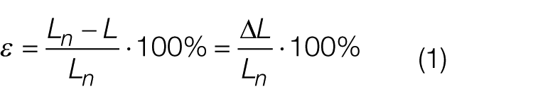
where Ln is the nominal length of the muscle, L is the a ctual length of the muscle and ΔL is the difference between the actual length and the nominal length.
While designing a machine or device with a pneumatic muscle, we need to know its permissible operating range, which is limited by the maximum permissible pulling force, the maximum contraction ratio, the maximum permissible internal pressure and the maximum permissible extension. Knowledge of its static characteristics is also essential. Depending on the purpose of the device, we consider isobaric, isotonic and isometric characteristics.
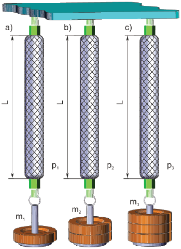
Static isobaric characteristics of the pneumatic muscle F(ε, p) represent the relationship between the pulling force and the contraction ratio at a constant internal pressure p = const. The principle of determination of isobaric characteristics (p = const) for a pneumatic muscle is presented in Figure 1 . The contraction ratio is measured while the internal pressure remains constant, with respect to the pulling force or the force generated by applying a mass load.
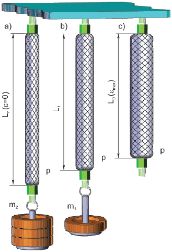
Method of determination of isobaric characteristics of a pneumatic muscle (p = const): (a) maximum pulling force F = Fmax at zero contraction ratio ε = 0, (b) intermediate state and (c) zero pulling force F = 0 at maximum contraction ratio ε = εmax
Static isotonic characteristics of a pneumatic muscle ε(p, F) represent the contraction ratio in the function of internal pressure at a constant tension (F = const) and a varying contraction ratio (ε = var). The characteristics are limited by the maximum permissible relative contraction and extension. The method of determination of isotonic characteristics (F = const) is illustrated in Figure 2 . The relative contraction ratio is measured at a constant load, with respect to the internal pressure.
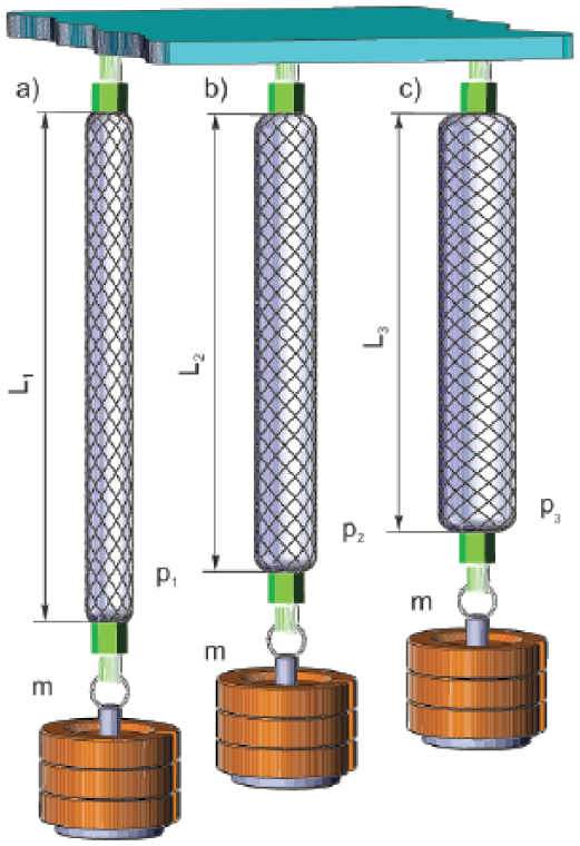
Method of determination of isotonic characteristics of the pneumatic muscle (F = const)
Static isometric characteristics of the pneumatic muscle ΔF(ε, p) represent the relationship between an increase in the pulling force and the internal pressure, determined at a constant contraction ratio (ε = const) and a varying tension (F = var). The method of determination of isometric characteristics (ε = const) is presented in Figure 3 . The change in the internal pressure is measured at a constant contraction ratio and a varying tension.
Method of determination of isometric characteristics of the pneumatic muscle (ε = const)
III. A Test Stand for Measuring Static Characteristics
The test stand was designed to experimentally determine the characteristics of the pneumatic muscles. The schematic diagram of the test stand is presented in Figure 4 , while its general view is shown in Figure 5 .
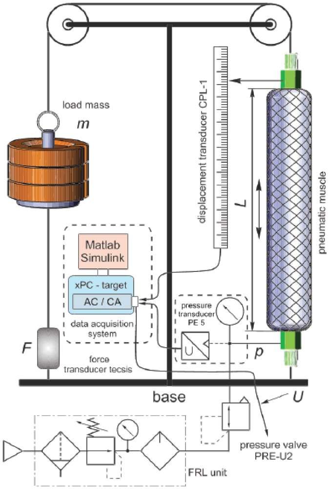
Schematic diagram of the test stand
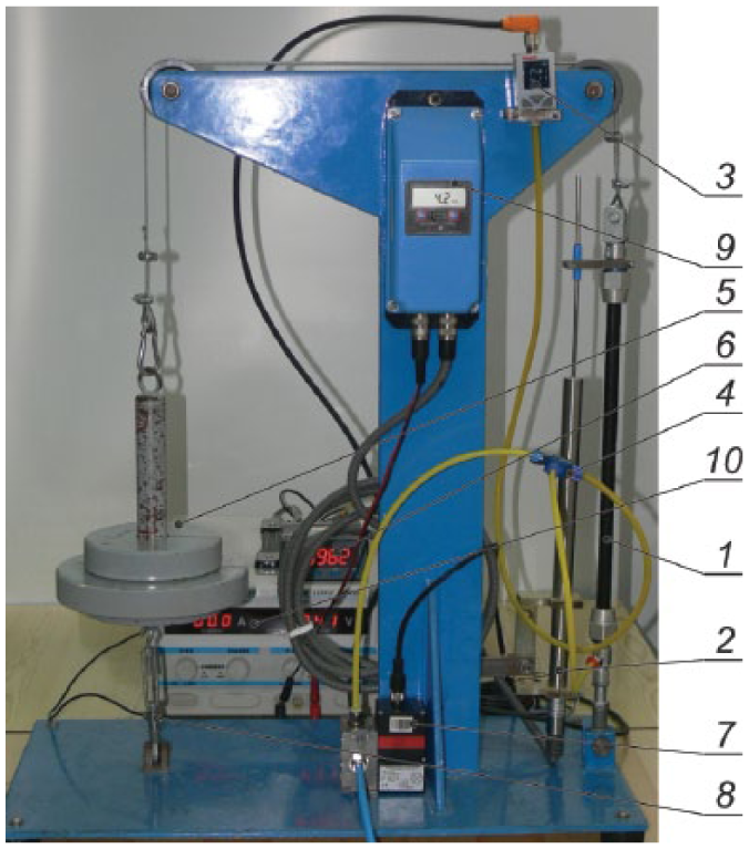
General view of the test stand for determining static characteristics of pneumatic muscles: 1—pneumatic muscle; 2—position sensor; 3—pressure sensor; 4—pneumatic tubes; 5—mass load; 6—electronic system of the force sensor; 7—proportional pressure valve; 8—pressure sensor; 9—electronic system of the displacement sensor; 10—laboratory power supply
The test stand consists of
A Festo MAS-10-300 Fluidic Muscle or a Shadow S30AM-S-1 Air Muscle—parameters are shown in Table 2 ;
A Hoerbiger PRE-U2 PS120100-080 piezo pilot controlled 3/2 way proportional pressure valve, electronic closed loop controlled by voltage 0–10 V, pressure range 1–6 bar, hysteresis <0.2%, linearity <0.5% and leakage ≤1.5 NL/min;
An Elektroserv-ZAP CPL-1 linear displacement sensor with a 4–20 mA analogue current, displacement range 100–280 mm, time constant 0.1–20 s and processing error ≤0.2% full scale output (FSO);
A Bosch PE5 pressure sensor with a 0–10 V analogue output, pressure range 0–10 bar, response time <5 ms and accuracy 0.1%;
A Tecsis force sensor with a 0–10 V analogue output, force ±2000 N and accuracy 0.3%;
A mass load;
An SMC air preparation unit combined with an air filter-regulator-lubricator (FRL), nominal filtration rating 5 µm and maximum operating pressure 1.0 MPa;
24 VDC power supply;
MATLAB/Simulink xPC Target data acquisition system (software) and Speedgoat Education Real-Time Target Machine (hardware).
Comparison of parameters of two pneumatic muscles
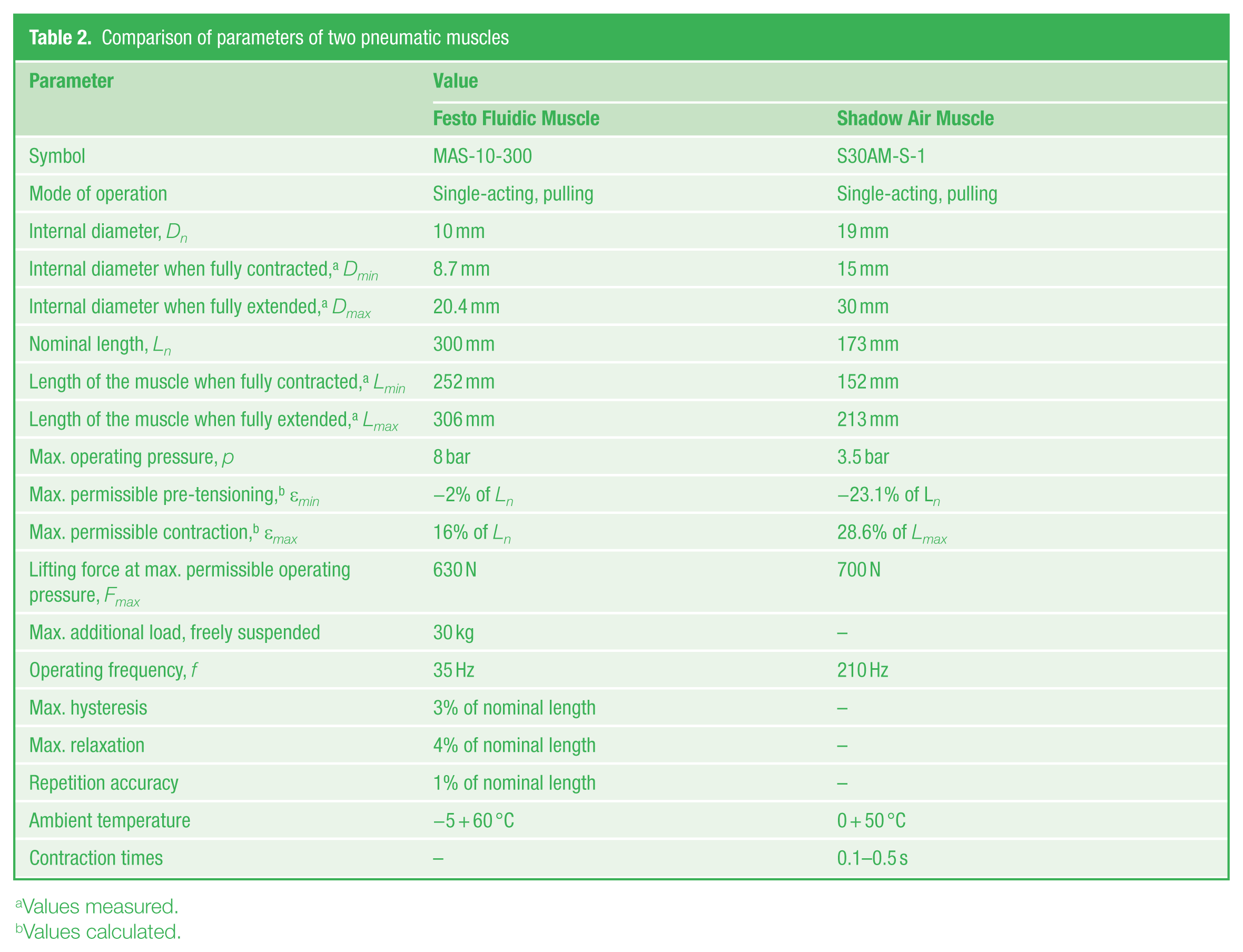
Values measured.
Values calculated.
The pneumatic muscle was connected to the base at one end and to a mass load suspended on a steel wire passing through a pulley at the other. The contraction of the pneumatic muscle was measured using a transformer position transducer, linked in parallel with the pneumatic muscle. The muscle was controlled by means of a precision piezoelectric pressure servovalve, whereas the internal pressure was measured with a piezoelectric pressure transducer. The values of the internal pressure and the contraction were read out directly by sensors of electronic devices, and the data were acquired by the data acquisition system.45–48 Complete, fully assembled and tested Education Real-Time Target Machine included ruggedized chassis, industrial mainboard with two peripheral component interconnect (PCI) slots (whereas one is equipped with an I/O module providing the provided analogue and digital I/O connectivity), on-board Gigabit Ethernet controller for host–target communication, Intel Core 2 Duo 2.23 GHz CPU, 2048 MB RAM (Random Access Memory), 1024 MB industrial-grade CompactFlash device, 32 single-ended or 16 differential analogue input (software selectable), 4 analogue output (single-ended), 8 digital transistor-transistor logic (TTL) input and 8 digital TTL output channels (16-bit), I/O cable, terminal board, digital visual interface (DVI-I) to video graphics array (VGA) adapter and universal power supply.
The testing facility was equipped also with a force transducer, fitted between the mass load and the base, which enabled direct measurement of the pulling force of the muscle at zero contraction (ε = 0).
IV. Experimental Data
The tests were performed on the special test stand using the methods described in Section II aimed at determining the isotonic characteristics ε(p, F) at F = const, the isometric characteristics ΔF(p, ε) at ε = const and the isobaric characteristics F(ε, p) at p = const. The static characteristics were established experimentally for two pneumatic muscles: a Festo Fluidic Muscle MAS and a Shadow Air Muscle.
Figure 6 shows dimensions of the muscle under normal conditions ( Figure 6(b) ), when fully extended ( Figure 6(a) ) and when fully contracted ( Figure 6(c) ).
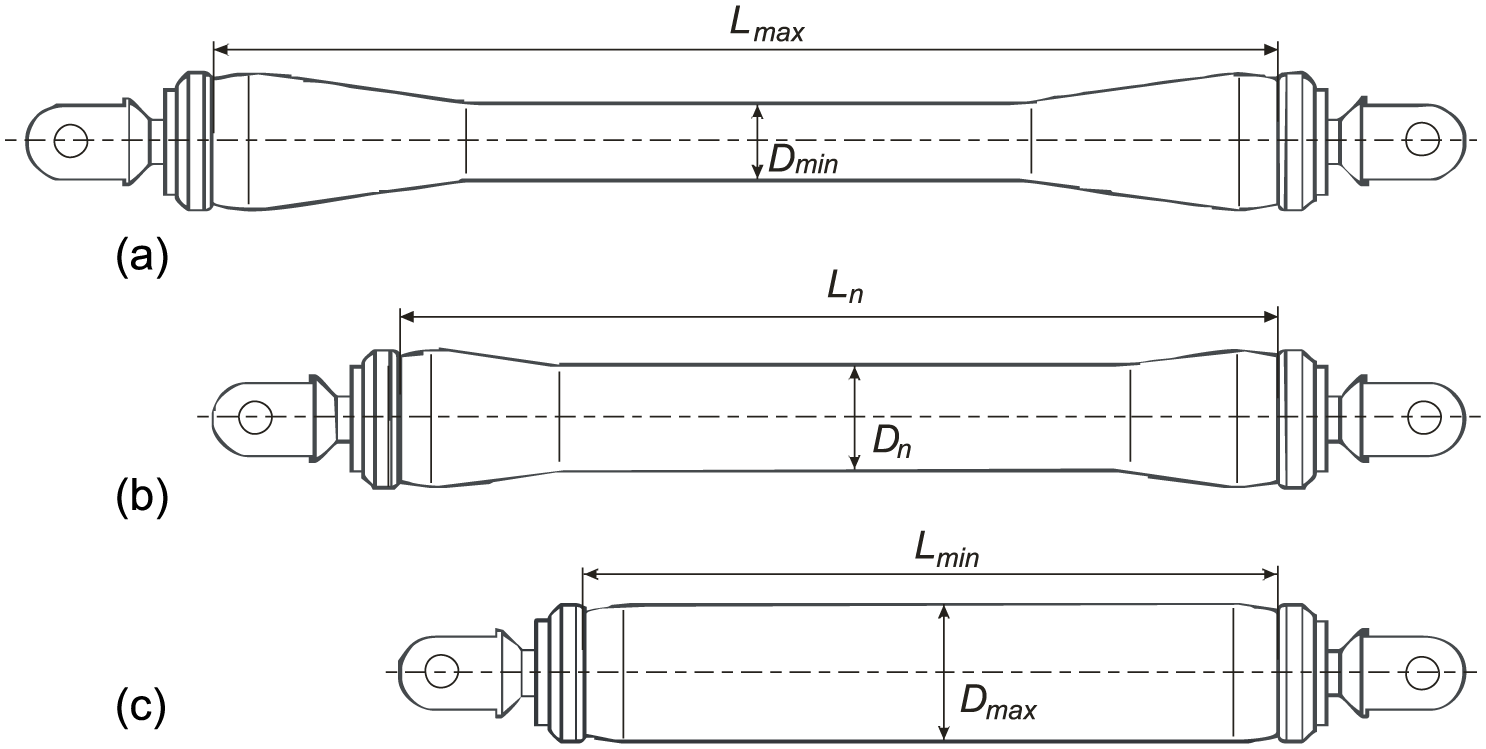
Dimensions of the muscle: (a) when fully extended, (b) under normal conditions and (c) when fully contracted
Table 2 shows the parameters of the pneumatic muscles. The experimental tests were conducted for two pneumatic muscles differing in design, functional properties and operating conditions. Formula (1) was assessed as insufficient to calculate the relative contraction. The relative contraction was thus defined using Formula (2), while the minimum and maximum contractions were determined according to Formulae (3) and (4), respectively
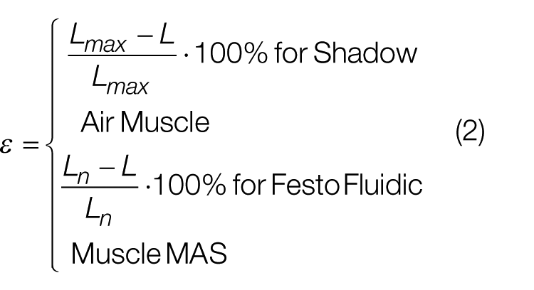
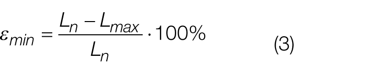
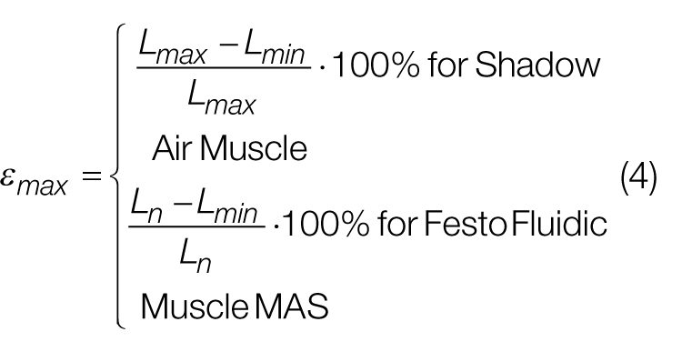
where L is the actual length of the muscle, Ln is the nominal length of the muscle, Lmax is the length of the muscle when fully extended and Lmin is the length of the muscle when fully contracted.
Figure 7 shows the isotonic characteristics; Figure 8 illustrates the isometric characteristics, while Figure 9 presents the isobaric characteristics of the Festo Fluidic Muscle MAS and the Shadow Air Muscle.
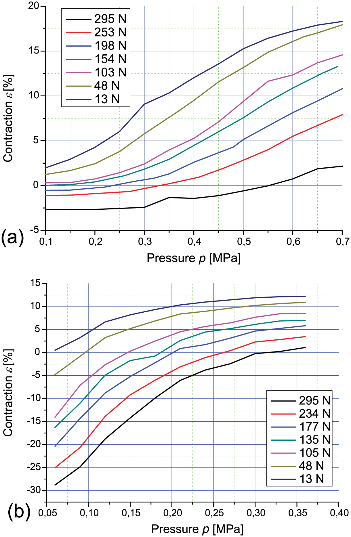
Isotonic characteristics ε(p): (a) Festo Fluidic Muscle MAS and (b) Shadow Air Muscle
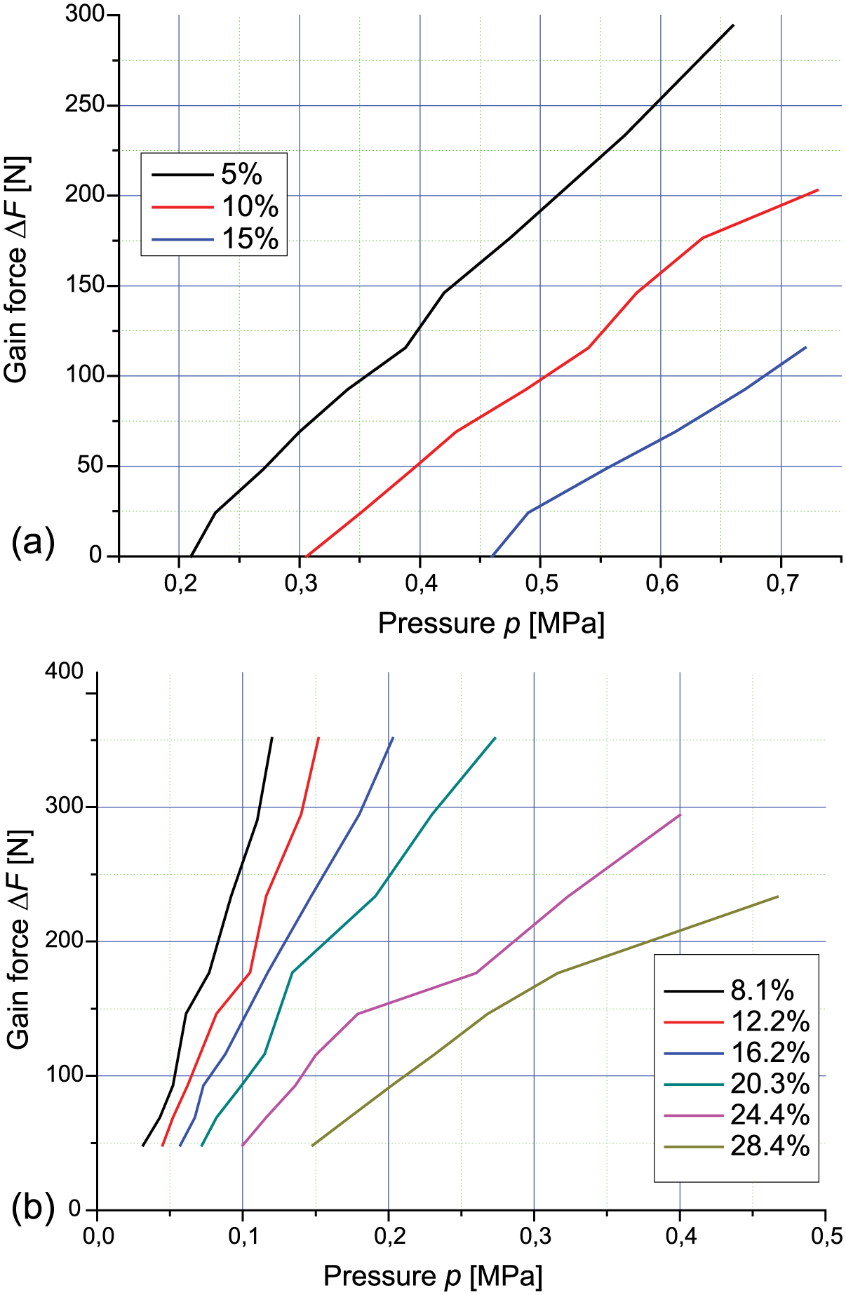
Isometric characteristics F(p): (a) Festo Fluidic Muscle MAS and (b) Shadow Air Muscle
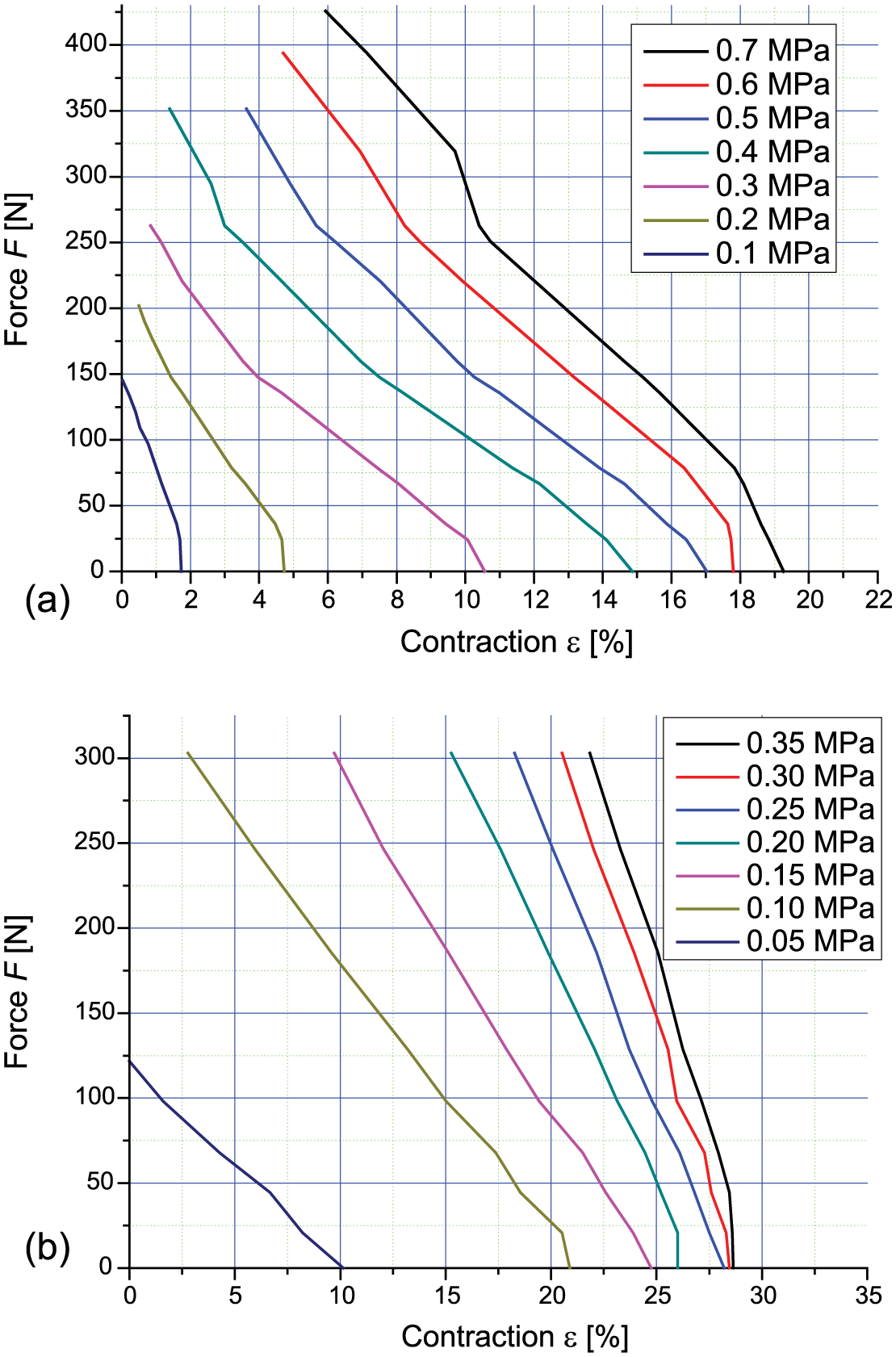
Isobaric characteristics F(h): (a) Festo Fluidic Muscle MAS and (b) Shadow Air Muscle
V. An Analytical Method for Determining the Static Characteristics of the Pneumatic Muscles
There have been many mathematical models describing the pulling force and the contraction ratio of pneumatic muscles.1,2,6,17,30–37,43,44,49–52 From a practical point of view, the most interesting are the characteristics showing the relationship between the pulling force and the contraction ratio F(ε, p) at a constant internal pressure, p = const. The pulling force of the pneumatic muscle was calculated using the modified formula 32
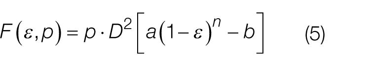
where ε is the contraction ratio, F is the pulling force, D is the muscle diameter, a is the muscle constant, b is the muscle constant and n is the power.
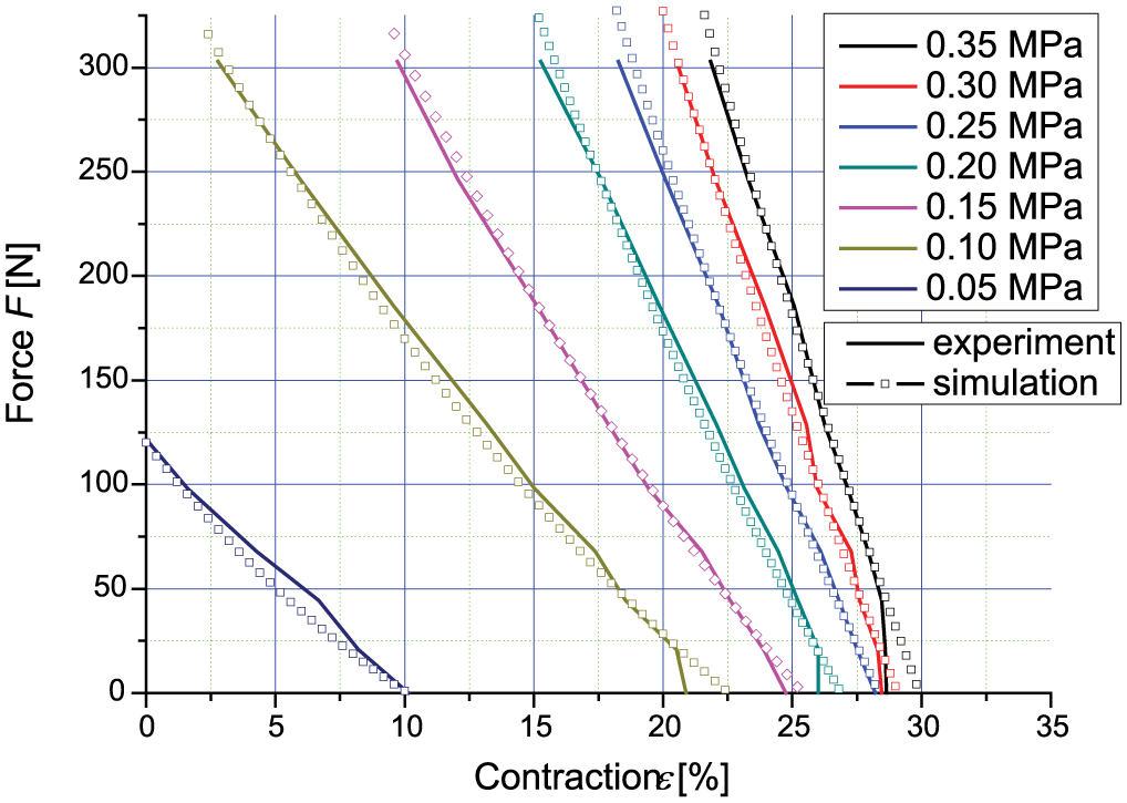
The experimental data obtained for the Festo Fluidic Muscle MAS were used to determine the muscle constants: a = 17, b = 8 and n = 3.2/35; then, simulations were conducted to establish the isobaric characteristics F(ε, p) ( Figure 10 ).
Isobaric characteristics F(ε, p) of the Festo Fluidic Muscle at a = 17, b = 8, n = 3.2/35
Assuming that n is a function of internal pressure, n(p) was calculated as
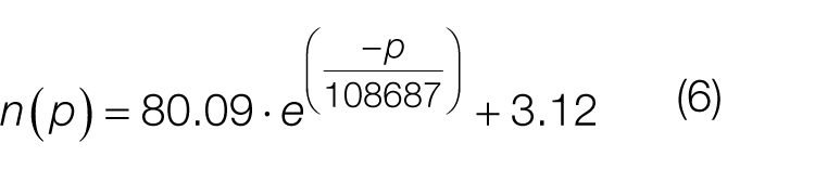
After substituting Formula (6) into (5), the formula for the muscle contraction was obtained
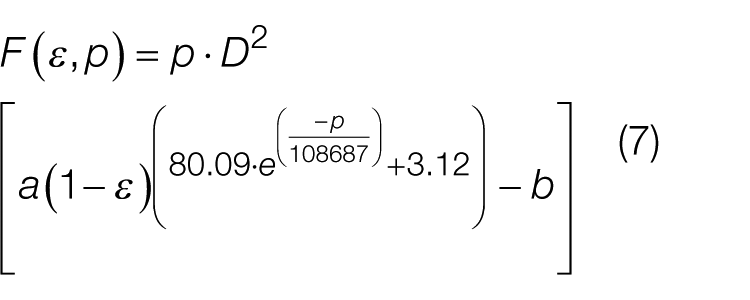
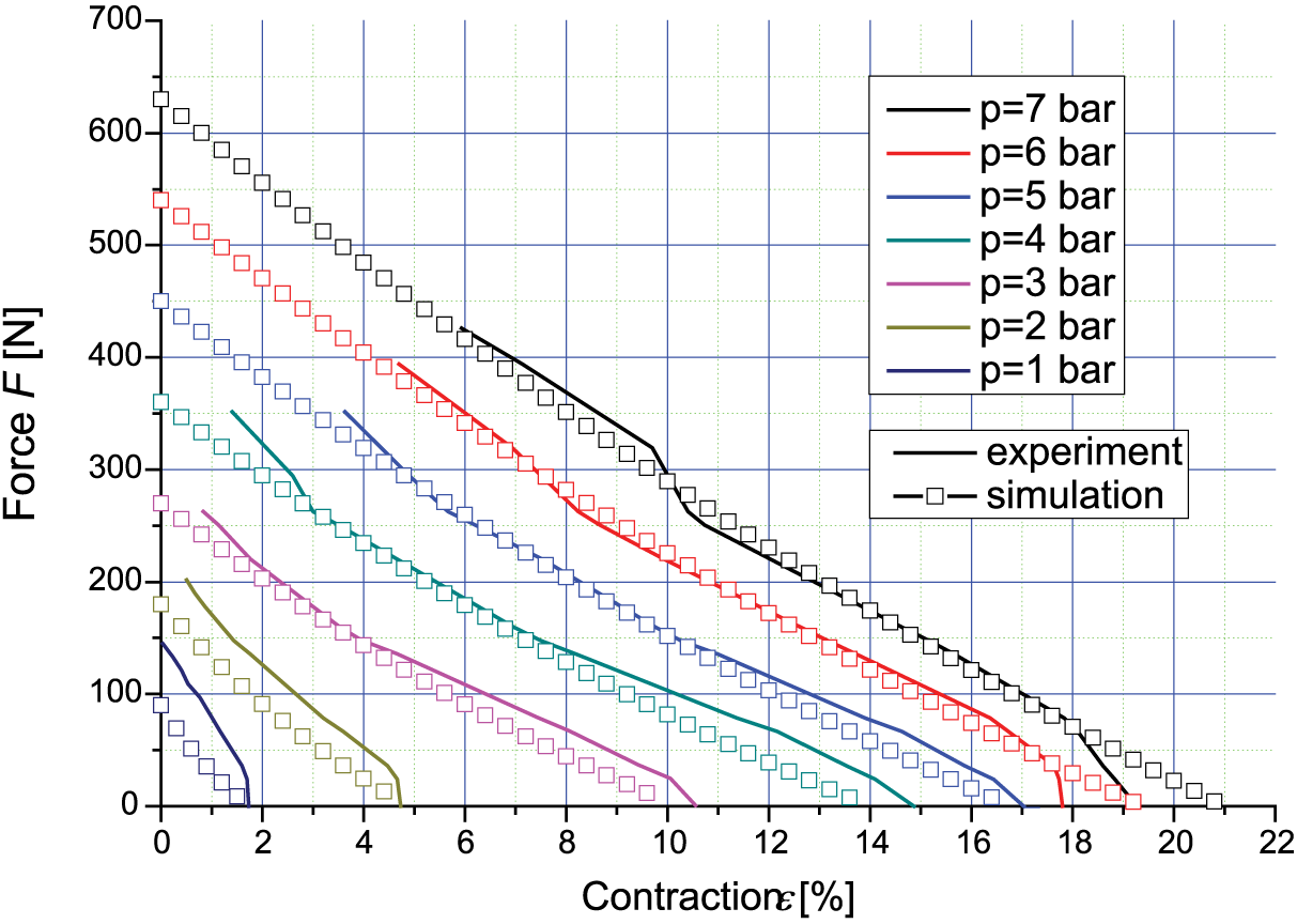
Formula (7) was used to carry out simulations and determine the isobaric characteristics of the pneumatic muscle F(ε, p) ( Figure 11 ).
Isobaric characteristics F(ε, p) of the Festo Fluidic Muscle at a = 17, b = 8 and n(p)
Similarly, a was considered to be a function of internal pressure, and a(p) was determined as
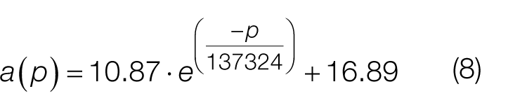
Substituting Formula (8) into (7), the final formula for the muscle contraction was obtained
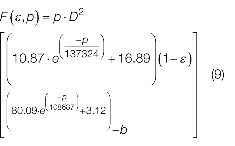
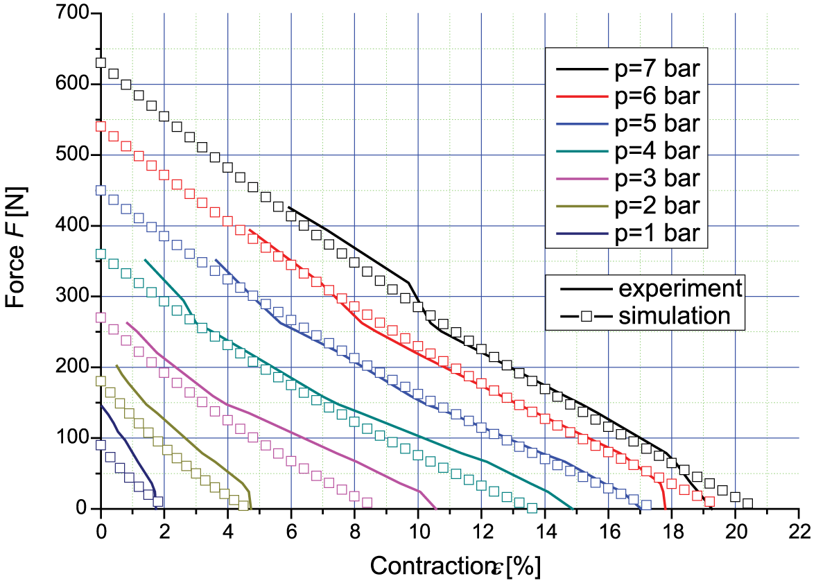
Formula (9) was employed to perform simulations and then determine the isobaric characteristics of the pneumatic muscle F(ε, p) ( Figure 12 ). The experimental data nearly coincided with the simulation results.
Isobaric characteristics F(ε, p) of the Festo Fluidic Muscle for a(p), n(p) and b = 8
The same procedure was used for the Shadow Air Muscle. The equation obtained for F(ε, p) is
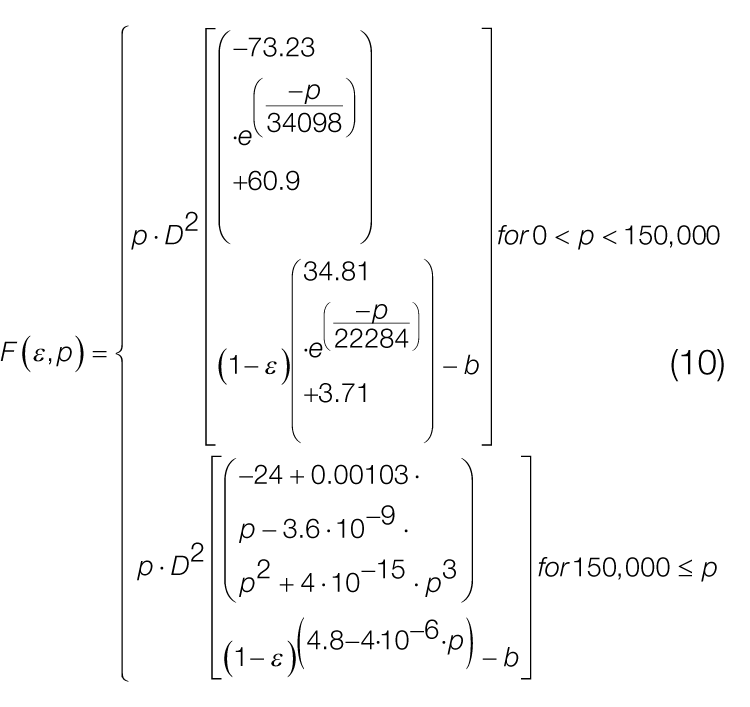
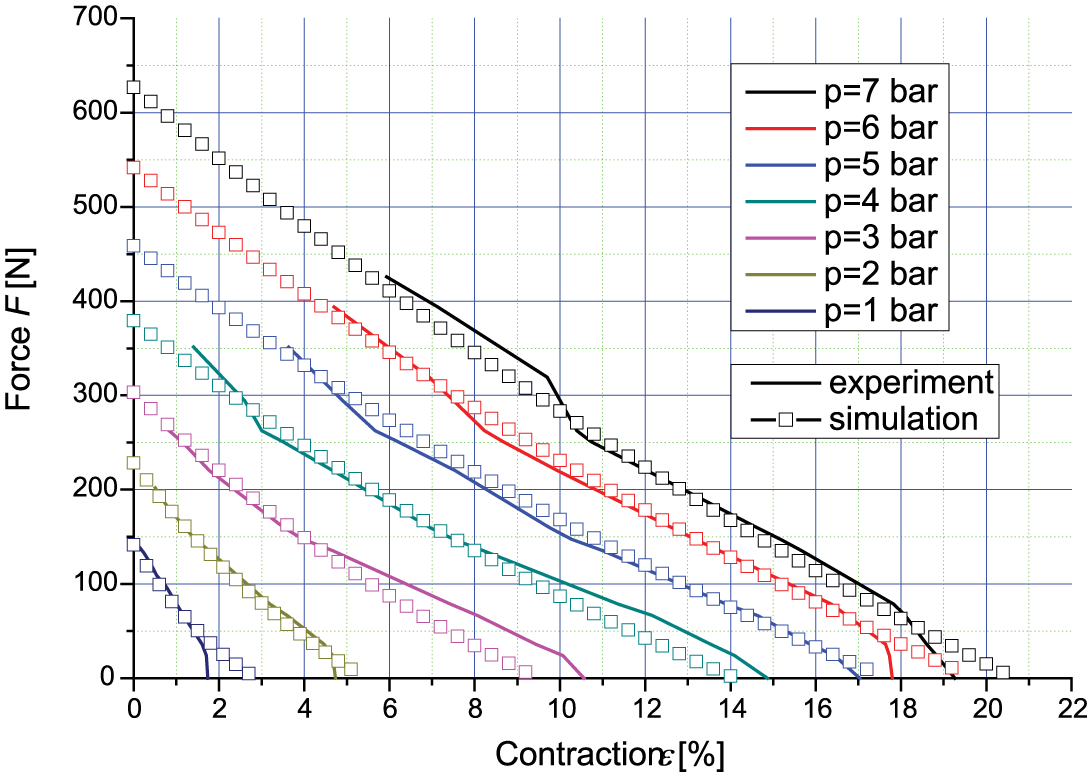
Formula (10) was applied in the simulations to calculate the isobaric characteristics F(ε, p) of the Shadow Air Muscle ( Figure 13 ).
Isobaric characteristics F(ε, p) of the Shadow Air Muscle for a(p), n(p), b = 10
All muscle constants were calculated using Simulink Design Optimization of MATLAB software. Simulink Design Optimization provides interactive tools and functions for estimating and tuning Simulink model parameters using numerical optimization. 53 An interactive tool lets automatically estimate model parameters from test data to increase model accuracy. User can preprocess test data, select model parameters to estimate, start an optimization and validate estimation results.
VI. Conclusion
The variety of pneumatic muscles presented chronologically in the introduction suggests that there is a need for intensive research on this type of drive. The knowledge of the static characteristics of pneumatic muscles is vital to design machines and devices with a muscle drive. In this paper, we have described a test stand and methods for determining static—isobaric, isotonic and isometric—characteristics of pneumatic muscles. The stand was used to test two types of commercially available pneumatic muscles: a Fluidic Muscle MAS by Festo Corporation and an Air Muscle by Shadow Robot Company. The experimental data were used to derive equations describing the static characteristics of the muscles. These were employed to perform simulations and then a comparative analysis of the experimental and simulation results for both muscles.
Compared with piston actuators, pneumatic muscles have different force characteristics, depending on the internal pressure, the nominal length, the contraction ratio and the muscle material properties. These elastic, single-acting cylinders pulling the load in the axial direction may be used as pneumatic springs. Pneumatic muscles behave like natural ones; they can be used in mobile, anthropomorphic, humanoid robots and artificial limbs. Pneumatic muscles generate a considerable axial force relative to the mass and cross-sectional area. Their motion is smooth, and there is no step effect. They are deformed in the radial direction; there is no stick–slip phenomenon inside, and they exhibit natural damping properties. Pneumatic muscles can be applied in many different devices, which requires combining them into kinematic structures: antagonistic, serial, parallel and hybrid. Antagonistic pairs consist of two muscles: agonistic and antagonistic. Pneumatic muscles fitted as drive elements can also be used in parallel manipulators and robots and automated production systems, where high motion dynamics is required at a small stroke.
The pneumatic muscles analyzed here vary in design, functional properties and operating conditions. The Festo Fluidic Muscle MAS consists of a vulcanized rubber tube constrained by a braided mesh sleeve, whereas the Shadow Air Muscle is a rubber bladder surrounded by a braided mesh sleeve. The muscles tested differ in the static characteristics, which implies their different applications. The Festo Fluidic Muscle MAS is a rigid, not-to-be-extended muscle. It cannot be stretched, otherwise the weave will break; it can only be contracted. The Shadow Air Muscle has a relatively loose weave, which makes it easy to contract and stretch.
Footnotes
Funding
The author(s) received no financial support for the research, authorship and/or publication of this article.