
Abstract
Photovoltaic power generation is a promising alternative source of energy and has many advantages than the other alternative energy sources like wind, solar, ocean, biomass, geothermal, and so on. In photovoltaic power generation, multilevel inverters play a vital role in power conversion. The three different topologies, diode-clamped (neutral-point clamped) inverter, capacitor-clamped (flying capacitor) inverter, and cascaded H-bridge multilevel inverter, are widely used in these multilevel inverters. Among the three topologies, cascaded H-bridge multilevel inverter is more suitable for photovoltaic applications since each photovoltaic array can act as a separate direct current source for each H-bridge module. In this paper, a single-phase cascaded H-bridge five-level inverter for grid-connected photovoltaic system using proportional–integral controller is presented. Sinusoidal pulse width modulation technique was used for eliminating the harmonic distortion. The cascaded control strategy enables tracking of the maximum power point of distinct photovoltaic strings and allows independent control of the direct current-link voltages. The performance of single-phase cascaded H-bridge five-level inverter with respect to harmonic content and number of switches is simulated using MATLAB/Simulink. A hardware prototype is developed to verify the performance of the developed system. The results of hardware are compared with the simulation results. The proposed system offers improved performance over conventional two-level inverters.
I. Introduction
In recent years, the demand for clean and green energy has required high-quality output power with low switching losses. It is also seen the soft switching technology develop, showing that the demand further increases by improving efficiency. This trend is expected to continue in coming years because the energy produced by renewable sources is expected to satisfy 20% and 50% of the total needs in 2020 and 2050, respectively. It is also witnessed that among these renewable energy sources, solar photovoltaic (PV) energy is found to be a promising energy.
An important consequence of this situation is a change in the electric power system from the present one, consisting of a relatively low number of very high-power alternating current (AC) generators, to a distributed one, characterized by an extremely large number of small- and medium-power direct current (DC) and AC generators supplied by renewable energy sources connected to the grid through electronic power converters, the latter adapting the produced energy to grid specifications.
This new scenario introduces many technical, economic, and political challenges because it is changing the way in which the electrical energy resources (generation, transmission, and distribution networks) are designed and managed. From the technical viewpoint, the use of electronic power converters introduces new and challenging issues, including increased topological complexity, additional power losses, and electromagnetic interferences, thus reducing the overall quality of service, efficiency, and network stability.
Franquelo et al. 1 introduced the pulse width modulation (PWM) multilevel inverter as an effective alternative to current inverter topologies and provided an introduction of the modeling techniques and the most common modulation strategies. Lai and Peng 2 have described three recently developed multilevel voltage source converters and the techniques to balance the voltage between different levels in multilevel converters. Rodriguez et al. 3 have described the most relevant control and modulation methods developed for this family of converters: multilevel sinusoidal pulse width modulation (SPWM), multilevel selective harmonic elimination, and space-vector modulation. Tolbert et al. 4 have experimentally demonstrated that traditional two-level high-frequency PWM inverters for motor drives have several problems associated with their high-frequency switching and two different multilevel topologies are identified for use as a converter for electric drives. Rodriguez et al. 5 have introduced the PWM regenerative rectifiers with reduced input harmonics and improved power factor. In early stages, multilevel active rectifiers were employed mainly in high-voltage, high-power industrial and traction applications because they distribute the applied voltage among a number of cascaded power devices, thus overcoming their voltage limits and allowing the elimination of output transformers in medium- to high-voltage systems. Since their output voltage is a modulated staircase, the fact that they outperform two-level PWM inverters in terms of total harmonic distortion (THD), without the use of bulky expensive and dissipative passive filters, has been demonstrated in Cecati et al.6,7 Multilevel inverters in the field of renewable energies, including PV generators, have been described in Kjaer et al. 8 and Calais and Agelidis. 9 Calais et al. 10 and Gonzalez et al. 11 have developed unipolar SPWM full-bridge with transformer-less grid-connected inverter, a lot of depth researches, where new freewheeling paths are constructed to separate the photovoltaic array (PVA) from the grid in the freewheeling period.
Ertl et al. 12 have proposed a novel multicell DC–AC converter for applications in renewable energy systems. Alonso et al. 13 have introduced a new control method and proportional PWM of the cascaded H-bridge multilevel converter for grid-connected PV systems, and this control makes each H-bridge module supply different power levels, allowing, therefore, for each module an independent maximum power point tracking of the corresponding PVA. Walker and Sernia 14 have proposed an alternative topology of nonisolated per-panel DC–DC converters connected in series to create a high-voltage string connected to a simplified DC–AC inverter, and buck, boost, buck–boost, and Cu’k converters are considered as possible DC–DC converters that can be cascaded. Rahiman et al. 15 have developed a 15-level cascaded H-bridge configuration; equal DC voltages are selected for each unit, with step modulation and fundamental frequency switching which reduced conduction loss and switching loss. Kang et al. 16 have developed multilevel PWM inverters suitable for the use of stand-alone PV power grid-connected inverters for PV modules. Alepuz et al. 17 have described a three-level inverter that can be used to interface distributed DC energy sources with a main AC grid or as an interface to a motor drive. Ozdemir et al. 18 have proposed a five-level DMLI fundamental frequency switching strategy for three-phase stand-alone PV systems by selecting the switching angles such that the lower order harmonics are eliminated. Besides being able to maximize the power obtained from the PVAs, the multilevel converter usually presents the advantages of reducing the device voltage stress, being more efficient, and generating a lower output, that is, a voltage harmonic distortion. Among the following three main families of multilevel converters, diode-clamped, capacitor-clamped, and cascaded H-bridge, the latter is usually considered in the literature for PV applications.19,20
Fortunato et al. 21 have proposed an improved maximum power point tracking with better performance to solve a fast changing irradiation problem. Shanthi and Natarajan 22 have proposed multilevel inverter control strategies implemented in real time using field-programmable gate array (FPGA) for linear and non-linear loads. Yang et al. 23 have introduced H∞ controller with explicit robustness in terms of grid-impedance variations to incorporate the desired tracking performance and stability margin. Josh et al. 24 have proposed multilevel inverter in the field of renewable energies, which reduces output filter dimensions and influences the perturbations caused by cloud darkening or seasonal variations. Mei et al. 25 have proposed an improved phase disposition pulse width modulation (PDPWM) for a modular multilevel inverter which is used for PV grid connection to achieve dynamic capacitor voltage balance without the help of an extra compensation signal.
It is clear from the above literature works that many researchers are addressing their efforts in proposing new inverter topologies or in modifying the existing ones, aiming at improving the quality of the energy available at the inverter terminals. Among the available multilevel inverter topologies, cascaded H-bridge multilevel inverter is proven to be the best for its high power-handling capacity and reliability due to its modular topology and constitutes a promising alternative that can be extended to allow a transformer-less connection to the grid.
The cascaded H-bridge multilevel inverter requires separate DC source, and it is a drawback when a single DC source is available, but it becomes a very attractive feature in the case of PV systems because solar cells can be assembled in a number of separate generators. The CHB-MLI supports different PWM techniques like SPWM, selective harmonic elimination pulse width modulation (SHEPWM), and optimized harmonic stepped waveform (OHSW).
A typical single-phase two-level inverter adopts full-bridge configuration using approximate sinusoidal modulation technique as the power circuits. The output voltage has the following three values: zero, positive (+VDC), and negative (−VDC) supply DC voltage (assuming that VDC is the supply voltage). The harmonic components of the output voltage are determined by the carrier frequency and switching functions. Therefore, their harmonic reduction is limited to a certain degree.
To overcome this limitation, this paper presents a five-level inverter whose output voltage can be represented in five levels. As the number of output levels increases, the harmonic content can be reduced. The SPWM switching strategy and cascaded inverter structure are employed in this work. This inverter topology uses two reference signals, instead of one reference signal, to generate PWM signals for the switches.
In this paper, a single-phase cascaded H-bridge five-level inverter for grid-connected PV system using proportional–integral (PI) controller is proposed. The results confirm the effectiveness of the proposed controller. The experimental results are presented to confirm the simulation results.
This paper has been arranged as follows. After the introduction in Section I, Section II gives an outline of cascaded H-bridge multilevel inverter topology. SPWM is presented in Section III. Power balance between the H-bridge inverters is described in Section IV. Sections V and VI show the simulation and experimental results that validate the proper operation of the inverter. Conclusion and final remarks are made in Section VII.
II. Cascaded H-Bridge Five-Level Inverter Topology
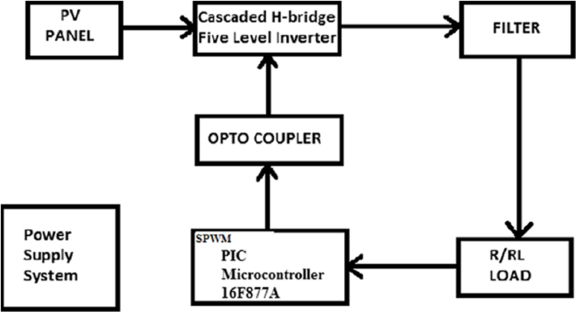
The block diagram of the proposed cascaded H-bridge inverter topology with SPWM is shown in Figure 1 . This system consists of several PV modules, DC–DC power converter, a multilevel DC–AC power inverter, and an RL load. The PV modules’ arrangements are considered with multi-string technology. Each string of the PVA is connected to a DC–DC boost converter with a maximum power point tracking. As the irradiance level is inconsistent throughout the day, the amount of power generated by the PV modules is always changing with weather conditions. The Perturb and Observe algorithm is used to extract maximum power from the PVA. The DC power from the PVA is boosted using the DC–DC boost converter with DC bus capacitors. The output of these converters is the DC power supply of the multilevel DC–AC power converter. The output of five-level inverter is AC voltage which is connected to grid system utility feeder through filtering inductor. The injected current must be sinusoidal with low harmonic distortion. The power factor is also maintained at near unity. The load is considered as resistive and inductive. The above proposed SPWM with the closed-loop control is implemented using MATLAB software.
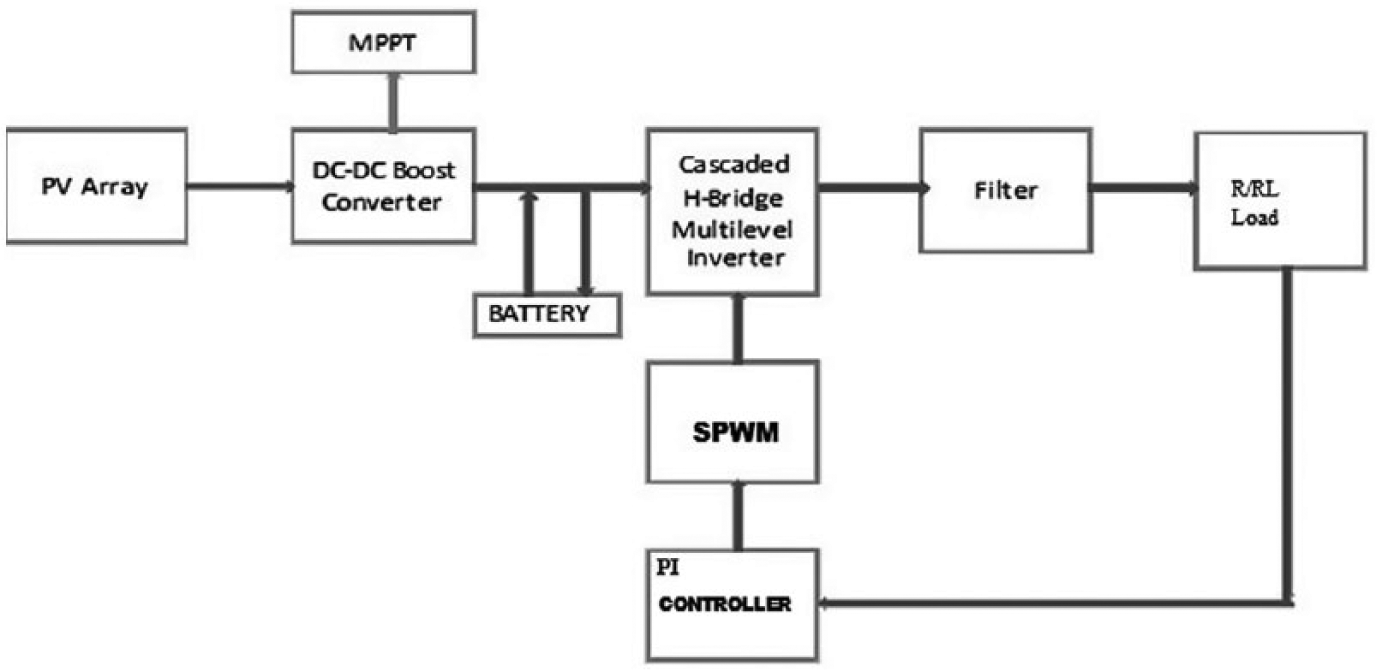
Block diagram of cascaded H-bridge inverter topology
A schematic diagram of cascaded H-bridge inverter topology of grid-connected PV system is shown in Figure 2 . The cascaded multilevel inverter topology consists of n H-bridge inverters connected in series. Each DC link is fed by a short string of PV panels. By considering cells with the same DC-link voltage, the inverter can synthesize an output voltage vHT with n levels. This high-quality voltage waveform enables the reduction of the harmonics in the generated current, reducing the filtering effort at the input. This topology can inject to the grid sinusoidal input currents with unity power factor, even under conditions of unequal solar radiation of the string of PV cells.
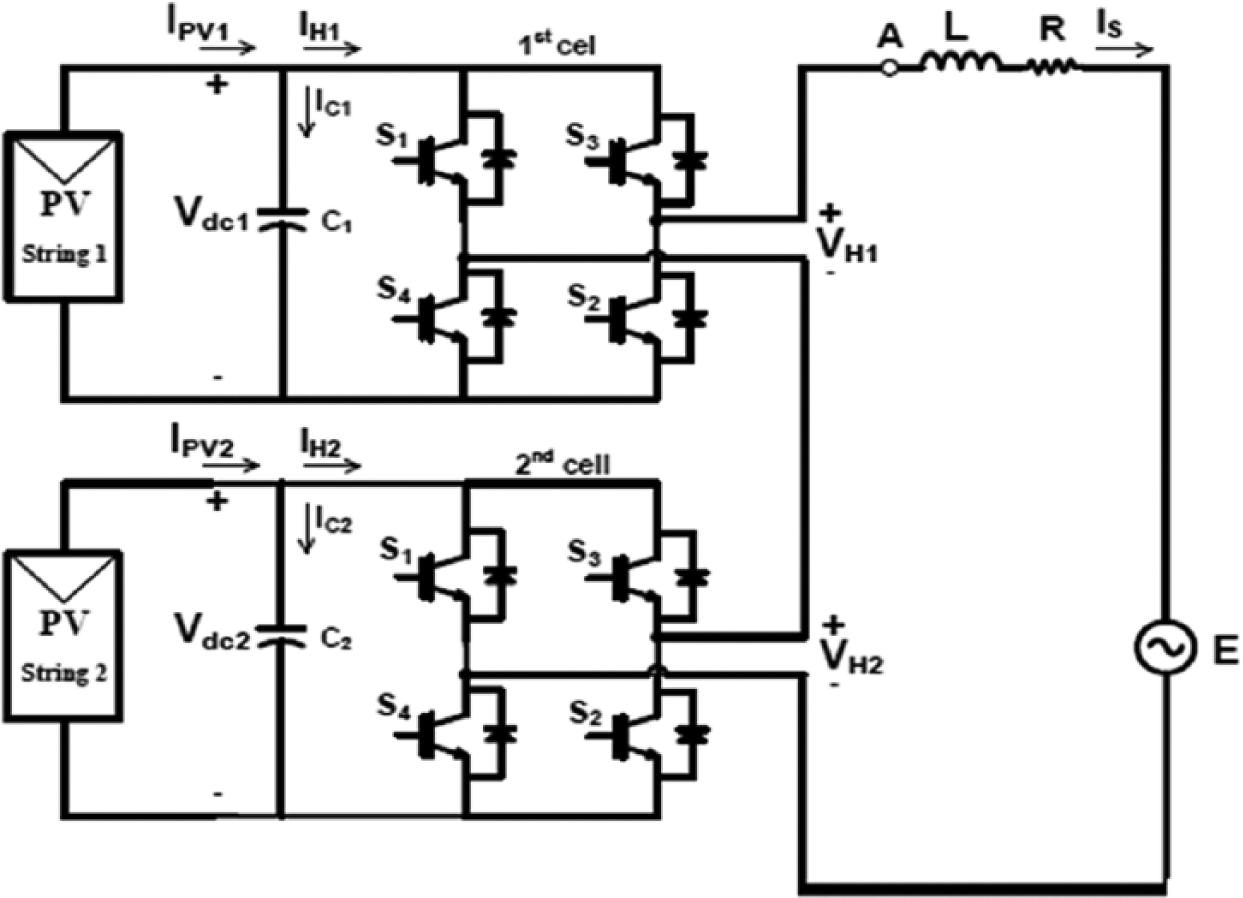
Cascaded H-bridge inverter topology of grid-connected photovoltaic system
The proposed inverter level used for this system is cascaded H-bridge five-level inverter. Two identical inverter modules are connected in series to form a single-phase five-level inverter. All modules are fed by DC voltage sources of the same magnitude. The output voltage has five voltage levels from −2 VDC to +2 VDC. The AC outputs of each of the different full-bridge inverter levels are connected in series such that the synthesized voltage waveform is the sum of the inverter outputs. The number of output phase voltage levels m in a cascaded inverter is defined by m = 2 s + 1, where s is the number of separate DC sources. The cascaded multilevel inverter is connected to the grid through an L filter, which is used to reduce the switching harmonics. There is also a local load connected in parallel. PV power is delivered to the load/grid according to the system operation conditions.
III. SPWM
PWM technique is extensively used for eliminating harmful low-order harmonics in inverters. In PWM control, the inverter switches are turned ON and OFF several times during a half cycle and output voltage is controlled by varying the pulse width. Several modulation strategies have been developed for multilevel inverters. The most commonly used is the SPWM technique.
In SPWM, instead of maintaining the width of all pulses the same as in the case of multiple PWM, the width of each is varied in proportion to the amplitude of a sine wave evaluated at the same pulse. The distortion is reduced significantly compared to multiple PWM. The gating pulses are shown in Figure 3 .
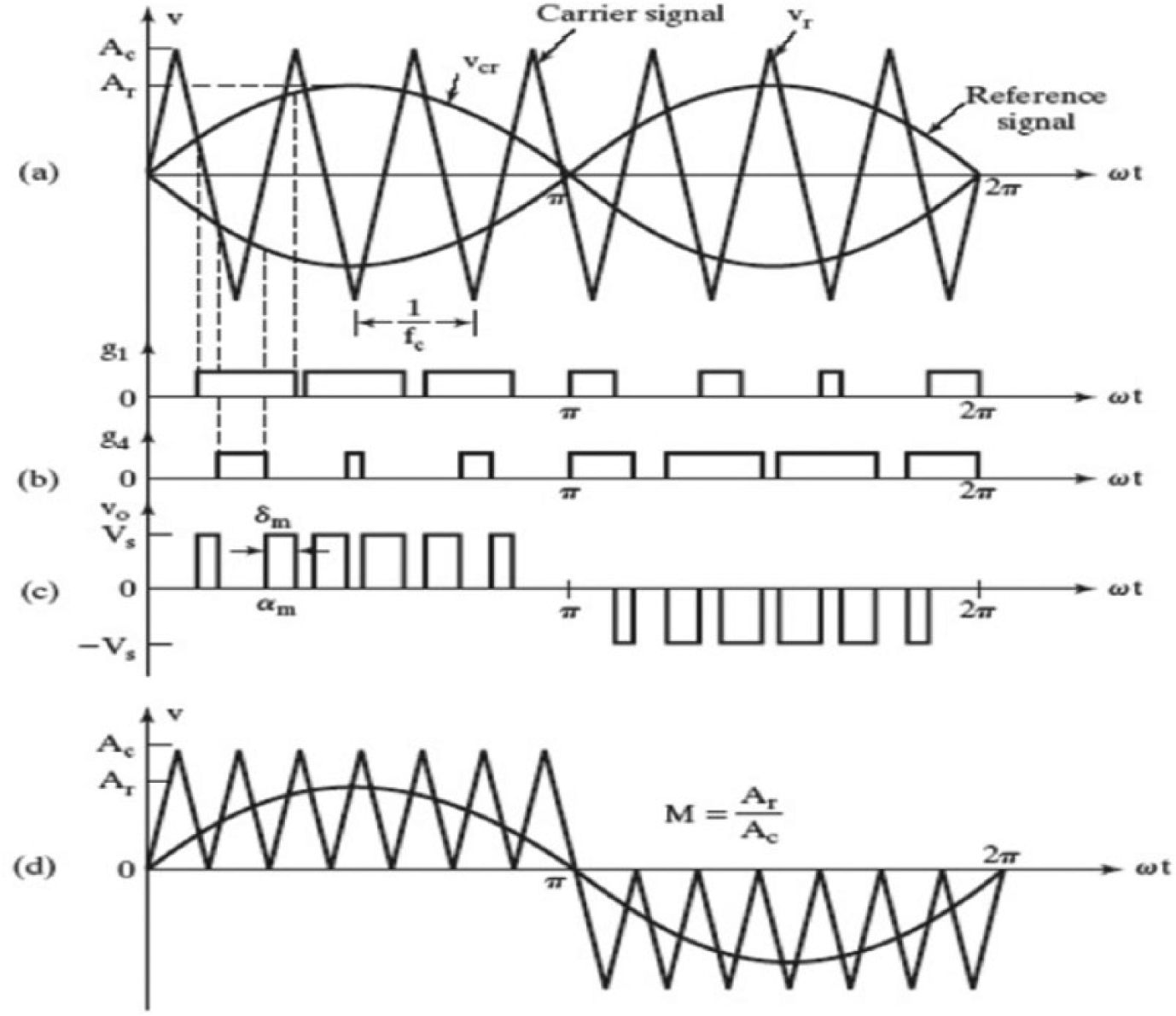
Sinusoidal pulse width modulation
IV. Power Balance between the H-Bridge Inverters
The power balance between the two H-bridge inverters depends on the DC-link voltages and the individual modulation signals. To evaluate the steady-state power balance in the cells of a cascaded inverter, the cells have been replaced by voltage sources with values v1 and v2 that are equal to the root mean square (rms) values of the fundamental harmonic of the voltages. Moreover, to have a stable operation, it is necessary to ensure that, for a total amount of active power supplied to the two-cell cascaded H-bridge inverter, both cell loads are between the maximum and minimum allowed.
V. Simulation Results
A simulation is carried out in MATLAB/Simulink software for a five-level cascaded H-bridge inverter with isolated DC sources. The elements and the parameters considered for simulation are presented in Table 1 for the cascaded H-bridge five-level inverter topology.
Parameters of the cascaded H-bridge inverter
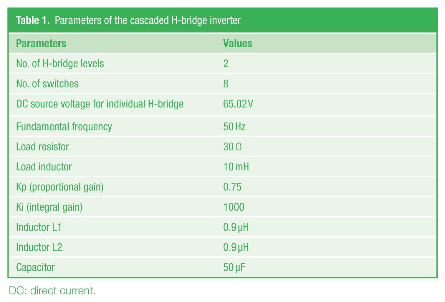
DC: direct current.
The simulation model of grid-connected PV system is shown in Figure 4 and the PV system with maximum power point tracking (MPPT) is shown in Figure 5 . The Simulink model consists of two H-bridges whose nominal DC voltage is considered to be 65.02 V, a DC boost converter working as MPPT, and a PWM inverter that connects the system to the grid, and the five-level stepped output voltage is obtained and the harmonics are reduced. Also, it consists of PWM generator block which has parameters such as amplitude, pulse width period, and phase delay which are used to determine the shape of the output. Therefore, the efficiency of the inverter is increased. The inverter must perform reliably and efficiently to supply a wide range of AC loads with the voltage and required power quality necessary for reliable and efficient load and system performance. The advantages of the system are high-power, high-voltage capacity; low harmonics; and low switching loss. The output voltage and output current have five levels. It can be achieved using the SPWM technique. The output five-level inverter fundamental frequency is 50 Hz. The loads are connected across the cascaded H-bridge five-level inverter.
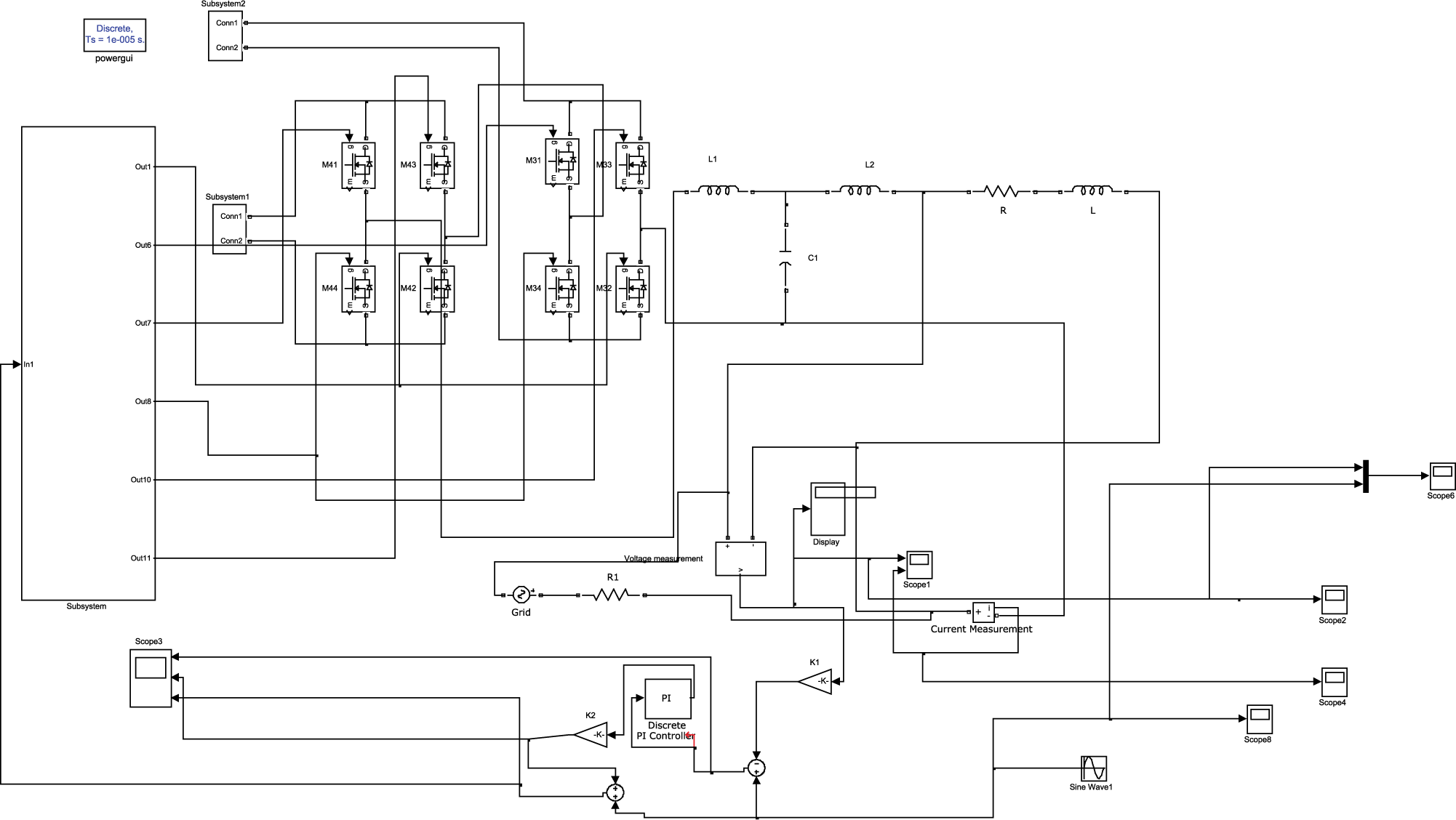
Simulink model of the grid-connected photovoltaic system
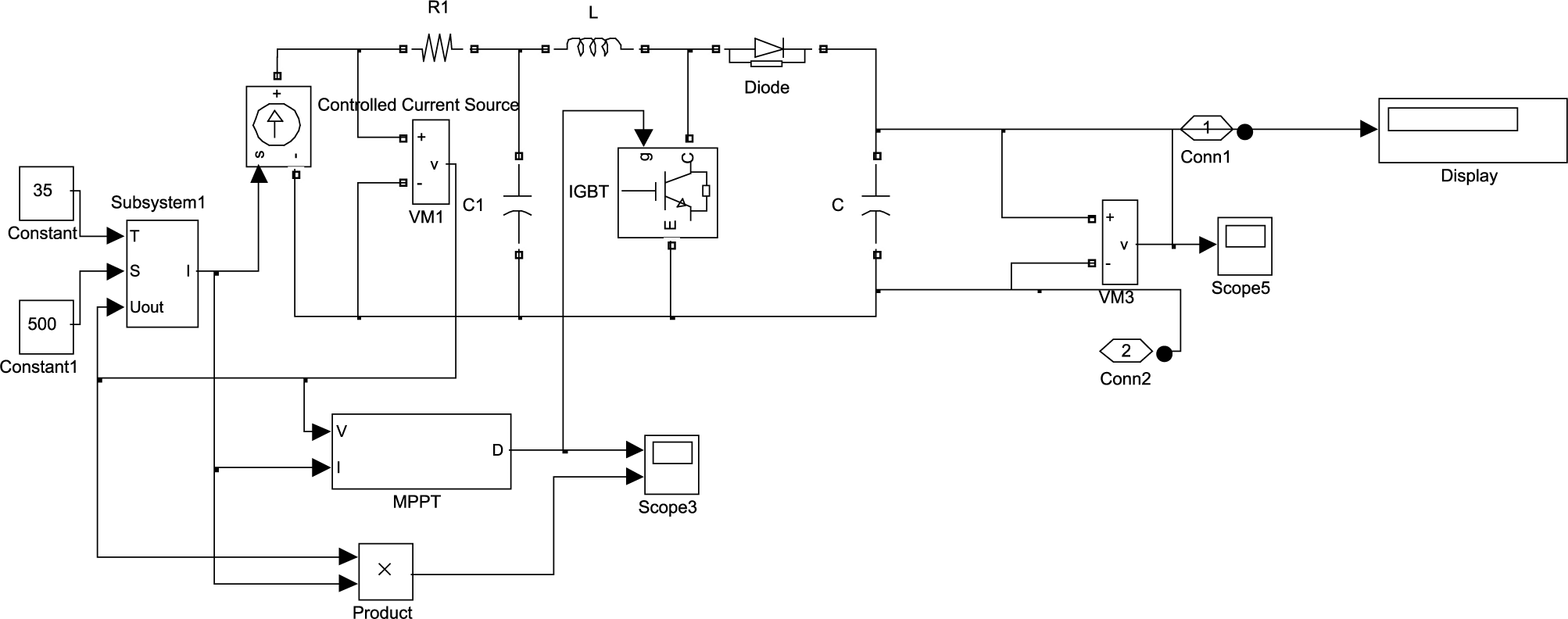
Simulink model of PV system with MPPT
The response of the MLI with SPWM is satisfactory, and the load voltage and load current waveforms are shown in Figure 6 . The THD waveforms for voltage and current are shown in Figures 7 and 8 , respectively. It is observed from the results that the THD for voltage is 18.01% and current is 15.05%. When the temperature of a cell decreases, the voltage of the corresponding cell increases, and when the cell temperature increases, the corresponding cell voltage decreases in order to extract the maximum power from the connected PVA.
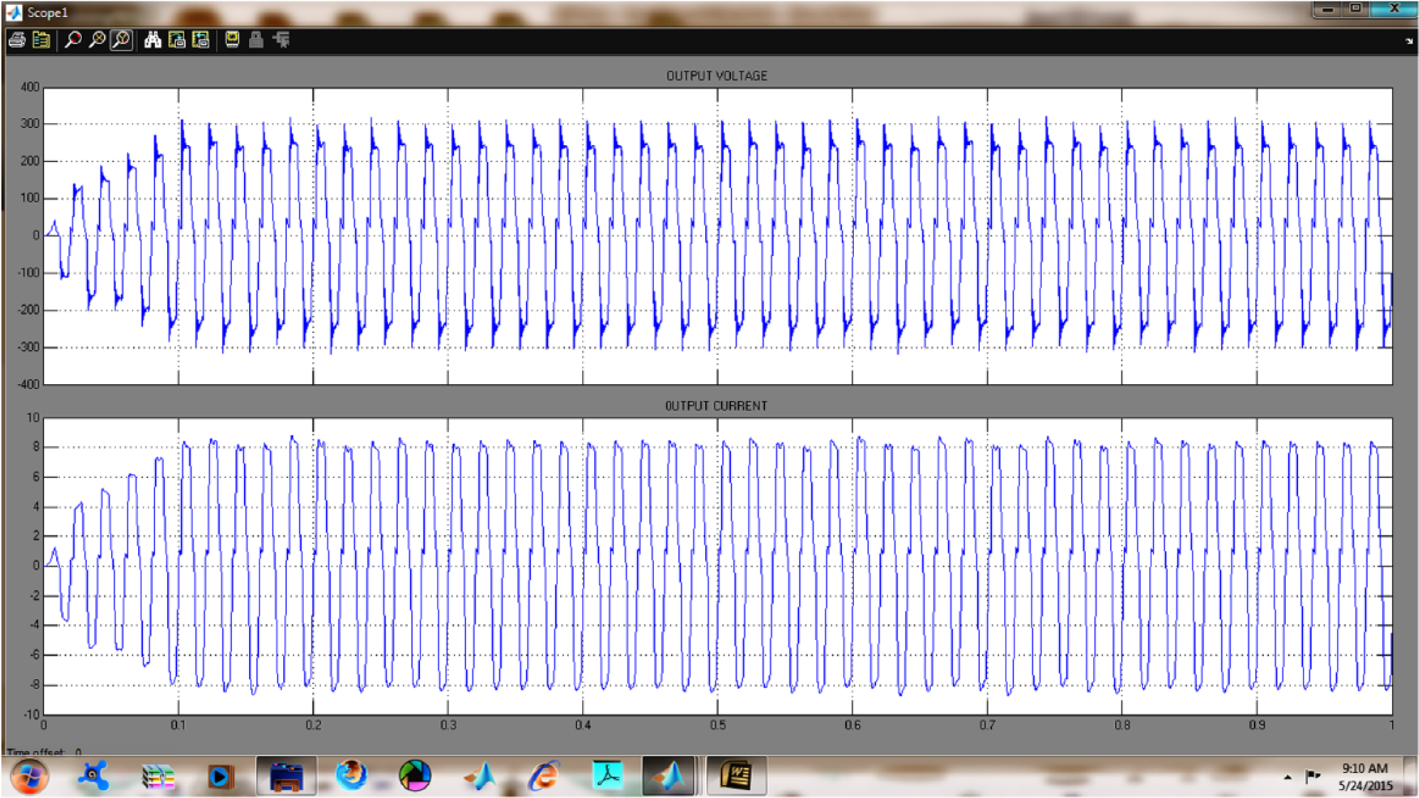
Load voltage and load current waveforms
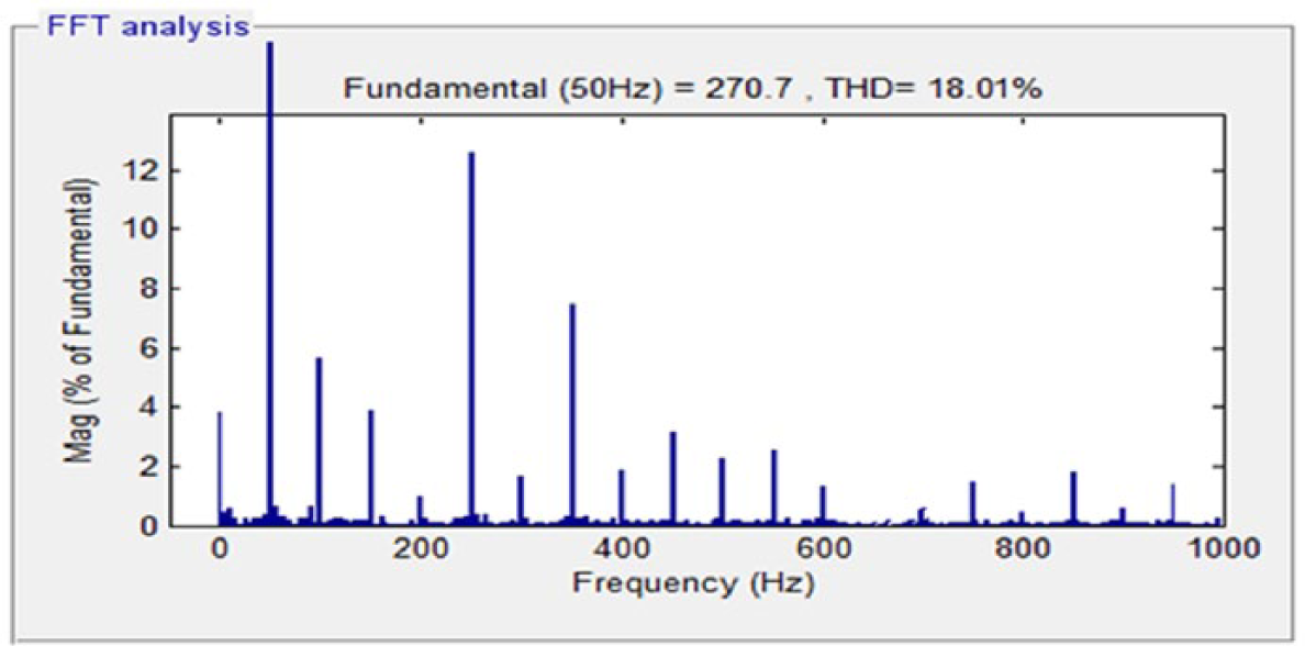
Voltage THD
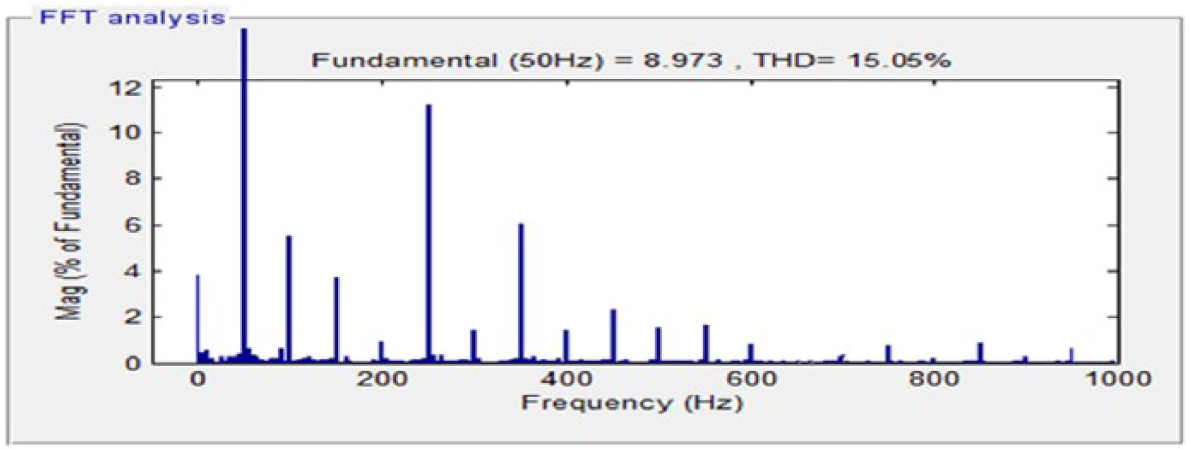
Current THD
VI. Experimental Results
The experimental block diagram of the proposed cascaded H-bridge inverter topology with SHEPWM is shown in Figure 9 . This block diagram consists of a multilevel DC–AC power inverter, optocoupler, PIC microcontroller, filter, and a load. The isolated DC power sources are connected to the cascaded H-bridge inverter. The output of the five-level inverter is AC voltage which is connected to load through filter. The load is considered as resistive and inductive.
Experimental block diagram
A single-phase 100 W hardware prototype five-level inverter as shown in Figure 10 is built. It consists of two full-bridge inverters that are connected in a series form. The inverter uses 8 A, 500 V metal–oxide–semiconductor field-effect transistors (MOSFETs) as the switching devices, and the DC source voltage of each H-bridge inverter from the PV panel is constant and is selected to be 34.8 V. Also, the frequency of the output is assumed to be 50 Hz. Six transformers (0–24 V, 2 A) are used to power up the individual H-bridge inverters. Three transformers (6–0–6 V, 500 mA) are used to power up the optocouplers. The real-time implementation for chosen inverter using PIC microcontroller 16F877A is carried out in this work. SPWM generation and also the control strategies for the chosen inverter are developed using MATLAB software. Furthermore, the DC link of each H-bridge is connected to an array of three series-connected panels, whose parameters are listed in Table 2 . The other principal parameters of the prototype are given in Table 3 . In this experiment, the average voltage of each cell is around 85 V, and the maximum power is extracted from the PV strings. The proposed controller also provides a rapid and accurate tracking of the MPP for PV strings without an additional DC–DC converter. The elimination of three intermediate DC–DC converters and independent control of the PV strings improve the system efficiency when compared to the conventional systems.
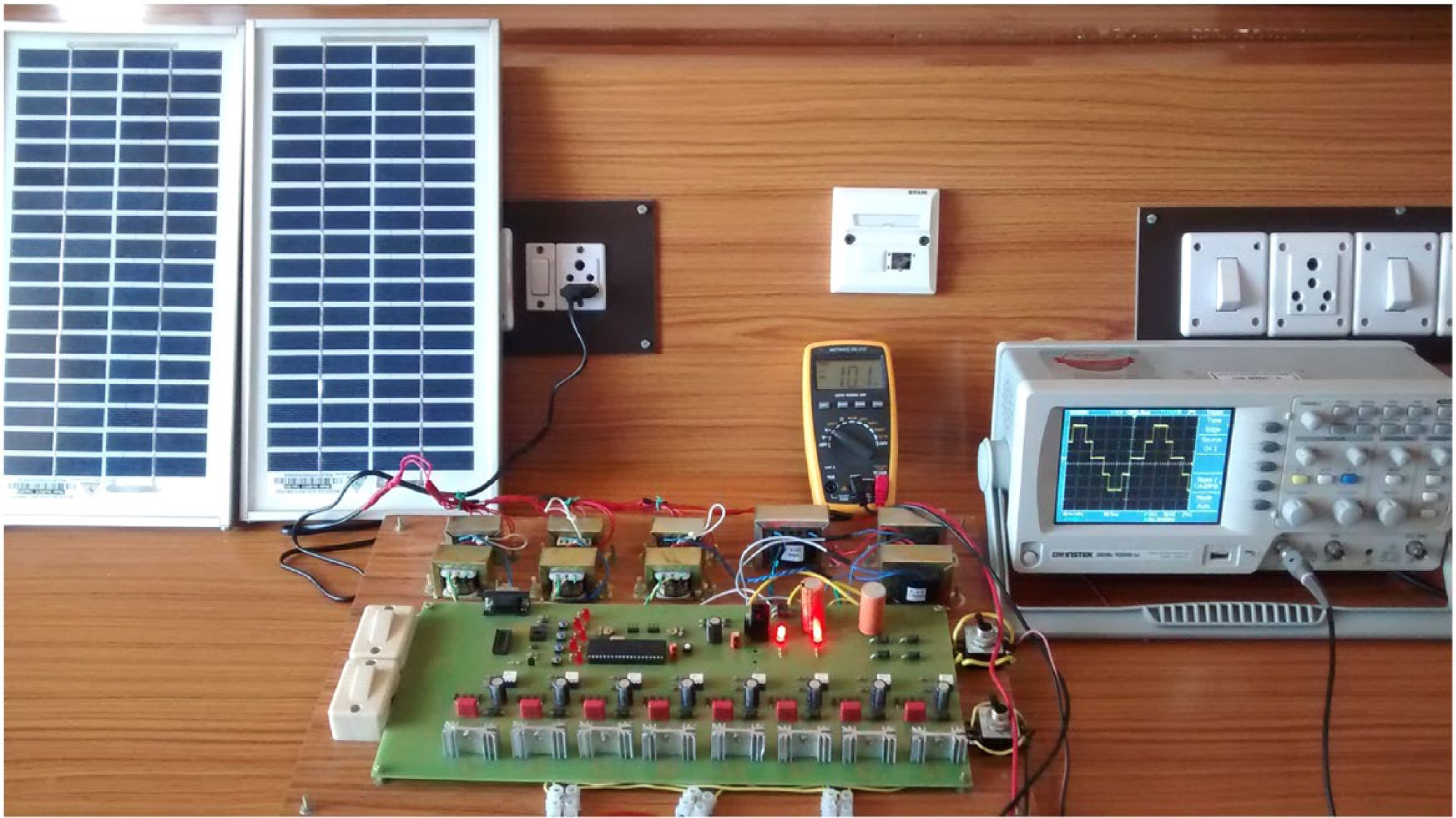
Structure of the experimental prototype
Parameters of the solar panels
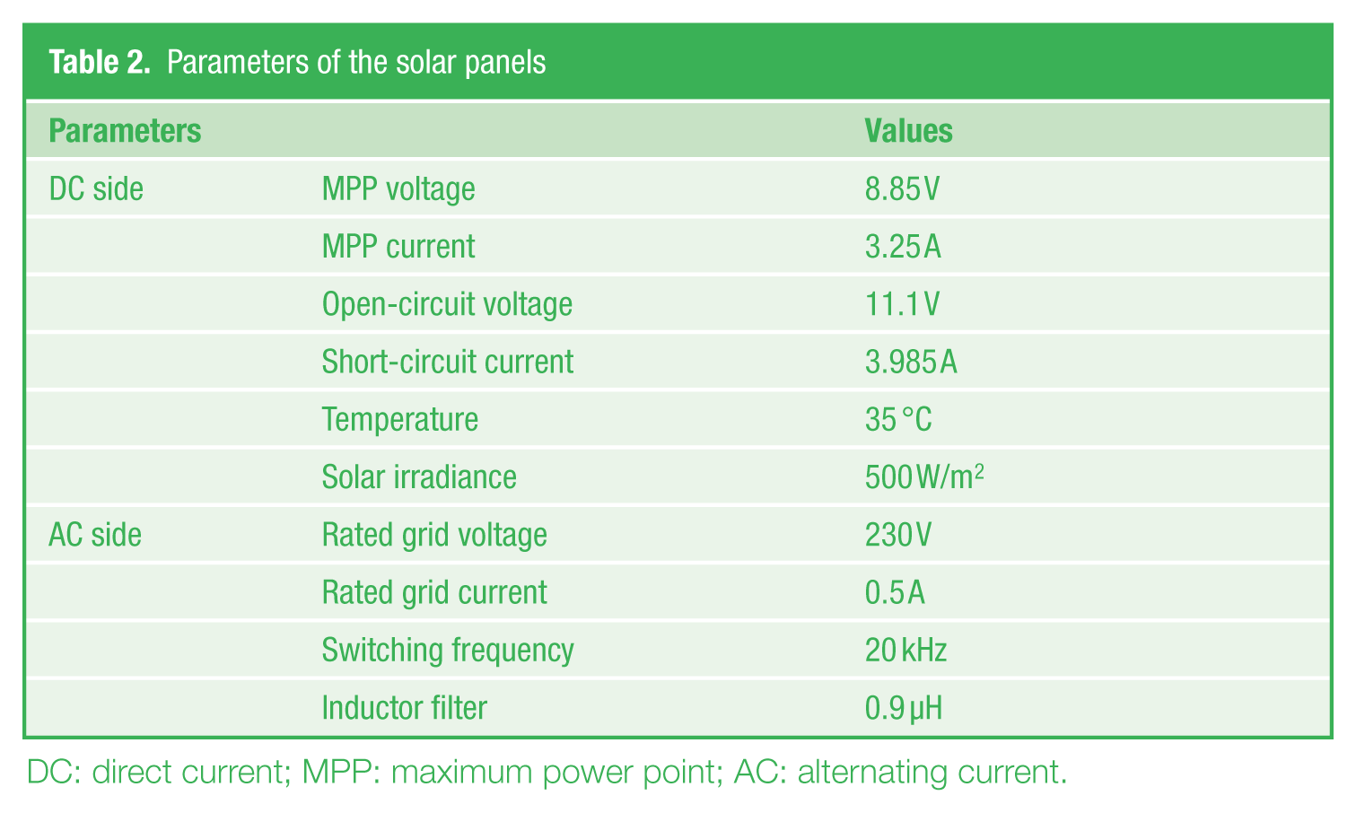
DC: direct current; MPP: maximum power point; AC: alternating current.
Experimental prototype specifications
MOSFET: metal–oxide–semiconductor field-effect transistor; DC: direct current.
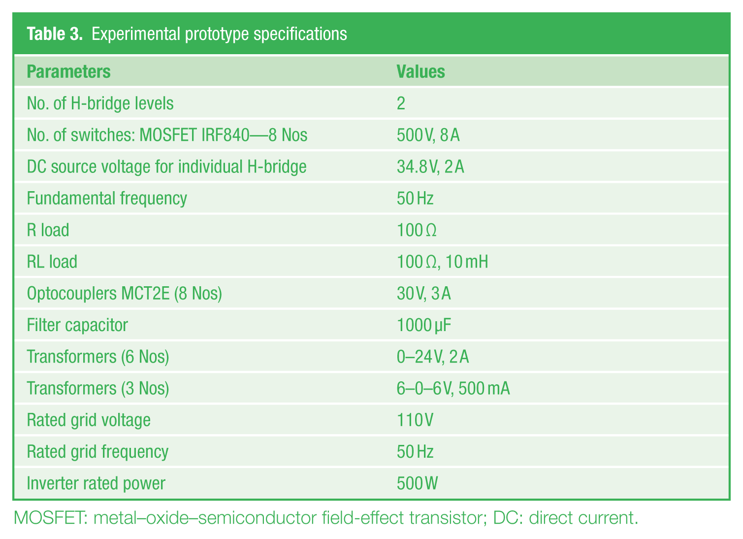
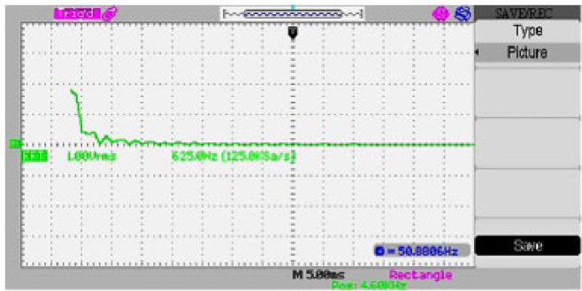
Figures 11 and 12 show the harmonic spectrum of the five-level and three-level inverter output voltage, respectively. Figures 13 and 14 show the output voltage waveform of the five-level and three-level inverter, respectively. The resulting PF is close to 0.98 and the current THD is nearer to the IEEE-519 constraints. The measured grid side voltage is 67 V for the first cell and 65 V for the second cell, whereas the voltage of each PV string is close to 85 V.
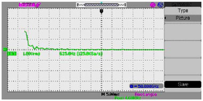
Harmonic spectrum of the five-level inverter output voltage
Harmonic spectrum of the three-level inverter output voltage
Output voltage waveform (five-level inverter)
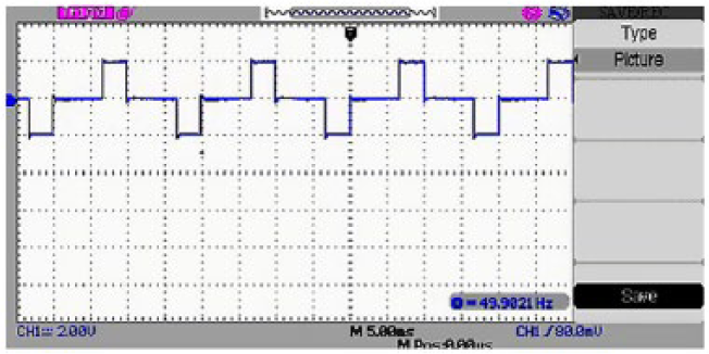
Output voltage waveform (three-level inverter)
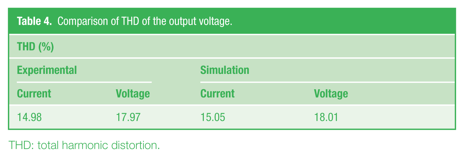
With reference to Table 4 , a comparison of THD of the output voltage has been done. It is evident that the results of simulation are closer to the experimental values.
Comparison of THD of the output voltage.
THD: total harmonic distortion.
VII. Conclusion
A complete simulation and prototype model of a cascaded H-bridge five-level inverter has been proposed in this paper. The prototype model consists of a cascaded H-Bridge five-level inverter power circuit, PIC microcontroller, and PV panel. The cascaded H-bridge five-level inverter with PI controller employing SPWM technique is found to be better when compared with the conventional two-level inverter. The proposed controller adjusts the inverter PF and manipulates the distribution of the reactive power between the cells to maintain the stability of the inverter. The experimental results are presented to confirm the simulation results under PV conditions and proved that with this inverter strategy, harmonics are reduced to a low value. It can be extended further by increasing the number of levels in multilevel inverter so that the THD approaches to small value as expected to achieve better harmonic performance of the inverter.
Footnotes
Funding
This work was supported by the Institution of Engineers (India), Kolkata, who provided financial grant for carrying out the research work in real-time application.