
Abstract
This study involves developing a realistic multi-zone cooling plant model with three independent zones and controlling it via a USB-connected computer. Each cooling zone can have different temperature settings, and all parameters are configured by automation control software which is written in C# language. The cooling system has two cascade connected compressors, three solenoid valves and five fans. All these devices are driven by a specially developed microcontroller-based electronic control card. The developed system enables all control parameters and temperature values to be set and monitored by any Internet-connected remote device using web service technology and a secure token mechanism.
I. Introduction
Cooling and cooling technologies are inevitable in our daily lives and in order to meet industrial needs. While cooling technology is used widely in many fields, it is indispensable for long-term storage of food and medicine in particular.
If we take the case of a supermarket with different storage sections for different products, the cooling system should support different cooling temperatures to preserve goods safely.
Such places generally use independent cooling units, and each unit must have a compressor. In the event of the malfunction of a compressor in the refrigeration unit, depending on the fault elimination time, stored products may become at risk. Therefore, a remote control system is extremely important with regard to informing those in charge in the event of failure. In addition, measurements and operating parameters should be remotely monitored and controlled by professionals.
In the literature, there are many studies of temperature control,1–6 advanced control algorithms,7–12 web service applications13–15 and web-based remote monitoring,16,17 but this work brings together these different and independent topics to solve a real problem.
In the first phase of this study, computer-controlled cooling hardware is designed to control three independent zones with different target temperature values using two compressors and three solenoid valves. In the second stage, a web service and control software have been created to monitor and alter the operating parameters and temperature values of the equipment remotely.
This paper consists of six sections, and the developed cooling system structure is described in the second of these sections. In the third section, a mathematical thermistor model is created to achieve high-precision temperature measurement. Then, detailed information about the microcontroller-based electronic control card is given in the fourth section. The fifth section describes the specially developed desktop automation software, the web service–based control algorithm and the token-based secure authorization mechanism. Finally, the last section offers a conclusion to this study.
II. The Developed Cooling System Architecture
The developed multi-zone cooling system consists of four subsystems in terms of cooling hardware, an electronic control card, control software and a web service. The cooling hardware has three separated cooling zones which have equal volume but different temperature settings. The cooling hardware consists of two compressors, a condenser, an accumulator, two condenser fans, a dryer, an observation glass, three solenoid valves, three capillary tubes and three fans and three evaporator coils inside the cooling zones. The cooling system uses R-134a (CH2FCF3) as a refrigerant. The overall system architecture of the developed cooling control mechanism can be seen in Figure 1 .
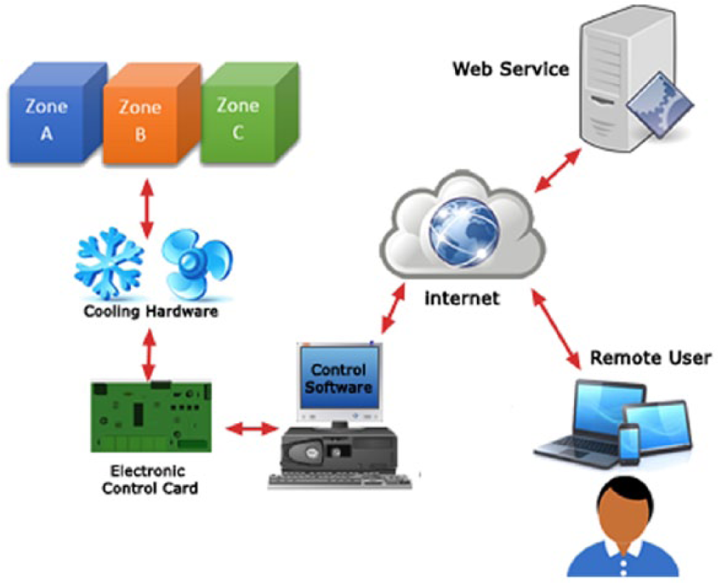
The overall system architecture of the developed cooling control mechanism
The developed cooling hardware is 280 cm wide, 166 cm high and 90 cm deep. The total volume of the cooling zones is 1.88 m 3 . Figure 2 shows the realized multi-zone cooling plant model and the control software working on a computer.
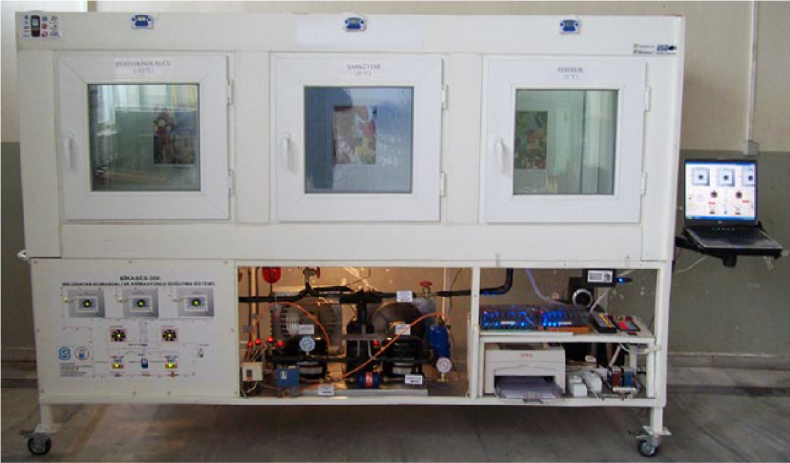
Cooling hardware model connected to a laptop via a USB cable
III. Temperature Measurement and Modeling a Negative Temperature Coefficient Thermistor
Temperature measurement is a common and vital process in control engineering. There are many ways to measure various ranges of temperature. Different types of sensors and temperature measurement methods are used depending on the desired temperature and sensitivity range. For example, a thermal camera can be used when the temperature is high and direct contact is risky. At the same time, PT100 platinum sensors can be used when the endurance limits of the sensor are higher than the measured temperature value because of their linear characteristics. But neither of these is a cheap and feasible solution for refrigerator applications.
The most common temperature-sensing element is a thermal resistor (thermistor). This is a kind of resistor whose electrical resistance is changed according to the environment temperature. It is common and popular because it displays large and linear changes in resistance in proportion to small changes in temperature.
There are two types of thermistor. If the electrical resistance decreases while the temperature increases, it is called a negative temperature coefficient (NTC) thermistor, whereas when the opposite is true, it is called a positive temperature coefficient (PTC) thermistor.
Before using an NTC, its temperature characteristics must be determined. NTC characteristics show differences according to the rate and type of materials used in the production. Therefore, to provide a realistic thermistor model, its resistance is measured at different temperatures in a specified range so that the thermistor coefficients can be determined, as indicated in equation (1)
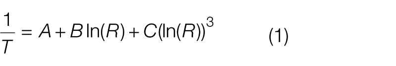
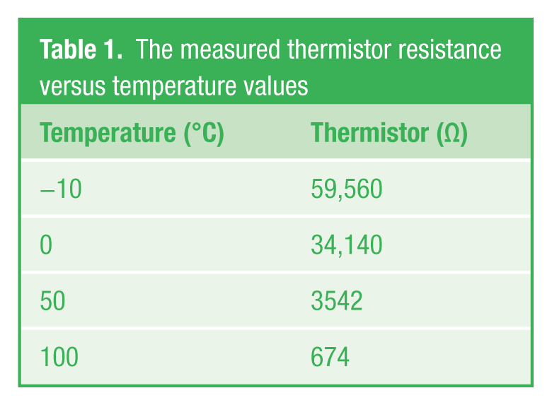
Equation (1) is a simplified version of the Steinhart–Hart equation. 18 T represents the temperature (in Kelvins) and R is the resistance at T (in Ohms). A, B and C are the Steinhart–Hart coefficients. To find these coefficients, at least three operating points should be known. 19 Table 1 gives four operating points for the chosen thermistor.
The measured thermistor resistance versus temperature values
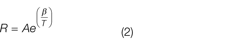
If the material constant of the thermistor (the beta value) is known, thermistor resistance can be calculated using equation (2). In this equation, R is the thermistor resistance at temperature T, A represents the constant of the equation, β is the material constant, and finally T is the thermistor temperature in degree Kelvin
In this study, 10-kΩ NTC has been preferred because it is both common and cheap. The temperature characteristics of the chosen thermistor can be seen in Figure 3 .
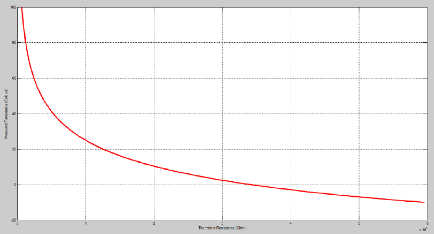
Measured thermistor resistance versus temperature values
In order to measure the NTC resistance, the resistance value should be transformed to a potential difference unit (voltage). For this purpose, a current is passed through the NTC, and the voltage value is measured. The current flowing through the NTC is a waste of power, and this current causes the NTC to heat up. This event causes measurement error, with this phenomenon being referred to as “self-heating.” To prevent such a situation, a high-value resistor is connected in series to the NTC. In the electronic control card that has been produced, the 10-kΩ NTC is used as a temperature sensor, and a 10-kΩ resistor is connected in series as a voltage divider. Figure 4 illustrates the measured voltage drop and the calculated mathematical model values according to the temperature value.
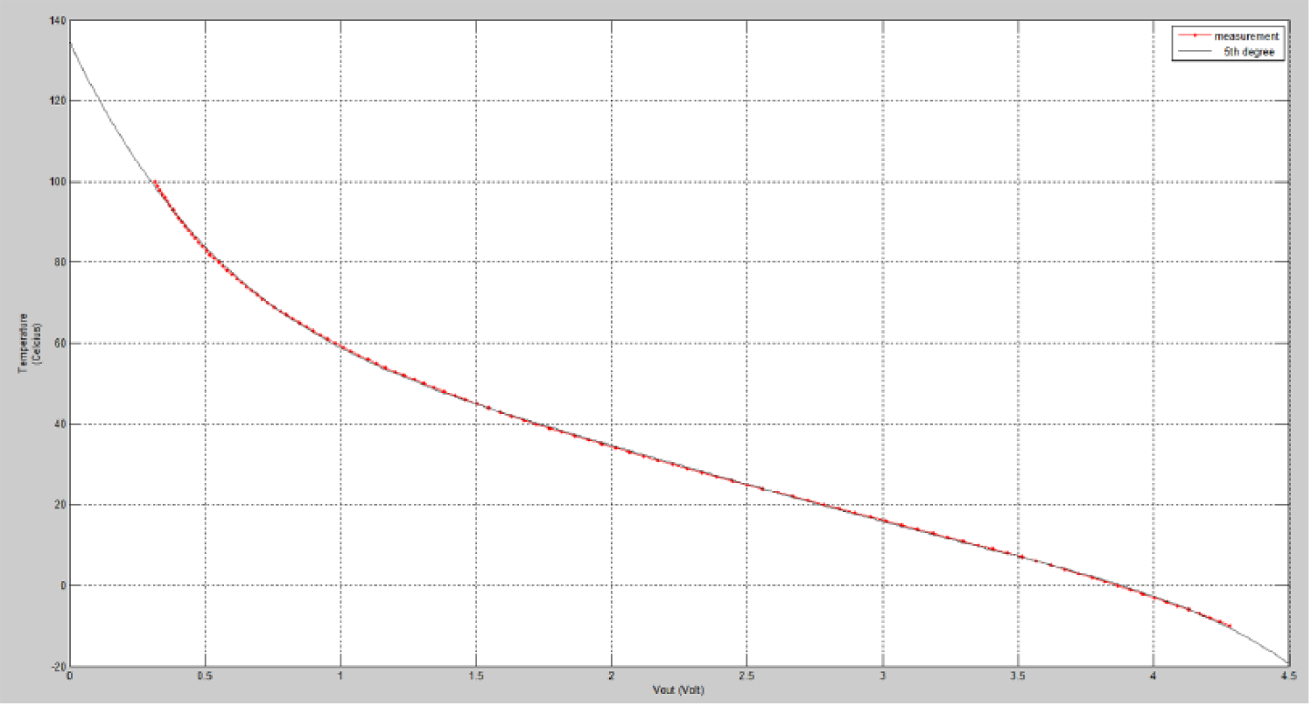
Voltage drop measurement on NTC and fifth degree polynomial function
The mathematical model of the thermistor is obtained using MATLAB software, using a curve fitting technique. The calculated coefficient values and the fifth degree polynomial equation are given in equation (3)
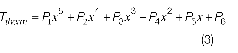
P1 = −0.587, P2 = 7.589, P3 = −38.6, P4 = 97.376, P5 = −141.78, P6 = 134.91.
To get a high-precision temperature measurement, the electronic control card measures the voltage drop on NTC in 10-bit resolution and sends data to the automation software via a USB connection. The desktop software then converts the voltage value to the temperature value in Celsius using equation (3).
To obtain more reliable temperature values, the developed software system uses a low pass filter and utilizes equation (4). The initial value of α is determined as 0.8, and it can be changed according to the measured values
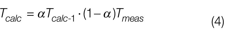
where Tcalc is the calculated temperature value, Tcalc−1 is the previous calculated temperature value and Tmeas is the measured temperature value.
IV. Microcontroller-Based Control Card Architecture
The electronic control card consists of a PIC 18F4550 microcontroller and the input–output units attached to it. It runs at 48 MHz clock speed, and it has an on-chip USB transceiver with an on-chip voltage regulator, 32-kB program memory, 2-kB data memory and 24 I/O pins. A 10 × 10 bit analog-to-digital (A/D) converter is also included.
The input unit has seven NTCs to allow it to take temperature measurements from seven different points. TLP521 series optocoupler integrated circuits (ICs) are used in an optical isolation layer, and a ULN2803 IC and relays are placed in the output layer to drive compressors, solenoid valves, fans and alarm devices. The structure of the microcontroller-based electronic control card is also seen in Figure 5 .
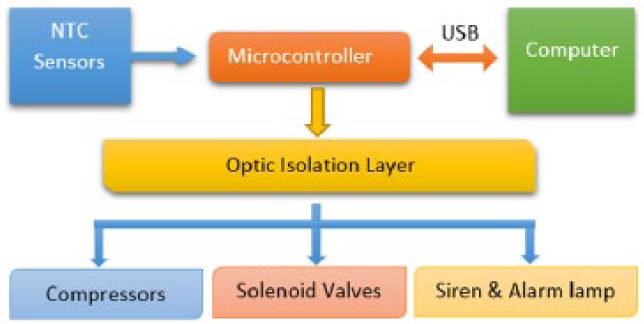
The architecture of the developed microcontroller-based electronic control card
The desktop automation software and the control card communicate using a duplex USB connection. Since the Windows operating system recognizes the electronic control card as a human interface device (HID) device, there is no need to install any driver.
In order to provide electrical isolation and stable operation, an optical isolation layer is located between the microcontroller and the output units. The output unit has relays to manage the compressors, fans and solenoid valves controlling the flow of the refrigerant, a siren and an alarm lamp in case of a problem.
V. Control Software and Web-Based Control Architecture
A. Cooling control software
Control software has been coded in C# programming language using a Visual Studio 2010 integrated development environment. The software has three different usage modes—automatic, manual and the web-control mode. The developed desktop application directly manages 10 digital outputs and 7 analog inputs. NTC thermistors are connected to the analog inputs, and these analog data are converted to a numeric value between 0 and 1023 by the embedded microcontroller program code. The automation control software also converts 10-bit digital values to temperature in Celsius using equation (3). A screenshot of the control software is given in Figure 6 .
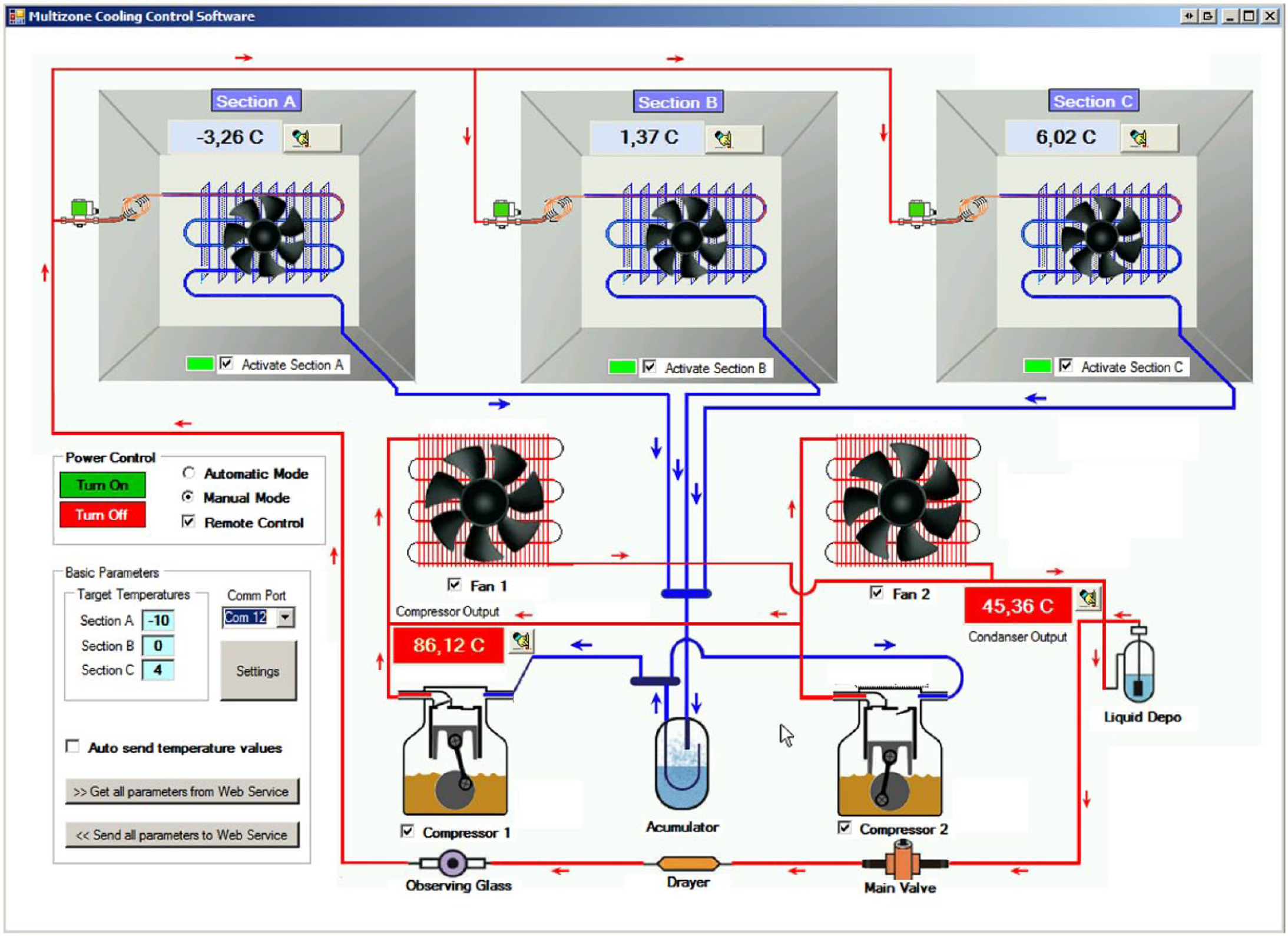
A screenshot of the developed multi-zone cooling control software
The control software interface shows all the components contained in the cooling equipment. The current operating status of the components and the measured temperature values are displayed in real time. The control software communicates continuously with the electronic control card via the USB port and sequentially reads the NTC values. It uses a specific command structure to send and receive data. For example, the computer software sends a “<A3###>” command to get temperature information of the third NTC, and then, the electronic control card measures that analog input and may respond with a string “<A32A8>” to transmit the analog value of the third NTC. The returned value (2A8h in this example) is always in hexadecimal format. In manual mode, the user can disable or activate fans, solenoid valves and compressors one by one and perform temperature measurements.
In automatic mode, both compressors and fans are turned on until the measured temperature values reach the previously set temperature values. When one of the zones reaches the target temperature, the solenoid valve at the entrance to the respective zone is closed to stop a refrigerant flow. Both compressors are stopped when the target temperature is achieved in all zones. The compressors’ working times are calculated to determine which compressor will be the main compressor. The compressor that has worked less is chosen as the main compressor, and the other one is the auxiliary one for the next run. This approach provides a balanced aging with regard to both compressors.
m1, m2, m3 and M values are calculated according to equations (5), (6), (7) and (8), respectively. These values are used to determine which compressor or solenoid valve will be turned on
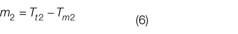
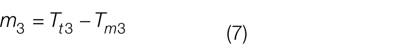
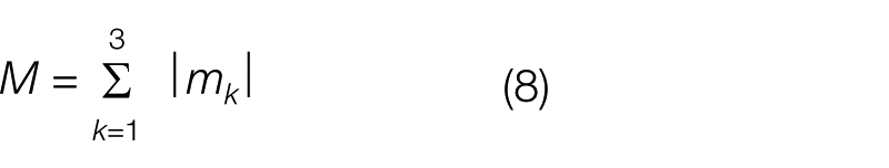
where Tt1 is the target temperature value in Celsius for Zone A, Tm1 is the measured temperature value in Celsius for Zone A, Tt2 is the target temperature value in Celsius for Zone B, Tm2 is the measured temperature value in Celsius for Zone B, Tt3 is the target temperature value in Celsius for Zone C, and Tm3 is the measured temperature value in Celsius for Zone C.
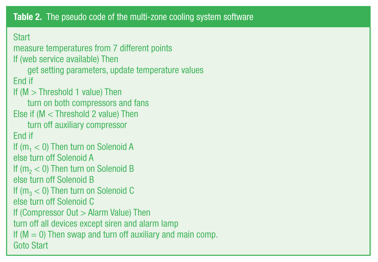
The working algorithm for the multi-zone cooling system is given in Table 2 .
The pseudo code of the multi-zone cooling system software
B. XML-RPC-based web service software
A web service is a method of performing remote method calls over HTTP protocol using eXtensible Markup Language (XML) formatted messages. It is a modular program aimed to support practical machine-to-machine communication over a network. A request from the client side calls up a certain method on the web server. After the execution of the server side method, a return value is sent back to the client. An XML-Remote Procedure Call (XML-RPC) message is actually an HTTP-POST request. Both request and response messages are XML formatted and readable by human and machine.20,21
The web service software is not tied to a particular platform and is accessible from anywhere if the client application has an HTTP access to the server. Therefore, the applications created in different platforms using different programming languages can also use a web service without any limitations.
In this study, the web service software has been developed using the C# language and the ASP.NET platform. The service software uses the XML-RPC protocol. The developed control software and remote users can connect to the web service software using “getTemperature” and “setParameter” methods to monitor measured temperature values or change the operating parameters of the cooling system remotely.
A typical XML-RPC request code to obtain the current temperature value of Zone A is given in Table 3 , and the corresponding XML-RPC response is shown in Table 4 .
An example XML-RPC request to obtain the current temperature value in Zone A
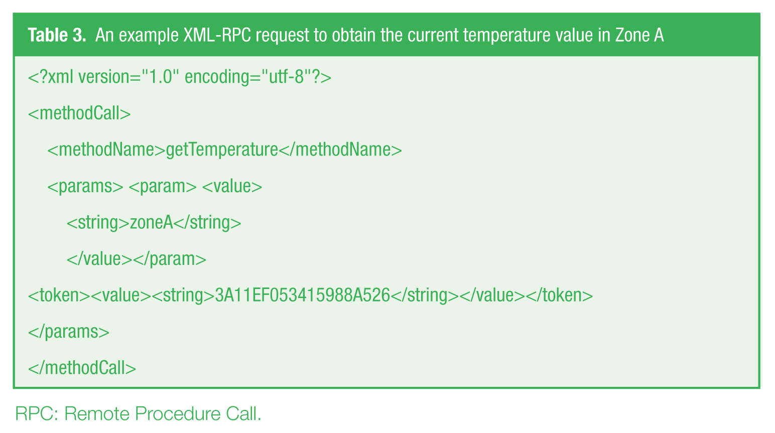
RPC: Remote Procedure Call.
An example of an XML-RPC response packet, including current temperature value in Zone A
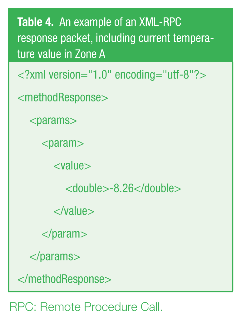
RPC: Remote Procedure Call.
C. Token-based secure authorization control system
A token-based secure authorization control mechanism has been developed to protect the cooling plant against unauthorized remote communication attempts.
This mechanism consists of three components: user, authorization service and remote cooling plant. First, the user has to take a valid token from the authorization web service to obtain actual temperature values or to change operation parameters.
As can be seen in Figure 7 , the user sends a token request to the authorization web service by logging in. The authorization service generates a token and then sends this back to the user. The user then sends a command to the remote cooling plant with a valid token. The remote cooling plant sends the token and user information to the authorization service to identify whether or not the token is valid. If the token is valid, the cooling plant operates the command, otherwise the command is ignored.
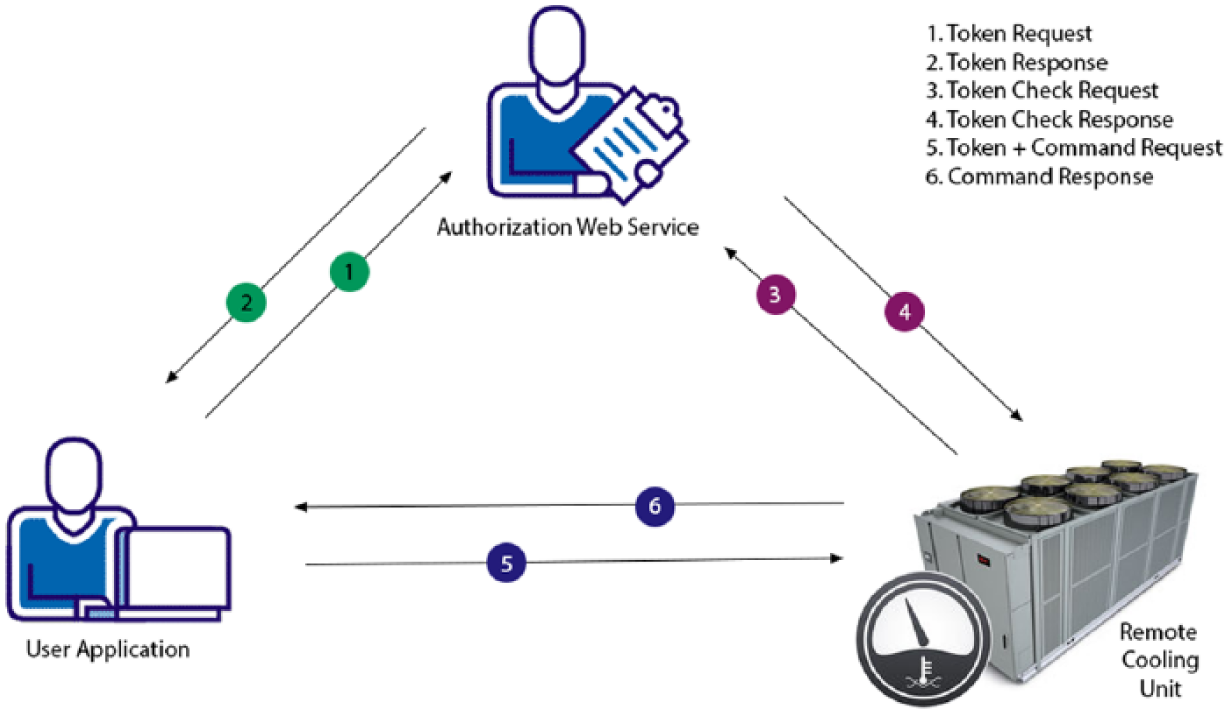
The general scheme of the token-based secure authorization mechanism
The authorization web service hosts a token generator and token validator services. The token generator can produce three different types of token. The first type is a single use token and it can be used only once. It needs to be regenerated after each command request. The second type of token has a counter value, and this value decreases after each command request. When the counter value reaches zero, the token expires. The third type of token is time limited, and the life time is determined by the authorization service. It can be used without any restrictions except in terms of the expiration date.
Token information is 15 bytes long and consists of six fundamental parts as can be seen in Figure 8 .

The essential parts of a token
Three types of token provide different users with various authorization levels and limited connection time. In order to increase security levels, the Internet protocol (IP) restriction method and the Secure Socket Layer communication protocol can also be used.
VI. Conclusion
In this paper, first, multi-zone cooling hardware is designed to allow a computer to control three different zones. For this reason, a microcontroller-based electronic control card has been developed to communicate and control the cooling system via desktop software. Second, the control software is coded in C# language to become an interface between users and web services. In addition, web service software has been created to enable different mobile and desktop users using various platforms to monitor and control different remote systems via Internet connection. In this fashion, the measurements and working parameters of the various physical systems can be recorded in a web server to evaluate and analyze the collected data later on. To improve connection security, a token-based authorization web service has been implemented.
The developed hardware and control software can also be used as a realistic testbed to test and compare the different control algorithms widely used in cooling technology.
Footnotes
Funding
The author(s) received no financial support for the research, authorship and/or publication of this article.