
Abstract
This paper addresses in a simplified manner the basics of pH measurement and control.
I. Introduction
Tech Talk is a series of papers designed as a ‘pull out’ reference library. The aim is to disseminate knowledge of both the fundamentals of measurement and control and their practical application. This paper addresses in a simplified manner the basics of pH measurement and control.
pH, an abbreviation of the Latin term ‘pondus hydrogenii’, is a measure of the hydrogen ion concentration in a water-based solution and represents the degree of that solution’s acidity or alkalinity.
pH measurement and control is widely applied throughout industry and elsewhere. It is extensively used to monitor and control potable water treatment and the neutralisation of domestic and industrial effluent streams. Other uses can be found in food and pharmaceuticals’ production, swimming pool water quality control, boiler feed water monitoring, soil acidity monitoring and many more. A more comprehensive treatment of potential applications can be found in the bibliography listed at the end of this paper.
II. Chemistry
Acids react with water forming ‘acidic’ solutions which have a relatively high concentration of hydrogen ions. In contrast, alkalis react with water forming ‘base’ solutions, which have a relatively high concentration of hydroxyl ions. The pH of a solution is defined by the Sorenson equation as the negative logarithm of the concentration of hydrogen ions (H+)
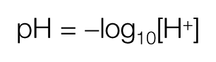
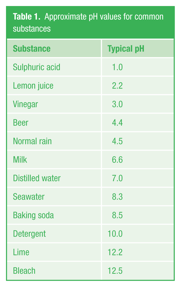
This definition results in pH being represented (at a reference temperature of 25 °C) by a scale of 1–14. This is known as a thermodynamic pH scale. Acidic solutions have a pH < 7, alkaline solutions have a pH > 7 and neutral solutions have pH = 7. Typical pH values for common substances are shown in Table 1 .
Approximate pH values for common substances
The temperature of a solution can have an effect on the dissociation of hydrogen and hydroxyl ions. If not taken into account, this can lead to a discrepancy between a pH reading taken under laboratory conditions and one taken at a process site. The magnitude of a potential error is dependent on the temperature deviation from the 25 °C reference and the temperature coefficient of the solution (pH change per °C).
III. pH Measuring Electrodes
pH is determined using two electrodes which are often combined in a single insertion probe. A pH measuring electrode is typically made using a glass or plastic tube containing a constant pH solution (buffer) and a conductor, plus a reference electrode containing a reference electrolyte and a conductor to complete the circuit. With a combination electrode, the pH and reference electrodes are located within one probe assembly. Temperature compensation is usually facilitated using a thermistor incorporated in the combination probe assembly.
When immersed in a solution, the electrical potential generated is a measure of the solution’s pH and is connected to a receiving instrument for temperature correction and amplification.
Typical probe assemblies are shown in Figures 1 – 3 .
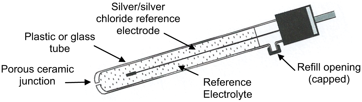
Reference electrode
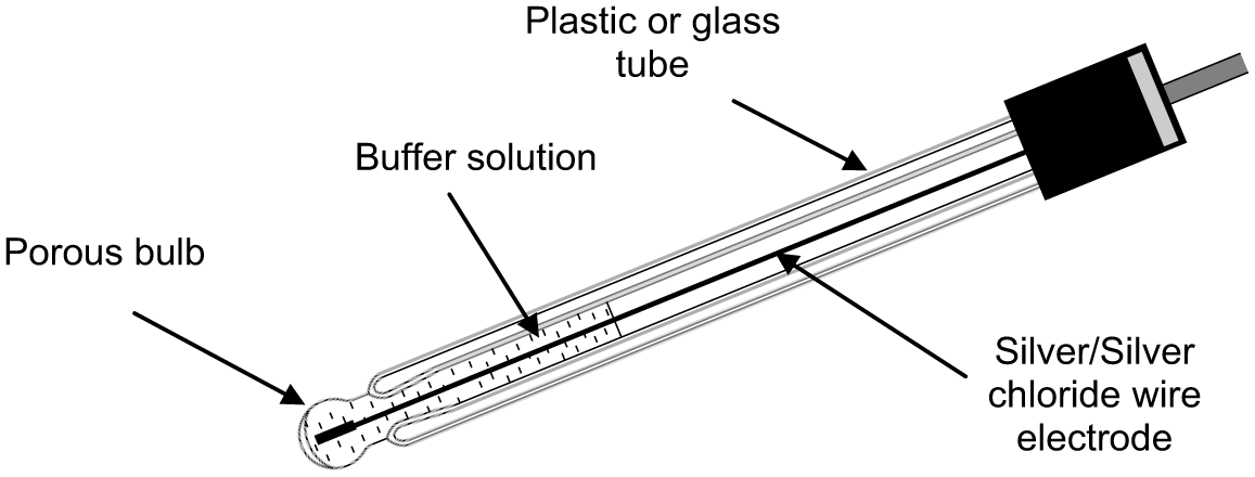
pH electrode
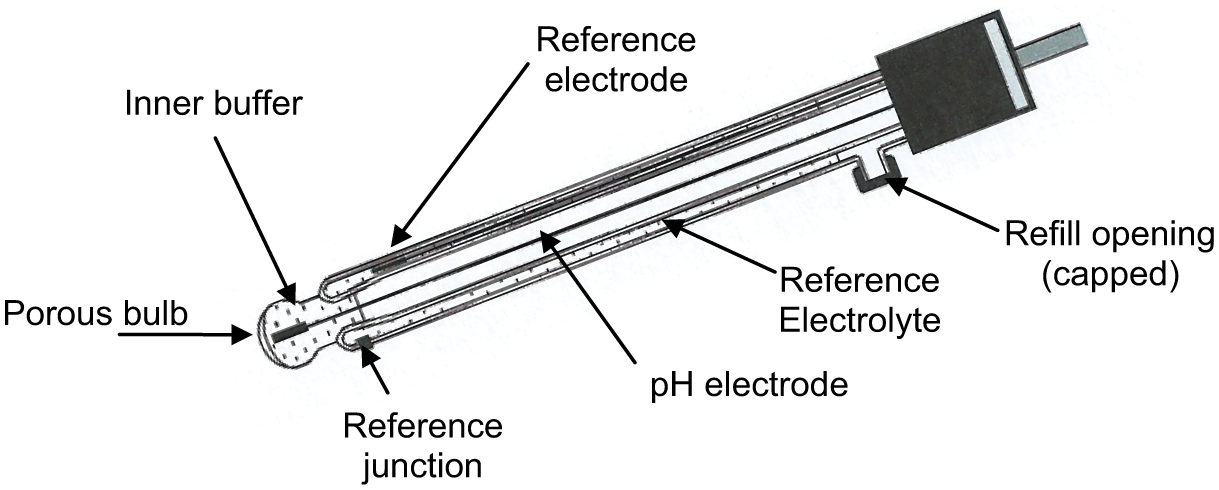
Combination pH and reference electrode
IV. pH Electrode Mounting
Laboratory test kits may incorporate separate or combination probes, whereas the combination probe is particularly suited for use in a permanent installation. The use of a combination probe has an added advantage in that the reference and pH probes will always be at the same temperature. The probe assembly can be installed as a tank immersion unit, direct into a process pipe or in a bypass sample loop flow-through arrangement. On-line measurement requires frequent sample checking and calibration, as the probes can become quickly fouled and sluggish. Ease of access for system calibration under clean/sheltered conditions is essential.
V. Instrument Measuring Loop Scaling
It is worth remembering that the pH scale is logarithmic. A one-unit pH change means ten-fold change (one order of magnitude) in the H+ ion concentration. All solutions with pH in the range 4–10 have concentration of H+ and a hydroxyl ion concentration (OH−) lower than 10−4 mol, which can be altered with small additions of acid or base.
The logarithmic pH scale potentially makes automatic control of pH problematic as regards controller tuning. For this reason, it is necessary to understand the pH limits of the solution both before and after the specified addition of acid or base chemicals and thus to keep the loop scaling as narrow as practical, for example, 6–8 pH.
VI. Titration
Titration is normally the province of the Chemical Engineer. This brief explanation is included to help explain how the reagent dosing range for pH control systems is determined.
Titration is required in order to determine the volume ratio of a chemical (reagent) to be dosed into a solution in order to bring about a required pH endpoint. Titration is usually carried out under laboratory conditions and is the gradual addition of one solution of a known (standard) concentration – the titrant, to a known volume of another solution of unknown concentration – the analyte, until the chemical reaction reaches neutralisation and stops (the endpoint or equivalence point). This can be observed using a calibrated pH meter or by colour change (litmus) papers. The measurement of the dispensed titrant volume then allows the calculation of the analyte content based on the stoichiometry of the chemical reaction. The data thus obtained can then be used to produce a ‘titration curve’ ( Figures 4 and 5 ).

Adding acid into an alkali solution
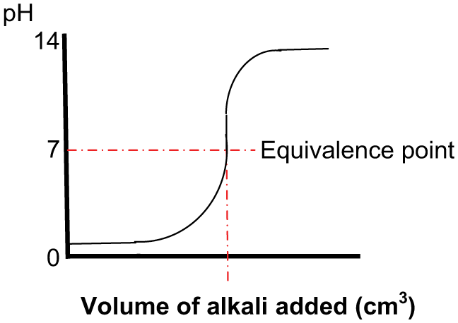
Adding alkali into an acid solution
This knowledge allows the determination of the chosen reagent volume flow rate with respect to the analyte flow rate and correct sizing of reagent metering pumps or control valves.
The above curves are typical and will vary depending on the pH of the acid or base solution – the analyte being titrated and the relative pH of the titrant.
VII. Calibration and Maintenance
For process critical applications, it is often worth considering that an off-line fully calibrated back-up system be kept available, as calibration with buffer solutions is time consuming.
On-line pH measurement trends will, in most cases, show scattered measured values, even when the process media are stable. Scattered measured values alone are not always an indication of a fault. It can be caused by normal variations in the measured media. However, the scattering of the measured values may increase with the age of the pH electrode.
Sensor performance can be determined by measuring an appropriate pH buffer. If the measured value is within the required specification, recalibration of the sensor/amplifier is unnecessary. Recalibration frequency can usually be determined after a series of regular calibration checks. Dirty or aggressive fluids can in certain cases mean that very short recalibration intervals are needed.
VIII. Buffer Solutions
pH measuring systems are calibrated using buffer solutions with a known pH value that provide a number of calibration points on that part of the titration curve representing the span of the measurement and indication equipment.
Prior to system calibration, adequate warm-up time for the analyser should be allowed and the probe and buffer solutions should be at the same (room) temperature. As the buffer solution will absorb CO2 from the atmosphere over time, resulting in increased measurement uncertainty, the fluid should not be stored for more than a few days once the container has been opened for use.
When purchasing buffer solutions, the quoted ‘Uncertainty’ should be checked against the Standard required for the application and a Certificate of Calibration obtained.
IX. pH Control
Having obtained a titration curve for the ‘process’, the control system designer can note how the pH changes per unit of reagent addition (dosing) and observe the limits for reagent volume flow. The equivalence point (the point of greatest change) is also apparent. For this reason, attempting to control pH near to the equivalence point will often prove problematic. To avoid this situation, neutralisation of a strong acid with a weak base, or a strong base with a weak acid, will result in better control than strong-acid, strong-base neutralisation. Adequate mixing of the analyte and reagent, plus sufficient (but not excessive) dwell time to allow the reaction to complete, is essential for stable control.
The control system to be employed depends on a number of factors which include the flow rate and pH variations of the process stream to be treated, the strength of the reagent to be dosed, the accuracy of control required (including excursion limits) and the method of dosing the reagent/s. The systems described below comprise a basic treatment of the subject.
A. Continuous neutralisation control
Figure 6 shows a typical neutralisation pH control scheme. The reagent control valve or metering pump is sized to dose reagent by per unit volume over that part of the titration curve of interest. Primary control is exercised by metering the process stream flow and controlling the dosing reagent flow rate in direct proportion via a flow ratio controller. The resulting pH is measured as close as practical after the mixing point and dwell tank. The pH transmitter signal, which should be scaled as narrow as practical over the control range of interest, is connected to a pH controller. The controller output signal from this controller is used to fine trim the amount of reagent dosed by adjusting the ratio set point of the flow controller.
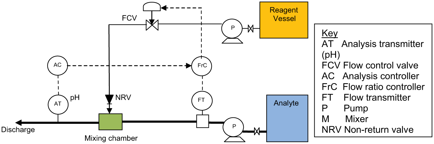
Continuous neutralisation control
Where the titration curve indicates a requirement for relatively high reagent addition approaching the equivalence point, stable control may prove troublesome due to the turndown ratio limitation of the dosing control valve or metering pump. Other issues are as follows:
The rate of flow range of the process stream;
The speed of response of the reagent controlling device;
The residence or dwell time of the mixing plant arrangement;
The measuring instrument speed of response;
The amount of overshoot or undershoot arising from the control system as a whole.
Control valve Rangeability (R) is the ratio of maximum controllable flow to minimum controllable flow, whereas Turndown (T) is the ratio of the normal maximum flow to minimum controllable flow. Turndown differs depending on the type and flow characteristic of the valve selected, but in general, T = 0.7 × R, where R is between 20 and 50. To overcome the turndown problem where a larger ratio is indicated, it is possible to install two control valves in parallel, a large one and a small one, with actuators responding to a controller split range output signal. At high flow rates, the small valve is full open and the large valve is modulating. At low flow rates, the large valve is closed and the small valve is modulating.
On processes where the volume of titrant to be added exceeds the rangeability of a dosing control valve design, then recourse may be made to the use of two metering pumps (one large and one small with variable speed or stroke) operating in parallel, the smaller pump being employed for fine control approaching the pH set point.
Experience suggests that Proportional + Integral controller action is likely to be the most successful. Derivative control action is rarely used.
B. On–off neutralisation control
Figure 7 depicts a basic set up for reagent addition where there is some latitude (control offset) in the final pH value achieved for the discharged fluid. This is typical for domestic and small-scale industrial effluent discharges. With this form of control, a long residence time and adequate mixing to ensure that the reaction is complete are essential design considerations. The flow rate of the reagent is manually set on a regulating valve, and the pH controller simply opens and closes the control valve (or starts and stops a metering pump) when the measured pH value crosses the controller set point.
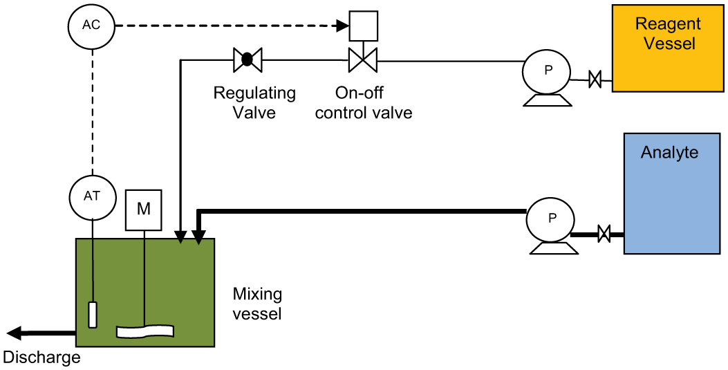
On–off neutralisation control
For installations requiring the addition of either acid or base reagents depending on a varying analyte pH, parallel acid and base reagent dosing systems can be installed and the on–off controller designed to operate the required control valve or metering pump depending on excursions above or below the control set point.
Footnotes
Funding
The author(s) received no financial support for the research, authorship, and/or publication of this article.