
Abstract
In this paper, an experimental set-up for the measurement of actuation properties of shape memory alloy wire actuators is presented. A test rig is designed and developed to characterise shape memory alloy wire actuators. The test rig is equipped with force, displacement and temperature sensors. The test rig is validated by measuring the strain of bi-atomic nickel–titanium shape memory alloy actuators by supplying various actuation currents. At 420 mA, the 0.15-mm-diameter nickel–titanium actuators underwent 3.25% strain which lies within the guideline range (3%-4%) reported by the manufacturer of the actuators.
I. Introduction
Shape memory alloys (SMAs) ‘remember’ their shape. 1 This is due to a property known as shape memory effect (SME). These alloys are usually equi-atomic type (50% nickel and 50% titanium), but other elements can readily be added to alter the properties. They have found extensive use in many engineering and medical applications. 2 Those applications range from structures to actuators for microgrippers. SMA actuators possess certain advantages over conventional actuators. They possess high strength-to-weight ratios. They can be used as an actuator and a sensor simultaneously. This can result in the eliminations of the position feedback sensors. 3
SMAs possess very high actuation energy density (energy produced per kilogram of mass); however, they have low actuation frequency (actuation stroke is of shorter duration than the relaxation stroke) because of the long cooling times. The cooling time depends on many factors: the type of material, diameter, the ambient temperature and the type of conduction and convection. Hence, they are particularly useful in applications that do not require fast operations.
SMA actuators possess two phases as shown in Figure 1 . They are martensite (low-temperature phase) and austenite (high-temperature phase). Young’s modulus for martensite is 28 GPa and that for austenite is 75 GPa. 4 Hence, SMA in martensite phase can easily be deformed. When SMA is heated to transformation temperature, it transforms back to austenite. This transformation results in a contraction of up to 8% of length and stress of 600 MPa.
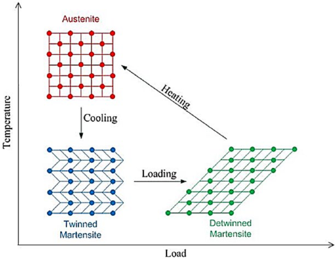
Phase transformation in shape memory alloys
SMAs possess a highly nonlinear and hysteretic behaviour. The behaviour of the actuators depends on the bias force, heating (actuation) time, cooling (relaxation) time and ambient temperature. Hence, the characterisation of SMA actuators plays a very important role in the development of SMA actuated systems. 5
The knowledge of actuation characteristics of an actuator is of fundamental importance as this helps to develop a better system. The strain and force characteristics of SMA actuators are highly dependent on actuation current and bias force; hence, these characteristics must be carefully determined for developing an application that works as stipulated. Some experimental set-ups to characterise SMA wire actuators have been reported in the literature.6–8 However, the measurement of displacement in those systems is carried out using Hall Effect position sensor or linear potentiometers which affect the measurement. The test rig reported here uses laser displacement sensor to accurately measure the displacement.
II. Experimental Set-up
The photograph of the test rig is shown in Figure 2 . The block diagram of the test rig is shown in Figure 3 . Various components of the test rig are described in the following subsections.
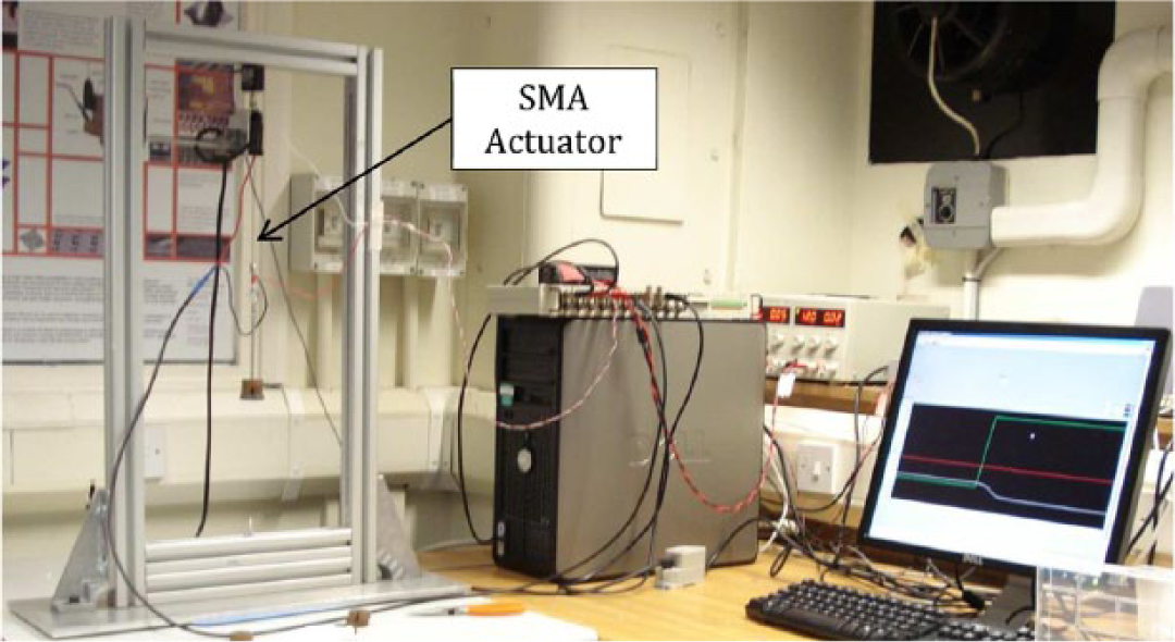
Experimental test rig
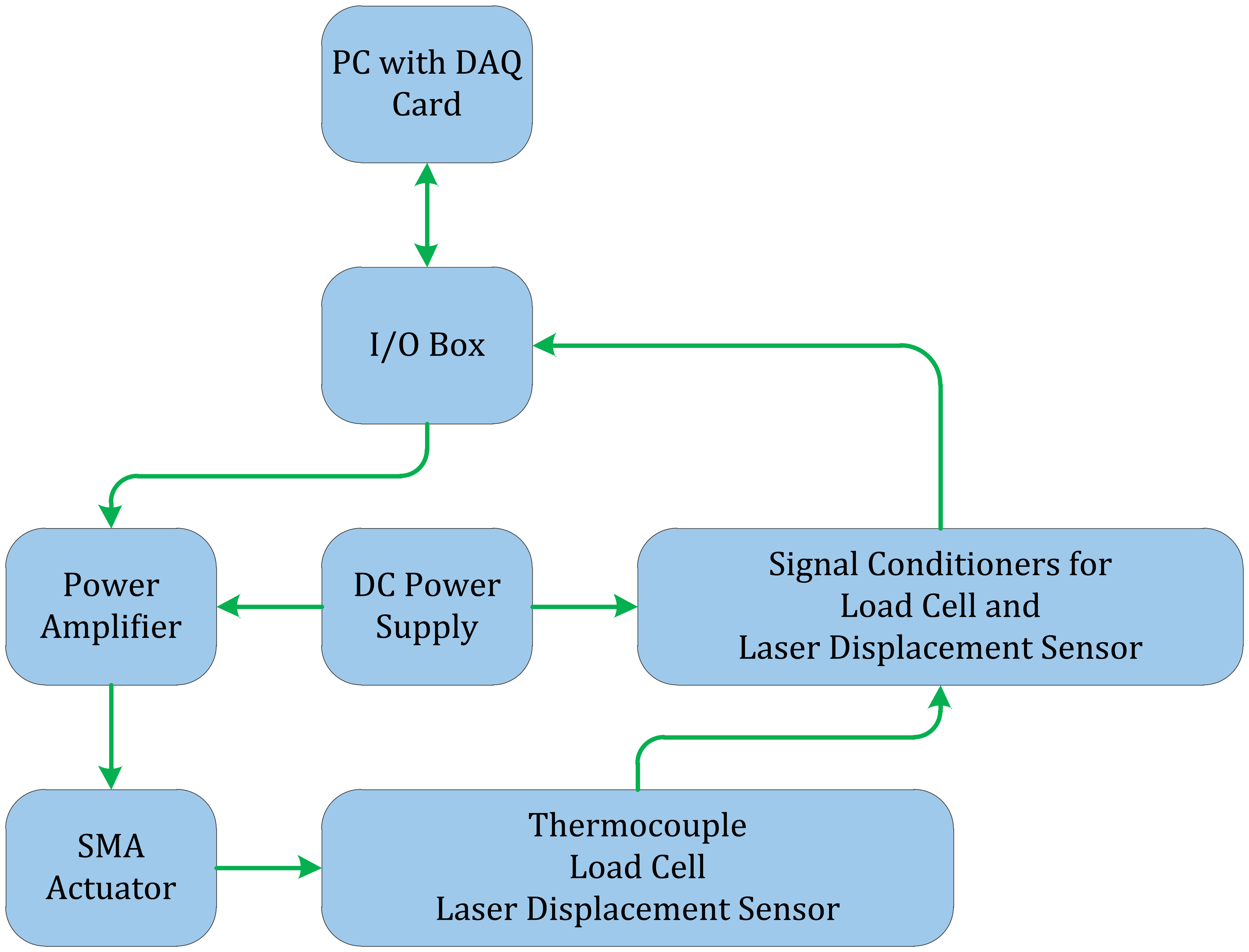
Block diagram of test rig
The 750-mm-high structure was built on the solid aluminium base measuring 200 mm wide, 600 mm long and 10 mm thick. The columns were secured to base using brackets. The test rig was equipped with the following sensors to take measurements during the conduct of tests on single wire and bundled actuators.
Laser displacement sensor: To measure the length of stroke (strain) of the actuators;
Load cell: To set the bias force in the actuator for both dead weight and spring biased testing;
K-type thermocouple: To monitor temperature of the actuators.
The test rig may be used for both dead weight and extension spring bias conditions. To isolate the test rig from air currents, an enclosure made of Perspex® sheet was also made.
To accurately capture the strain behaviour of the actuator, a laser displacement sensor was used. The sensor had a measurement range from 80 to 180 mm, beam spot of 0.7 mm × 1.4 mm and a resolution of 100 µm.
The load cell was used to set the bias force of the actuator. The load cell used in this work was the Transducer Techniques MDB 2.5. The top side of the load cell was secured to the test rig, and the bottom side was attached to the bias load. Signal conditioner was obtained from the same manufacturer.
Measurement of temperature of SMA wires can be made using thermocouple. Measurement using thermocouples are to be made very carefully as slippage (due to actuation) of the thermocouple and heat loss to the thermocouple affect the accurate measurement. Since SMA wire actuators may be very thin (about 0.15 mm or even smaller diameter), fine gauge thermocouples having diameter of 0.025 mm were tried first for better attachment to the actuator. However, these thin thermocouples proved too weak to properly attach to the actuator and to the data acquisition (DAQ) connector block. It was then decided to use K-type thermocouples having a diameter of 0.125 mm. The response time of this thermocouple was 1 s. The special heat-resistant tape was used to attach fine gauge thermocouple bare wires to actuator.
A DC power supply was used to supply power to the amplifier and signal conditioners of the load cell and displacement sensor. In this research, the SMA actuator was powered by the program developed in LabVIEW® graphical programming environment. The LabVIEW program was used to generate an output signal through a DAQ card. Since the maximum current that can be drawn from that DAQ card was only a few milliamperes, a power amplifier was used to supply large current to the system.
NI-PCI-MIO-16-E4 was used for DAQ. The card has 16 single-ended and 8 digital input channels, a sampling rate of 500 kS/s, 12-bit resolution, voltage range of −10 to 10 V, 2 analogue output channels and an update rate of 1 MS/s.
III. Test Procedure
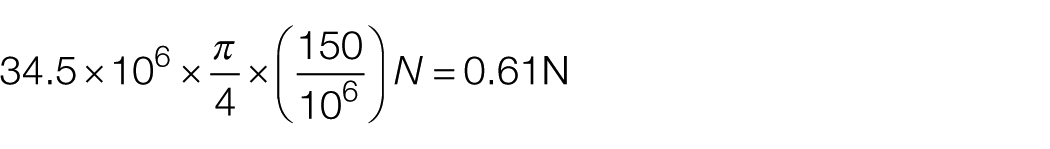
The SMA actuators obtained from Dynalloy® Inc. were used to validate the test rig. The diameter of the nickel–titanium SMA actuator was 0.15 mm. The transformation temperature of those actuators reported by the manufacturer was 90 °C. The manufacturer of the actuators recommends a bias stress equal to 34.5 MPa. 9 The bias force for 0.15-mm-diameter actuators is, therefore, calculated as follows
The following procedure was followed to measure strain characters of SMA actuators:
The wire actuator was cut to a length of 90 mm using a pair of pliers suitable to cut high-speed steels. The gauge length, crimp terminal.
Ferrules were used inside the crimp terminals so as to ensure strong grip to avoid any slippage of the actuator during testing.
Actuator was crimped on both sides using crimp tool.
Crimped actuator was mounted on the test rig.
The extension spring was attached at the lower end of the actuator to provide the bias force.
Thermocouple was attached to the actuator to monitor temperature. The special heat-resistant tape was used to secure the thermocouple to the actuator to avoid any slip of the thermocouple when actuator contracts and extends.
Initial tension was set to 0.61 N by reading signal from load cell. This was done by manually adjusting the position of the bias spring.
A LabVIEW program was used to generate a step input. Each actuator was cycled 100 times. Each cycle consisted of powering for 5 s followed by cooling for 10 s to completely bring the temperature of the actuator to room temperature. The final strain was then measured at the end of 100th cycle.
Tests were carried out by supplying set current to the actuator. This was done using Maxon Motors servo amplifier as a current regulator.
IV. Results and Conclusion
The flow of current across actuator resulted in the heating of the actuator due to its resistance. This heating caused a contraction of the actuator due to transformation from martensite to austenite. The displacement of the laser target attached to the lower end of the actuator was equal to the length of stroke for that particular cycle.
The results of tests on the actuators are presented in Figure 4 . The horizontal axis represents the time (in seconds) for which the actuation current was supplied. The left side of the vertical axis indicates the length of stroke. Since actuator underwent contraction, the length of stroke is reported as negative. The right side of the vertical axis shows the percentage strain. The percentage strain was found by dividing that length of stroke with the gauge length of actuator (80 mm) and then multiplying the result with 100 as mentioned in following equation

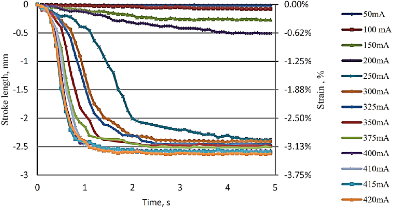
Actuation behaviour of 0.15-mm-diameter actuators
The actuation currents of 200 mA and below did not produce any appreciable strains. For instance, the maximum strain was limited to 0.62% for the actuation current of 200 mA. The reason for very low strains for this band (50–200 mA) of actuation currents is incomplete transformation from the martensite to austenite phase. That is, not all of the martensite was transformed to austenite. The actuation currents of 250 mA and above resulted in the larger phase transformation. As it can be seen in Figure 4 , the higher currents produced larger strains because more martensite was transformed into austenite. As Figure 4 shows, at 420 mA the actuator undergoes a maximum strain (3.25%) in the first second. For the rest of the actuation time, the strain rate is nearly zero. This shows that all of the transformation completed in 1 s. The results compare well with the guideline values reported by the manufacturer. 9 It is provided by the manufacturer that actuators undergo 3%-4% of strain under the spring bias. The 3.25% strain obtained in this work was within this range.
For cyclic applications, the SMA actuator must undergo cooling before it is subjected to heating for actuation. To find out the time for cooling, the actuator was subjected to heating current of 420 mA and was subsequently cooled to ambient temperature under natural convection (without any forced cooling). Figure 5 depicts the heating and cooling patterns for the actuator when subjected to actuation current of 420 mA.
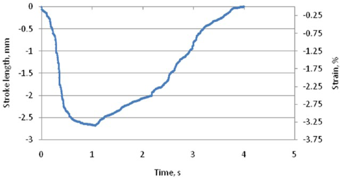
Heating and cooling patterns of the actuator
Figure 5 shows that both heating and cooling phases of actuator are nonlinear. The 1 s of heating at 420 mA caused the actuator to contract 3.25% of length. It took about 3 s to cool the actuator back to its initial unstrained state. Hence, each cycle of operation took 4 s (1 s for heating and 3 s for cooling). For many applications, this long cycle time is a drawback. Hence, external cooling by way of a fan may be considered. However, for applications requiring slow operations, SMA actuators may be considered as a good choice.
V. Further Work
In this work, a test rig to characterise SMA actuators is reported. Following future work is suggested for larger stroke length and faster cyclic speed of SMA actuators:
As the maximum strain found is only about 3.25%, the higher stroke lengths require longer actuators, which may not be practicable with single strand of actuators. Hence, it is suggested to develop a bundled actuator with multiple loops to increase the length of actuator.
The cycle time for the actuator is high (4 s). This long time is not suitable for fast applications. Hence, it is suggested to cool the actuator using some external sources. The suggested methods are grease in tube around the actuator, a small fan or semiconductor cooling devices.
Footnotes
Funding
The author(s) received no financial support for the research, authorship and/or publication of this article.