



Abstract
I. Introduction
Tech Talk: (6) Flow Measurement Basics (Part 1) covered the nature and dynamics of fluid flow with respect to metering considerations. Part 2 looks at some of the commonly used methods of flow metering other than differential pressure methods.
II. Positive Displacement Flow Meter
The positive displacement (PD) flow meter, one of the earliest flow meters, works on the principle of a fixed volume of fluid, gas or liquid, causing a known mechanical displacement in order to mechanically move a counter (totaliser) and/or generate a calibrated pulse output. Various mechanical configurations are available as shown in Figure 1 . PD flow meters are very accurate and have a high turndown ratio which, depending on the application, can be as high as 80:1. They can be used on viscous liquid applications and, in general, require no straight runs of pipe for fluid flow stream conditioning, although relatively high pressure drop with certain configurations can be a concern. PD flow meters are widely used in custody transfer of oils and liquid fluids, particularly motor vehicle fuels, and are used on domestic natural gas and water metering.

Examples of positive displacement flow meters
Fluid viscosity affects the pressure drop, and the presence of solids or entrained air can cause the meter to seize, resulting in mechanical damage. Although some PD meters can tolerate a small amount of entrained solids in the fluid, in dirty fluid applications the use of an upstream particle filter is recommended. If pressure and temperature compensation is applied in gas metering applications, the mass flow rate can be accurately determined.
PD meters providing a rate of flow generate a pulse train with the rate being proportional to the volume flow. An electronic means of integrating the pulses is required in order to totalise the metered volume. The various types of meters available are discussed below.
A. Oval gear flow meters
Rotating oval gears mounted inside a cylinder admit a fixed volume of fluid through the meter for each revolution. As the fluid flows through the cylinder, the pressure of the fluid causes the rotors to rotate at a speed related to the rate of flow.
B. Helical gear flow meters
Rotors in these flow meters are in the form of a helix. As the fluid flows through the meter, it enters the compartments in the rotors, causing the rotors to rotate. The flow rate is derived from the speed of rotation.
C. Reciprocating piston/oscillating piston
Each piston is mechanically or magnetically operated to fill a cylinder with the fluid and then discharge the fluid. Each stroke represents a fixed measurement of the fluid.
D. Nutating disc
The nutating disc flow meter has a round disc mounted on a spindle in a cylindrical chamber. The disc is ‘wobbled’ about an axis by the fluid flow, and each rotation represents an amount of fluid transferred. By tracking the rotation of the spindle, the flow meter determines the number of times the chamber traps and empties fluid and thus determines the flow rate.
E. Rotary vane
A rotating impeller, containing two or more vanes, divides the spaces between the vanes into discrete volumes, and each rotation (or vane passing) is counted.
F. Diaphragm
Fluid is drawn into the inlet side of an oscillating diaphragm and then discharged to the outlet. The diaphragm oscillations are counted in order to totalise the volume flow. This configuration, in double diaphragm form, is frequently used in pumping fluids.
III. Turbine Flow Meters
The axial turbine flow meter consists of a rotor which is driven at a rate proportional to the fluid velocity, to generate a calibrated pulse; Figure 2 shows the in-line form. Flow meters are available that can be inserted into a pipeline via a flanged or screwed ‘T’ connection. Turbine meters generate a pulse train, the pulse rate being proportional to the volume flow. An electronic means of integrating the pulses is required in order to totalise the metered volume.
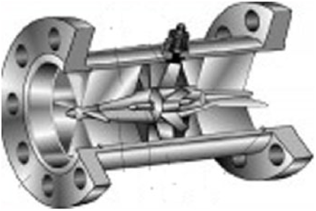
In-line turbine flow meter
An accuracy of ±0.5% of reading over a 15:1 turndown is achievable for kinematic fluid viscosities in the range of 1 × 10⁻⁶ to 2 × 10⁻⁶ m2/s. Installations require an upstream strainer and straight pipe section, with custody transfer metering often requiring additional mechanical upstream flow straightening.
This type of flow meter is suitable for bidirectional flow measurement and is available for large line sizes. When considering the use of a turbine meter, the range of process conditions should be carefully studied. Typically, downstream pressure must be 1.25 times the fluid vapour pressure plus twice the meter pressure drop. Small amounts of air entrainment (<100 mg/L) will make the meter read high, and large quantities can destroy the rotor.
A sudden upstream pressure drop may result in flashing or cavitation within the meter and may cause it to read high. Flashing causes the meter to read high, while cavitation may result in rotor damage.
Turbine meters require a fully developed flow profile with upstream and downstream straight pipe lengths typically as used for an orifice plate with a 0.7 beta ratio (see Tech Talk: 6 for details). An upstream filter may be required for dirty fluids which may damage the rotor.
IV. Magnetic Flow Meters
The magnetic flow meter measurement principle is based upon Faraday’s law, which states that the voltage induced across any conductor as it moves at right angles through a magnetic field is proportional to the velocity of that conductor.
The magnetic flow meter measures the voltage generated by an electrically conducting liquid flowing through a magnetic field. This voltage is proportional to fluid velocity. Fluid contact electrodes can measure liquids with conductivities as low as 2 µS/cm and with non-contact capacitive signal pick-up electrodes down to 0.05 µS/cm. Meters can achieve accuracies of ±0.2% of reading over a 10:1 turndown depending on size and conditions and with line size meters contributes no additional pressure drop. Magnetic flow meters offer a low maintenance solution. They are suitable for conductive liquids, including corrosive liquids, slurries, sludges (including wastewater) and liquids with abrasive solids. This type of meter is not suitable for hydrocarbon fluids, distilled water or various other non-aqueous fluids.
Figure 3 shows the construction of a typical magnetic flow meter, although wafer and insertion varieties suitable for large-diameter pipes are available. Magnetic flow meters have evolved from continuous alternating current (AC) powered coils, which were susceptible to noise, to pulsed direct current (DC), which allows noise identified electronically during the pulse-off periods to be subtracted from the measurement signal with the lower power requirement being a bonus. Although over 85% of magnetic flow meters sold worldwide now use pulsed DC technology, the strength of the current exciting the coils is typically less than in AC meters. Consequently, AC meters have very good signal strength and relatively high exciter frequency, which makes them suitable for slurries, pulps and other noisy media.

Magnetic flow meter
A magnetic flow meter requires the pipeline to be always full. It can meter bidirectional flow; however, in applications where this condition is undesirable, reverse flow and zero flow detection (to avoid spurious signals) may be specified for some manufacturers’ equipment.
A. Insertion magnetic flow meters
Insertion magnetic flow meter probes offer an economical alternative to, or a check on, full-bore metering. Correctly applied, these sensors provide reliable, maintenance-free operation with good accuracy. Insertion magnetic flow meters suit both temporary and permanent applications in pipes typically up to 320 in diameter. Hot-tapping connection through a valve ( Figure 4 ) allows installation while the pipe is under full flow conditions. Preferably, the probe’s end will reach the centre line of the pipe, but if the probe experiences exceptionally high flow velocities at the pipe’s centre, raise it to a point in the pipe representing the mean velocity. This point is generally one-eighth of the pipe diameter. Manufacturers provide tables indicating the maximum flow velocity for various insertion lengths.

Insertion magnetic flow meter
B. In-line magnetic flow meter installation
Best practice is to install the flow meter in a vertical line with upward flow. In-line magnetic flow meters work satisfactorily with non-fully developed fluid flow as long as the flow profile is symmetrical. The general rule of thumb for in-line meters as regards straight piping is a 5-diameter length of piping upstream and 3 diameters downstream from the centre of the meter tube.
Magnetic flow meters can be sensitive to the stray electrical noise present in most piping systems; therefore, the liquid must be earthed. Metal pipes require a bridging earth bond between the connecting pipe flanges. Plastic lined metallic pipes or plastic pipes require earthing rings to be installed between the upstream and downstream flanges for the flow meter to function. Manufacturers’ installation guidelines provide detailed requirements for earthing.
C. Insertion magnetic flow meter installation
For optimum operation, the fluid flow conditions upstream should have a fully developed flow profile. ISO 7145, for example, calls for 25–50 diameters of straight pipe upstream. If these lengths are not possible, instrument engineers must determine the flow profile to provide good accuracy. Insertion magnetic flow meters are sensitive to air bubbles at the electrodes. If there is any possibility of entrained air or a horizontal pipe is not absolutely full, mount the sensor at an angle of 45°–135°.
V. Vortex Shedding Flow Meter
The vortex shedding flow meter measures the frequency of vortices formed by a fluid flowing across a bluff (non-streamlined) body ( Figure 5 ), which is proportional to fluid velocity above the minimum flow condition at which vortex shedding ceases. Typical accuracies claimed for liquids are ±0.5% of flow rate for Reynolds number (Re) > 20,000 and for steam/gases ±1.0% of flow rate for velocity < 35 m/s. Advancement in accuracy is being achieved by compensating for varying Re and process conditions, with reduced bore meters extending the measuring range.

Vortex shedding
Pipeline installation requires that the flow profile be fully developed and free from swirl. Vortex flow meters ( Figure 6 ) can be installed in horizontal or vertical pipes; however, the pipe must run full and the flow profile be fully developed. Pipe straight upstream and downstream lengths are generally as for an orifice plate with a 0.7 beta ratio (see Tech Talk: 6 for details). Vortex flow meters are ideally suited for steam flow measurement and when provided with integral temperature compensation give an output signal proportional to the mass flow of saturated steam.

Vortex flow meter
A. Specification guidelines
Measurable flow velocity for liquids is in the general range of 0.5–9.0 m/s. On gas or steam, the measurable flow velocity is typically 10 times the liquid flow velocity.
Linear performance is achieved for fluids with Re in the range of 2 × 10⁻⁴ to 7 × 10⁻⁶. Consult manufacturers’ data and sizing programmes as many applications require a reduced pipe diameter through the metering position.
VI. Coriolis Flow Meter
The Coriolis flow meter measures the twist created by fluid flowing through an oscillating single- or dual-tube assembly, which is proportional to mass flow and is independent of fluid viscosity and density. A typical design is shown in Figure 7 . This is a ‘one for all’ multi-variable meter and provides density and temperature measurement catering for the derivation of other variables such as volume flow, solid content and concentration. Typical accuracies claimed are ±0.1% of reading for liquids and ±0.35% for gases over a 20:1 turndown, making it suitable for custody transfer flow metering. There are no special installation requirements, but pressure drops can be significant. If capital cost is not an issue, this is an ideal method for non-conducting liquids and where long straight pipe lengths are impractical.

Coriolis flow meter
Because of the wide turndown capability of Coriolis flow meters (30:1 to as high as 200:1), the same flow can be measured by two or three different sized flow tubes subject to accuracy requirements. Using the smallest possible meter lowers the initial cost and reduces coating build-up, but increases erosion/ corrosion rates and pressure drops (head loss).
Using a meter that is smaller than line size is acceptable if the process fluid is clean with a low viscosity. However, on corrosive, viscous or abrasive slurry services, this practice may cause reduced operational life. Flow tube sizes and corresponding pressure drops, inaccuracies and flow velocities can be obtained from software provided by the manufacturer.
Different Coriolis meter designs result in different head loss, but in general they present more than other types of volumetric meters. This higher head loss is due to the reduced tubing diameter and the circuitous path of flow. Head loss can be of concern if the meter is installed in a low-pressure system, or if there is a potential for fluid cavitation or flashing, or if the fluid viscosity is very high. Good practice calls for upstream installation of strainers, filters or air/vapour eliminators as necessary to remove all undesirable secondary phases and air bubbles. Install the meter at an attitude which prevents bubbles gathering in the tube and consider the installation control valves downstream from the meter to increase backpressure and to decrease the probability of cavitation or flashing.
VII. Thermal Dispersion Flow Meter
Thermal dispersion flow meters ( Figure 8 ) measure the cooling effect of a gas as it passes over a heated transducer. This is proportional to the mass flow and is dependent on the thermal properties of the gas. This technology offers the user high turndown ratio and low velocity operation. Typical accuracies claimed are ±1.5% of reading typically up to a 50:1 turndown. Meters have a fast response time, especially for gases, and are excellent at measuring low mass flow rates. The measurement accuracy depends on a constant fluid specific heat and thermal conductivity. Changes in gas density and coating of the sensor can cause calibration drift. The measurement is point based within the pipe diameter, so the flow profile must be known. Installation requires a fully developed flow profile with adequate upstream and downstream straight pipe lengths. Pressure loss is relatively insignificant. This type of flow meter is suitable for pure gases and constant composition gas mixtures.

Thermal dispersion flow meter operation
VIII. Ultrasonic Flow Meter
There are three types of ultrasonic flow meter.
Transit-time flow meters which can be divided into in-line (intrusive) and clamp-on (non-intrusive) types;
Doppler shift flow meters;
Open channel flow metering, accomplished using an ultrasonic level detector positioned upstream of a calibrated weir, which is not covered within the scope of this paper.
A. General considerations
Ultrasonic flow meters are affected by the acoustic properties of the fluid which are influenced by temperature, density, viscosity and suspended solids, depending on the particular flow meter. Most supplier recommendations call for fluid Re less than 4000 (laminar flow) or above 10,000 (turbulent flow) due to the nonlinearities that exist in the transition region between these limits. Flow meters having multiple ultrasonic beams are less affected by flow profile disturbances than single-beam meters.
Ultrasonic flow meters are not suitable for slurries that are acoustically absorbent, such as lime slurry as they adversely attenuate the signal. Sufficient ultrasound energy generated by the transducer must reach the sonic reflectors.
In the case of a clamp-on or external pipe adaptor-mounted transducer, it must be acoustically coupled to the outside of a pipe (typically using silicon grease), and the pipe must pass ultrasound without significant attenuation. Most pipes constructed of solid, homogeneous materials, such as metals and hard plastics, will meet this requirement. Piping materials of construction that may cause problems include concrete, Teflon-lined metal and fibre glass–reinforced materials.
B. Time-of-flight flow meter
This flow meter measures the average velocity along the path of an emitted beam of ultrasound, by averaging the difference in measured transit time between the pulses of ultrasound propagating both into and against the direction of liquid flow. Manufacturers use various configurations for mounting the transducers. Figure 9 shows a tangentially mounted arrangement. Other arrangements have the transducers in the same plane and work by bouncing the ultrasound pulses off the opposite internal pipe wall.

Time-of-flight ultrasonic signal paths
Transducers are available as a ‘clamp-on’ set-up and also in the form of an in-line pre-assembled flow meter. Time-of-flight flow meters work well with clean and viscous liquids; however, excess solids or fluids with entrained gases may block the ultrasonic pulses in this type of meter.
C. Doppler shift flow meter
This instrument ( Figure 10 ) interprets the Doppler shift that results from the reflection of an ultrasonic beam off sonically reflective materials, such as slurries, liquids with entrained solid particles, entrained air bubbles or the turbulence of the liquid itself, provided it is clean. Generally, clean liquids cannot be metered by this method. Gases with sound reflecting particles can also be measured. Instruments can be clamp-on (useful for pipe flow investigations) or of the ‘insertion’ type.

Doppler shift flow meter
The Doppler flow meter utilises two piezoelectric crystals contained within either a single or two separate transducer heads. Ultra sound is transmitted from one of the crystals, reflected by sonic reflectors suspended within the liquid and picked up by the receiving transducer ( Figure 9 ). If the reflectors are moving within the ultrasound transmission path, sound waves will be reflected at a frequency shifted from the transmitted frequency known as the Doppler shift. The difference between the reflected frequencies and the transmitted frequencies is directly proportional to the speed of the sonic reflectors. The flow meter converts this value to a standard transmission signal.
The following general fluid constraints apply:
The metered liquid must contain a minimum of 100 ppm of suspended solid particles.
Particles must be of at least 35 µm in size or with at least 25% greater than 100 µm.
The reflecting material must travelat the same velocity as the fluidfor good accuracy. An upward flowing pipe running at low velocity may not move heavier particles at the same velocity as the carrying liquid, leading to inaccurate flow measurements.
The pipe must be running full.
For pipes that do not readily pass ultrasound, an insertion-type transducer may be suitable.
IX. Variable Area Flow Meter
Variable area (VA) flow meters ( Figure 11 ) find extensive application in water treatment, sampling systems, purge flow control and local flow measurement in non-critical applications. Typically available in line sizes of 15–80 mm, they provide local indication and if fitted, rate of flow transmission and high/low alarm activation via point proximity switches. Construction consists of two components: a tapered metering tube made of glass, metal or plastic and a float that rides within the tube. These components come in a wide variety of shapes, sizes, weights and materials of construction, making them adaptable to a wide range of application needs.

Variable area flow meter operation
Shields are available to protect vulnerable glass and plastic tubes on larger sizes from mechanical damage. In some cases, the float is installed in a metal tube which is fitted with a magnetic follower to detect float position.
VA meters are easy to install and maintain, but must be mounted vertically and plumbed. Some designs can handle high pressures and viscosities. Accuracy, however, is relatively low (±2%) and depends on precise knowledge of the fluid and process. VA meters are susceptible to vibration and plugging by solids and are affected by fluid density and temperature changes.
X. Selection Guide
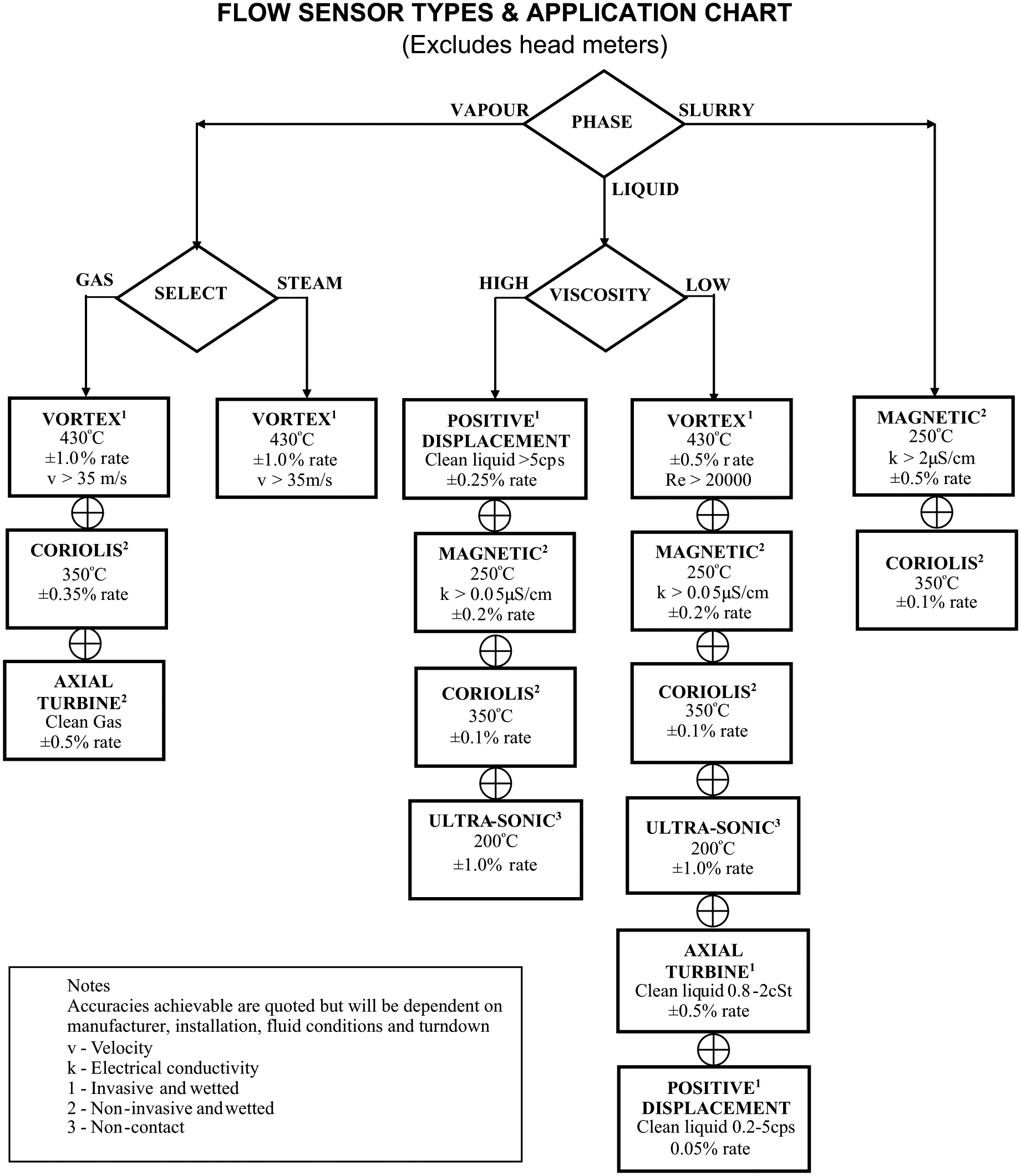
The chart below covers many of the non-differential pressure-type flow meters in common use. It gives selection criteria and various applications for each instrument: typical flow meter accuracies are shown as percentage of reading.
Footnotes
Acknowledgements
The authors wish to thank Mr Greg Livelli of ABB Instrumentation USA for permission to use material from his article ‘Flow metering theory and practice’.
Funding
This research received no specific grant from any funding agency in the public, commercial or not-for-profit sectors.