
Abstract
In this short review, we discuss the planned redefinition of the SI unit for electrical current, the ampere. We focus on the work National Physical Laboratory has been doing in this respect to develop a single-electron source capable of realising the new definition with the required precision.
I. Introduction
The ampere is one of the seven base units of the International System of Units (SI) and is defined as follows: The ampere is that constant current which, if maintained in two straight parallel conductors of infinite length, of negligible circular cross section, and placed 1 m apart in vacuum, would produce between these conductors a force equal to 2 × 10⁻⁷ newton per metre of length.
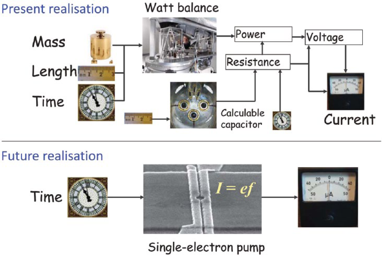
The definition is based on Ampere’s force law and also serves to fix the value of µ0, the permeability of free space. Due to the difficulty of performing accurate measurements of mechanical force, the ampere is no longer used as the starting point for electrical metrology. Rather the starting points are the quantum Hall effect and Josephson effect which are precise and reproducible standards of resistance and voltage based on quantum effects in semiconductors and superconductors at low temperature.1,2 The quantum Hall effect relates voltage to current with a constant of proportionality known as the von Klitzing constant, RK = h/e2, where the e is the elementary charge and h is Planck’s constant. The Josephson effect relates voltage to frequency via the Josephson constant KJ = 2e/h. These standards are often termed ‘quantum standards’ because their accuracy is grounded in fundamental physics, and is not dependent on details of material properties or details of the physical structure of the devices. Electro-mechanical apparatus such as the Watt balance and the calculable capacitor are needed to determine the values of RK and KJ in SI units (see Figure 1 top half). These experiments are arduous, and not routinely performed.3–5 This leads to the curious present situation that the units for voltage and resistance are maintained at a much higher level of accuracy than their values are known in the SI. The inconsistency will be resolved by adopting fixed values for h and e as explained by Mills (first article in this special issue). Then, the quantum standards will become the primary realisation of the SI units (see Figure 1 bottom half). At the same time, fixing the value of the elementary charge e also naturally leads to a new definition for the ampere which can be realised by transporting a known number of electrons through a circuit such that I = QS f, where QS = e and f is a clock frequency. We call a device which achieves this controlled electron transport, an ‘electron pump’. Achieving control of single electrons with the required speed and accuracy to realise such an ampere definition will be discussed in section III of this review.
Present and future definition of the ampere
Successfully making such an electron pump would give (a) a method of realising the new definition of the ampere, (b) allow us to test the consistency of the fundamental constants e and h involved in the three quantum electrical effects and (c) be of practical use as an accurate small current source. Small currents find use in a diverse range of applications but are difficult to generate accurately from a combination of resistors and voltages. Examples of applications are in radiation dosimetry, environmental monitoring, calibration of detectors for airborne particles and semiconductor wafer characterisation.
II. The Metrological Triangle
Given the exciting possibilities offered by electron pumps, it is not surprising that they have been the subject of numerous research efforts since the early 1990s. While National Measurement Institutes (NMIs) were motivated by the metrological applications outlined above, academic research groups were attracted by the prospect of studying the quantum-mechanical behaviour of electrons in an isolated, controlled way. Unsurprisingly, it quickly became clear that making a pump with metrological accuracy required a very detailed understanding of all aspects of electrical behaviour at the single-electron level.
Some important early results were achieved by a group at the National Institute of Standards and Technology (NIST) in the United States, led by John Martinis. They used a pump made from six metallic islands in series, each less than a square micron in area, and cooled to a temperature below 0.1 K in a dilution refrigerator. In the first experiment, they showed by direct measurement of electric charge that they could transfer electrons back and forth through the pump with an error rate less than 1 part in 108. 6 This type of error counting experiment is unique to electron pumps: no analogous experiment is possible for the quantum Hall or Josephson effect. It is possible because the same technology behind electron pumps can be used to make ultra-sensitive electrometers with a charge sensitivity orders of magnitude higher than what is needed to sense one electron. In the second experiment, the NIST group measured the extremely small (1 pA) current from their pump in terms of primary standards and showed that it was equal to ef to within the uncertainty of 0.92 parts-per-million (ppm).7,8
In isolation, this current measurement could be interpreted as a test of the pump accuracy. However, accompanied by the independent single-electron error measurement, it has also been interpreted as a ‘quantum metrology triangle (QMT)’ experiment,9–11 linking all three quantum electrical standards: the Josephson effect for voltage, quantum Hall effect for resistance, and the electron pump for current (see Figure 2 ). The QMT experiment measures the product KJRKQS, which should equal 2 (‘closure of the triangle’) if our understanding of the three effects is correct. (It is sometimes referred to as a test of Ohm’s law for quantum standards but one should remember that this is not strictly correct because the proportionality of current and voltage in the quantum Hall effect has no relation to Ohm’s law but instead is a consequence of electron motion resulting from the Lorentz force in magnetic field, although the mathematically form is the same.) The use of the Watt Balance in the redefinition of the kilogram assumes the correctness of the above simple equations for the von Klitzing and Josephson constants, so a QMT experiment is a crucial input to this redefinition.
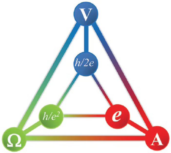
Schematic illustration of the triangle formed by the three quantum electrical standards, the Josephson effect, the quantum Hall effect and the single-electron pump. The inner triangle shows the associated fundamental constants
Independent measurements of RK and KJ constrain any possible non-closure of the QMT, and to provide new information, the QMT needs to be performed with an uncertainty of few parts in 107 and ideally 1 in 108. 12 This is also the required accuracy level for an electron pump to work as a standard of current. Unfortunately, pumps of the type studied by the NIST group are unlikely to reach this level, due to the extremely small current produced by the pump, itself a consequence of the relatively slow ‘tunnelling’ of electrons through the device. In fact, the current was too small to measure directly, and had to be measured indirectly, by charging a capacitor. A similar experiment conducted more recently at the Physikalisch-Technische Bundesanstalt (PTB) has reached a similar level of uncertainty, 13 and improvements in capacitance traceability may make it possible to reach around 0.3 ppm.13,14 However, a different pump technology is clearly needed to generate larger currents if pump experiments are ever to approach the 0.01 ppm level.
So far, we have not discussed the process by which a new standard replaces an old one. What kind of experiments do we need to perform on the new standard to be convinced that it is actually ‘better’ than the old one? Principally, we wish to test two properties of the new standard, its precision and robustness. Measurement precision is the closeness of agreement between measured quantity values obtained by replicate measurements on the same or similar devices under specified conditions. When comparing a new standard with the one it is replacing, the precision of the measurements is often limited by the performance of the old standard. For example, the precision of early measurements of the Josephson effect was limited by the performance of the Weston cells used to maintain the SI volt at that time. Likewise, as we shall see in section III, tests of the precision of the electron pump are limited by our ability to measure small current ratios. Of equal or greater importance are tests of the robustness of the new standard. Robustness is the property of a standard to deliver the same value if we make small changes to its operating environment, where the environment encompasses temperature, magnetic field, and the voltages used to control the device. These tests played a key role in the adoption of the Josephson and quantum Hall effects as they provide strong evidence of the fundamental nature of the physical effect underlying the standard. An even more powerful type of robustness test is to compare two samples of the new standard made from different materials, or with different geometry. For example, the quantum Hall effect has shown to be the same, to better than 0.1 parts per billion, in gallium arsenide and graphene, which are radically different materials sharing only the property that the conduction electrons are confined in two dimensions. 15 We can expect this type of test to play a key role in future research into electron pumps and their adoption as laboratory standards. We can also expect ‘error counting’ experiments to play some role, although as already noted, such experiments were not possible for the Josephson and quantum Hall effects and therefore are not strictly necessary for the adoption of a new electrical standard.
III. GHz Quantised Charge Pumping
In the last decade, the field of single-electron transport has become extremely popular with many research groups around the world pursuing different electron pumping technologies. Pekola et al. 16 have recently published an excellent review on the topic discussing all of the various pumping techniques from normal metal, superconducting, and semiconducting to hybrid pumps. One reason for the increased interest was the breakthrough of a new pumping mechanism with an unprecedented combination of accuracy and high speed operation. 17 This new mechanism was the result of a long-standing collaboration between National Physical Laboratory (NPL) and the Semiconductor Physics group at the University of Cambridge.
In the remainder of this short review, we will discuss the tuneable barrier pump which has been the main thrust of the NPL activity in this field. The original device consisted of a narrow wire etched in a high mobility GaAs/GaAlAs heterostructure on top of which a number of metallic gates had been fabricated (see Figure 3(a) ). By applying a combination of DC and AC voltages to a pair of gates, a potential profile can be created which allows for the isolation of a small quantum dot from the conducting leads (see Figure 3(b) ). Oscillating the potential profile of the entrance and exit gate with the correct phase shift will transfer a number of electrons from source to drain (see Figure 4(a) and (b) ). The key to the high-frequency operation is the fact that the entrance barrier can be lowered below the Fermi level in the source lead so that electrons can freely flow into the dot region without the need for the slow tunnelling processes which limited the speed of the NIST pump. The quantisation results from the fact that for a small quantum dot there is an energy difference between one and two electrons in the dot which results from their Coulomb repulsion. It was soon realised by Kaestner et al. 18 that the modulation of the exit barrier was not required to emit the trapped electrons from the quantum dot. The same action could be achieved by raising the entrance barrier higher, greatly simplifying the operation (see Figure 3(c) ). Figure 4(c) shows a ‘pump map’ which is a fingerprint of the basic pump operation.
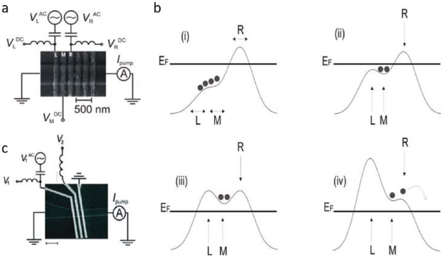
The tuneable barrier pump. (a) Scanning electron micrograph (SEM) picture of original pump design with radio frequency (RF) signals driving the entrance and exit gates of a quantum dot. There is also a plunger gate VM which can be used to tune the energy of the quantum dot. (b) Instantaneous potential profile relative to the Fermi level EF created by the gate voltages for four subsequent times in the pump cycle. (c) SEM picture of simplified tuneable barrier pump where only the entrance barrier is oscillated and no plunger gate
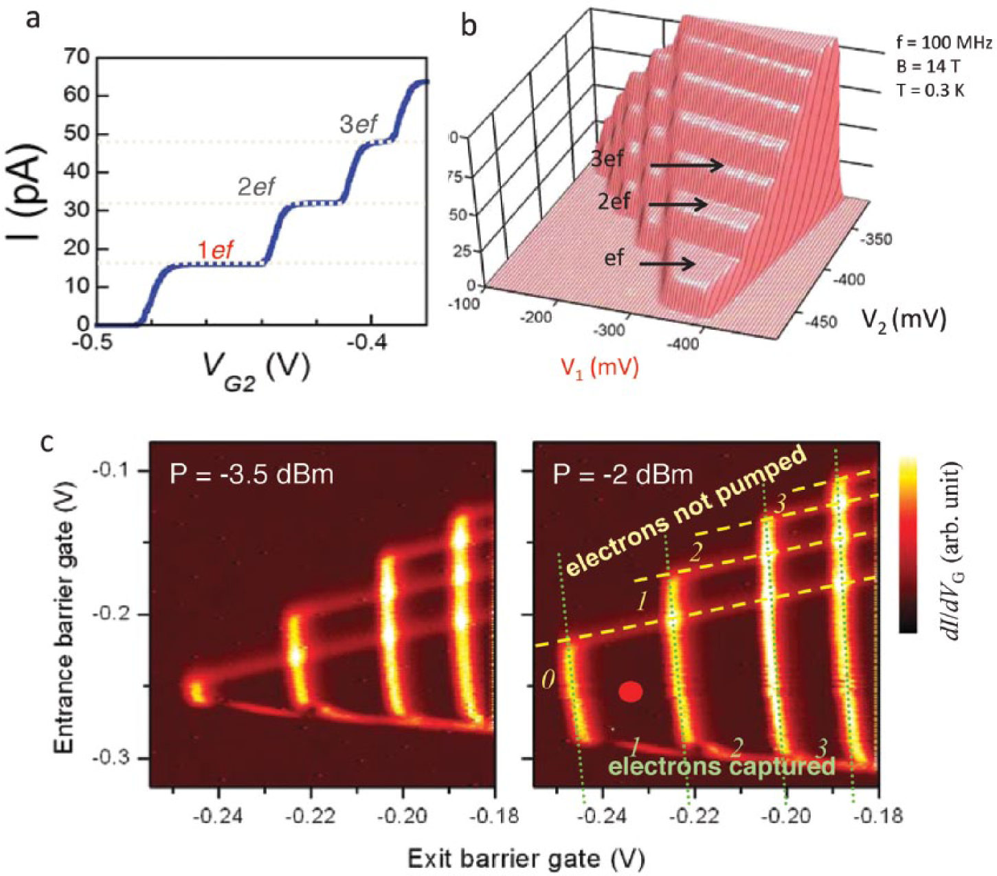
Quantised charge pumping. (a) Pumped current as a function of the dc voltage on the exit gate. (b) Three-dimensional map of pumped current as a function of both entrance and exit gates. (c) Pump maps obtained by taking the derivative of data such as displayed in (b) at two different radio frequency (RF) powers. The red dot indicates the point where the high-accuracy measurements are performed
This map is the numerical derivative of the pumped current versus entrance and exit gate barrier potentials (see Figure 4(b) ). Transitions in the number of electrons transported per cycle manifest as bright lines in the plot, and quantised pump plateaus are dark. The pump map gives us detailed information as to the mode of operation; how many electrons are trapped and transported forward, or remain in the dot and transported back to the source.
The original device had an accuracy of approximately 1 part in 104 at a pump frequency of around 500 MHz. 17 Two significant improvements in the last 5 years have pushed this uncertainty down to almost 1 part in 106. The first improvement was the application of a perpendicular magnetic field.19–21 As can be seen in Figure 5(a) , increasing the magnetic field substantially flattens the quantised current plateaus leading to a dramatic improvement in accuracy. To understand this behaviour, we first have to have some picture of the electron loading and unloading processes, governed by the tunnelling rates into and out of the quantum dot in the centre of the pump.18,22,23 In practice, the pump accuracy is determined by the tunnelling rates of excess electrons back into the source side of the device (the so-called back-tunnel rate) when the entrance barrier is rising rapidly at the moment before the dot becomes isolated from the source lead. This is the point at which unwanted excess electrons are shed, but the electrons to be pumped should be retained. This discrimination occurs due to the different tunnelling rates Γ n (t) for the nth electron out of the dot, which are determined by the shape of the confining potential geometry. The tunnel rate for one electron out of the dot should be very low and that for the second electron (and all others) out of the dot should be high to get current quantisation. We can adjust gate voltages and device geometry to try and maximise this difference in tunnel rates, but magnetic field can also play a role. At zero magnetic field, the electronic wave function is determined solely by the electrostatic confining potential. The penetration of the wave function into the confining barrier determines the tunnelling rates, and also the sensitivity of this tunnelling rate to barrier height. However magnetic field causes additional confinement, reducing the size of the electronic wave function and causing the tunnelling rate to drop sharply. It also rescales the sensitivity of Γ n (t) to the barrier height which enhances the effective ratio of tunnel rates. (This ratio, δ, of these tunnel rates δ = log Γ1/Γ2 is a very useful quality measure for electron pumps. 23 )
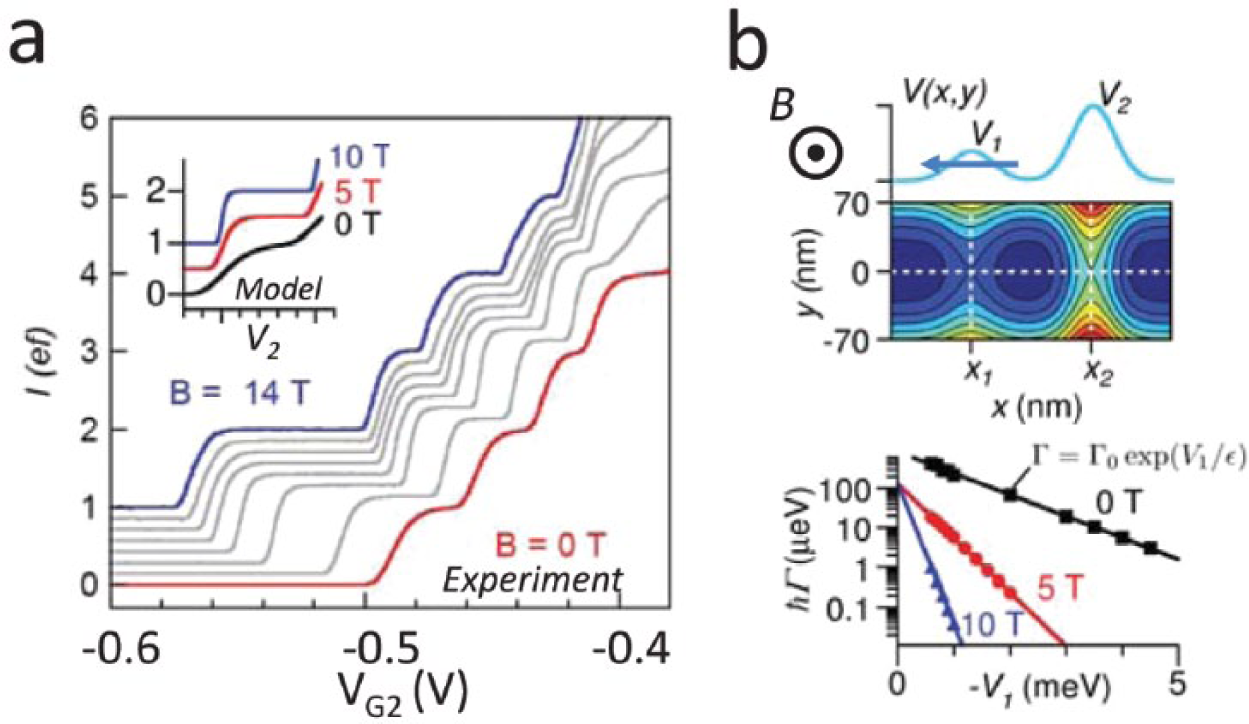
Magnetic field effect on tuneable barrier pump. (a) Pumped current for different values of applied perpendicular magnetic fields. Inset: calculation of quantised current using the tunnel rates determined from the model in computational model shown in (b)
This picture was confirmed by a detailed computational model performed by the group of Professor Sim at Korea Advanced Institute of Science and Technology (KAIST) in South Korea (see Figure 5(b) ). The figure shows the calculated tunnelling rates as a function of barrier potential for different perpendicular magnetic fields. Using these calculated tunnelling rates and the back-tunnel model, 23 the experimental data can be fitted rather well (inset in Figure 5(a) ).
The second major improvement was the use of specifically designed waveforms for the oscillating barrier. Increasing the pumping frequency to increase the current eventually fails, because the confining profile changes so quickly that the trapped electron can be excited to higher energy states in the quantum dot. 24 The back-tunnel rate for these higher states is very fast and current quantisation is lost. To extend the pump operation range to higher frequencies, we developed a technique using an arbitrary waveform generator (AWG) to generate a custom waveform that takes into account the time-dependent tunnelling dynamics. To design the waveform, first we note that for a sine wave drive ( Figure 6 ; black curve), most of the cycle time is used to raise the trapped electron over the exit barrier, and following ejection, lower the empty dot in readiness for the next cycle (phases 3, 4 and 1). Second, the increased error rate at high frequency is related to the rate at which the entrance barrier is raised during the early part of the pump cycle (phase 2). Our custom waveform is designed with a small initial dV/dt, speeding up for subsequent parts of the pump cycle ( Figure 6 ; red curve). The slow part of the custom waveform with repetition frequency f is approximately a segment of sine waveform of frequency f/5, enabling us to slow down the electron capture process by a factor of 5. Due to the exponential dependence of tunnel rates on barrier height, the factor 5 slow-down translates into several orders of magnitude improvement in accuracy. Figure 6 shows measurements of the current plateaus at two different frequencies for both sine and custom (AWG) waveforms; the difference in accuracy is dramatic.
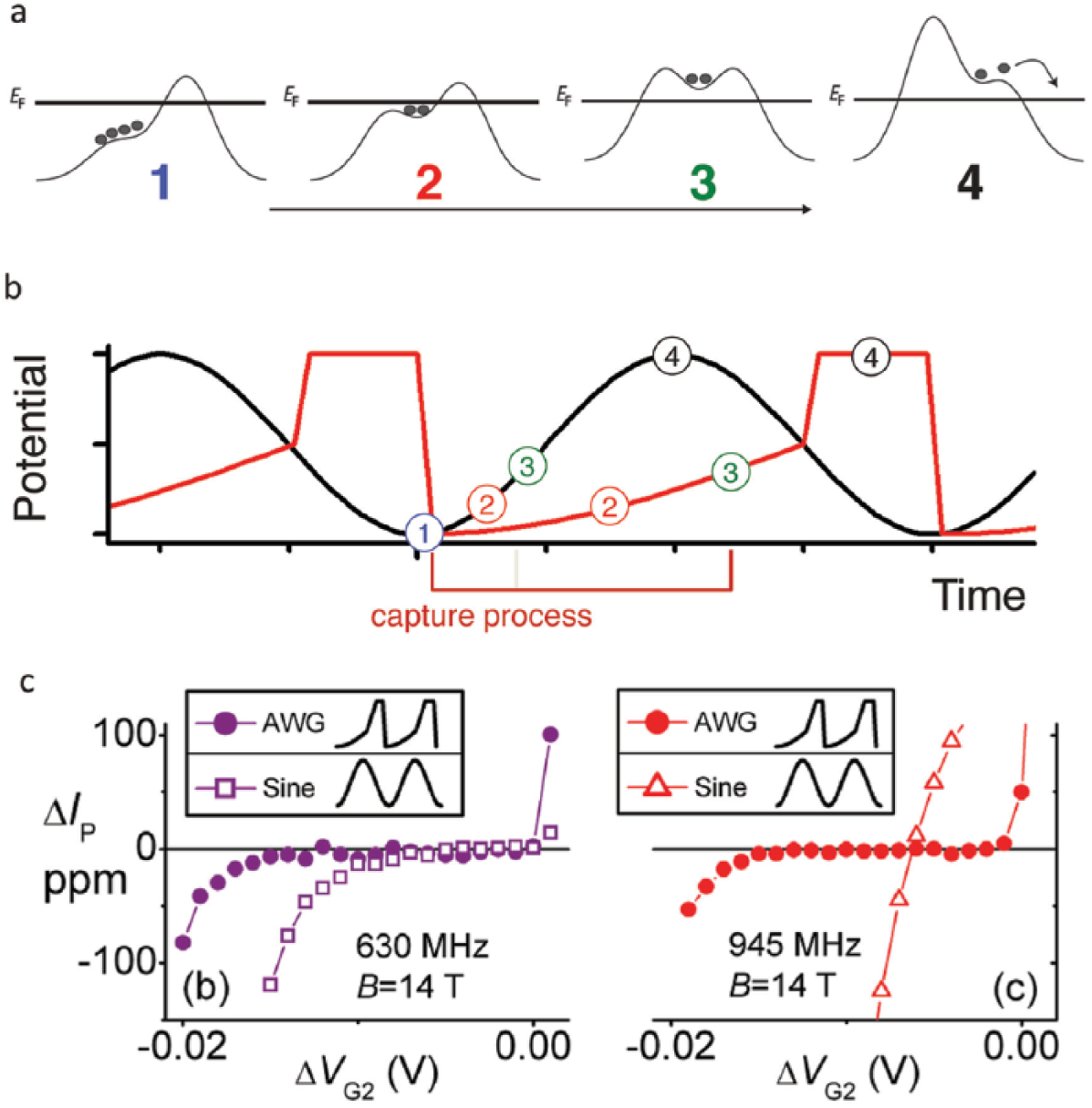
Effect of arbitrary waveform generator (AWG) waveform on pump accuracy. (a) Instantaneous potential profile relative to the Fermi level EF created by the gate voltages for four subsequent times in the pump cycle. (b) Black curve is the normal sinusoidal drive waveform used to pump electrons. Red curve is custom designed waveform which slows the electron capture process down during phases 1, 2 and 3 followed by a quick ejection of the electron in phase 4. (c) Effect of AWG pump waveform versus sinusoidal waveform for two different pump frequencies
IV. Accurate Current Measurements
The ideal method for determining the accuracy of a single-electron current measurement would be to measure the single-electron current directly against the quantum Hall and Josephson effects. This requires a current amplifier to increase the single-electron current of 150 pA by at least 4 orders of magnitude (150 pA × 104 × 12,900 Ω = 200 µV which is comparable with the voltage generated by a Josephson junction 25 ). The cryogenic current comparator (CCC)26,27 is the ideal method for this experiment because of its high absolute accuracy (the amplification gain is determined by a turns ratio with errors less than a part per billion). However, these CCCs are very difficult to fabricate and operate with the large turns ratios required to amplify sub-nA electron pump currents, and to date none have delivered a competitive measurement result.28,29 A more practical experiment is to use an indirect method via resistors and voltmeters calibrated against the quantum standards. At NPL, we did this by generating a reference current IR equal to the pumped current, IP, (see Figure 7(a) ) by applying a voltage VC across a 1 GΩ standard resistor R. 30 (The 1 GΩ is calibrated using a CCC but at a higher current than the single-electron devices can deliver.) A room-temperature current preamplifier with gain 1010 measured the small difference between the pump and reference currents. To remove offset currents and thermoelectric potentials, VC and VRF were synchronously switched on and off (see Figure 7(b) ). It can be shown that the dominant uncertainty in this method is the uncertainty of the 1 GΩ resistor which at NPL we can calibrate with 0.8 ppm systematic uncertainty (see Figure 7(c) ). Figure 7(d) shows a high-accuracy measurement of the current at 945 MHz drive frequency in 14 T magnetic field. The red data points in the middle of the plateau were taken over approximately 4 days of total measurement time and have a type-B uncertainty of 1.2 ppm which is at present the lowest uncertainty achieved for a direct electron pump current measurement. This result can be compared with the expected CODATA value of ef (blue dotted line). On the current plateau, the difference IP − ef is (−0.51 ± 1.2) ppm. The uncertainty can still be further reduced, to below 0.5 ppm, by improving the traceability to voltage and resistance.
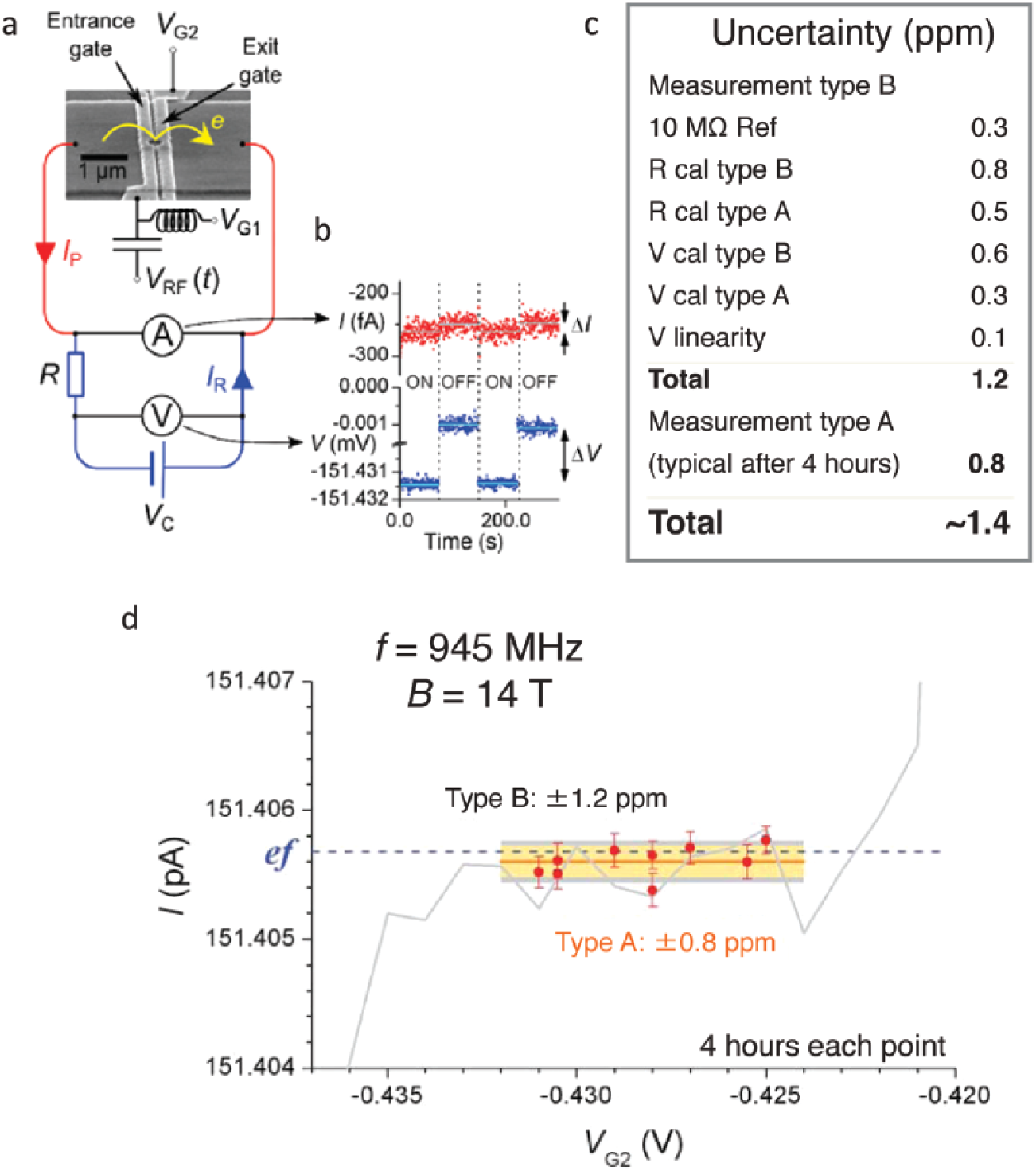
Measurement system and high-accuracy data of a single-electron current measurement. (a) Circuit used for accurate measurement of the pump current. The pump is depicted as a current source. (b) A short section of raw ammeter (red) and voltmeter (blue) data from a measurement run pumping with f = 945 MHz, showing the on–off cycles. (c) Total uncertainty budget for our measurement system. (d) High resolution measurement of the pump current as a function of exit gate voltage on the n = 1 plateau. Error bars show the systematic uncertainty. The horizontal dotted line shows the expected current corresponding to exactly one electron pumped for each pump cycle and the horizontal solid line shows the mean of the nine red points, with error bar indicating the systematic uncertainty
V. Forward Look
The tuneable barrier pump is a leading candidate for a primary current standard. It does not need dilution-refrigerator temperatures to operate, and works well at the temperature of 0.3 K reached with the pumped helium-3 cryostat. Theory predicts that the tuneable barrier pump can be as accurate as 0.01 ppm23,30 for a pump frequency around 1 GHz. In addition, it is possible to put many pumps in parallel to increase the current31,32 to increase the signal to noise in the current measuring experiment. In our opinion, there is a real prospect that the 0.1 ppm barrier can be broken in the next 5 years. Much work remains to be done, most importantly to demonstrate that the accuracy of the pump is robust against variations in the control parameters. Comparisons between pumps made from different materials (for example, silicon,33,34 gallium arsenide and graphene 35 ) and with different physical geometry will also give confidence that the pump mechanism is universal and not dependent on design specifics.
Going beyond the redefinition of the ampere, these high-performance single-electron sources can be used for studying quantum effects in the solid state akin to those already demonstrated for single photons.36,37 The statistics for electrons, which are fermions, is very different than those for photons, which are bosons, and this could lead to novel forms of interferometry and possibly quantum enhanced sensors. In addition, a single-electron source can act as a very pure and tuneable source of these fermion particles, and they could form part of a solid-state quantum computing scheme. In summary, the field of single-electron transport is buzzing with continuously improving accuracy which will soon rival the electron counting experiment and thus provide a realistic current source for practical applications in metrology.
Footnotes
Acknowledgements
We would like to thank our former colleagues, Mark Blumenthal, Bernd Kaestner and Sam Wright, our collaborators in Cambridge, John Griffths, Geb Jones, Ian Farrer and Dave Ritchie. A special thanks to Mike Pepper for his continued interest in our work.
Authors’ note
For permission to reuse this content, please e-mail the NPL Copyright Officer at
Funding
This work was supported by various programmes of the National Measurement System (NMS) and European projects Ampere and REUNIAM.