
Abstract
The paper presents the development and application of measurement and control devices and control information systems in coal mines with underground exploitation. The locations of units for measuring the concentration of methane, carbon monoxide and oxygen; the control of short circuits on ventilation doors; the control of main fan depression and the airflow speed are proposed. As a result of the research, the structure of control information system in Senje mine and ergonomic analysis of measurement and control devices in this mine are presented. Further modes of development of control information systems in underground mines in Serbia and solutions for their reconstruction are proposed.
I. Introduction
Underground coal mining has long and successful tradition in many countries. Coal mining is important in the developing countries to meet the energy demands. In the course of history, the development of technology brought about different methods of underground coal mining: longwall mining, continuous mining, room and pillar mining, blast mining, shortwall mining and retreat mining. Selection of the most appropriate mining method is a complex task. 1 The main goal in coal mine industry is to achieve higher quality of extracted ore, to increase the production and to reduce the costs of extraction.
Underground coal mining is one of the most dangerous occupations in the world.2–5 In Asfawa et al., 6 the authors examine whether the profitability of underground coal mines is associated with the rate of occupational injuries and fatalities. Some authors propose factors and indicators that affect the high number of accidents, injuries and fatalities in underground coal mines: small size of mining environment, specific operating and safety conditions, dangerous methods of mining, inadequate workers’ experience and training, lack of adequate investment in safety system, unpleasant working conditions, inadequate safety standards and laws, and lack of previous experience with emergency situations and disasters in mines.7–11 An in-depth review of occupational health hazards in mines is presented in Donghue, 12 along with the description of physical, chemical, biological, ergonomic and psychological hazards.
The problem of safety in underground mines is still important, with respect to management and practical implementation. The safety performance is important in the mining industry because of the complexity of the process and bad work conditions, especially in underground mines. Maintenance is crucial for the technical part of the production system, and maintenance performance measurement has not been sufficiently applied in the mining industry. 13 The number of accidents in coal mines around the world, especially in mines with underground exploitation, is still high. The high risks are influenced by the size, uncertainty, complexity, high costs and dangerous mine working environment. 14 During the previous century, more than 10,000 workers died in gas explosions only in the US underground coal mines; the number of fatalities has been decreased, but the number of accidents (explosions and fires) is still relatively high.15,16
To achieve higher level of safety, monitoring and control systems for workplace indicators and technological processes have been introduced. The effects on the environment and workers’ health cannot be ignored. Behaviour-based safety systems, risk management and monitoring of workplace conditions can significantly improve the efficiency of the safety systems in underground coal mines.15,17,18 Pandit and Rane 19 describe the design of the system that collects different environmental indicators from underground coal mine. Atmospheric monitoring systems (AMS) allow operators to monitor real-time atmospheric conditions in underground locations from where coal is extracted.15,20 Zhou 21 proposes coal mine safety monitoring system based on general requirements regarding coal mine safety. The effects of the mine safety monitoring and control system on the prevention of accidents caused by mine gases and fires in underground coal mines, and the structure of the mine monitoring and control system is described by Sun. 22 Distance monitoring and equipment control can help to prevent large accidents and coal production problems. Sensors usually detect the concentration of methane (CH4), carbon dioxide (CO2), carbon monoxide (CO), oxygen level (O2), air temperature, temperature of the mass (ground), the speed of intake and return air, atmospheric or differential pressure, relative humidity, dust concentration in the air, the state of ventilation doors and the concentration of additional gases that can be dangerous at specific mines. The main problem in Serbian coal mines is the methane released during and after mining operations, usually called coal mine methane (CMM). Machine learning methods can be applied for the prediction of methane concentration in an underground coal mine. 23
All remotely monitored data are transferred to control room. Ergonomic requirements were not defined during the development of control centres (CCs) in Serbian coal mines, and it was necessary to perform further research on compliance among operators and process control elements in CCs.24,25 Completely new structure of operators’ activities required detailed analyses, with emphasis on the human factor in control and monitoring systems, the influence of operator on the performance of control systems and the impact of high operator’s mental workload on the quality of the operator’s performance.26–28 The operator’s location is in the control information system (CIS), where all underground operations are monitored and controlled. This significantly expanded the job of operators, especially in emergency situations, when the problem with overloading became very important.27,28
Adequate communication within an underground mine, as well as among CC and underground worksites, is the most important for efficient everyday functioning and safety. Wired communication enables transfer of huge amount of data at a high data rate through standard or optical cables, but this type of communication is problematic during the emergency situations (during the roof falls, power failures, fire or explosion), when alternative communication channels could be helpful in underground mines. 29 Different ways of communication in mines, wired and wireless, are presented in the studies by Patri et al., 29 Schiffbauer and Brune 30 and Bondyopadhyay et al. 31 In recent times, plenty of studies have been focused on the use of wireless technologies for communication in underground coal mines.29,31,32
Some problems with environmental monitoring in narrow and long underground tunnels, the definition of measurement locations, sampling density and the number of sensing devices are analysed by Li and Liu. 32 Different methods of automation of the production and transportation are introduced in underground coal mining systems, in order to increase the efficiency of coal mining and to protect workers. The use of diesel fuel influences underground air conditions, and monitoring of ventilation system becomes even more important.33,34 Therefore, the emergency control of technological environment and robust software control of the electric machinery activity in coal mines are needed.35,36
The next step in the development of CIS in underground coal mines is the introduction of teleremote systems. 37 The introduction of these systems can provide significant improvement in mine production performance and safety of workers who are removed from the most dangerous locations in the pit during the extraction of coal. Baiden 37 proposes solutions for improving mine operating centre that enables distance control of different machines used in coal production process in several underground coal mines simultaneously.
There is no single solution for the creation of CIS that can satisfy the requirements for all underground coal mines. However, monitoring of working conditions in the most important underground locations and the state of machines, power supply and ventilation units, collection of data from the remote substations, and effective and durable communication system are important for increasing both safety and productivity of coal mines. This paper presents the solution regarding CIS implemented in Serbian underground coal mines. The paper is organized as follows. In this ‘Introduction’ section, the importance of the development of control devices (CDs) and CISs in underground coal mines is described. The ‘Methodology’ section describes the measurement of parameters and CDs developed for the purpose of measurement. The ‘Results’ section describes the implementation of CCs and ergonomic analysis of CDs in a pit. The ‘Discussion’ section contains the discussion on advantages and disadvantages of the system implemented in Serbian underground coal mines, as well as the suggestions for further improvement. The ‘Conclusion’ section consists of concluding remarks.
II. Methodology
A. Measurement of parameters
The measurement of the concentration of methane (CH4) in the air in a pit is the most important. It is measured with the aim to determine whether the concentration of methane in a particular part of the pit is within tolerable limits. The concentration of carbon monoxide and oxygen is measured in order to detect endogenous fires in their early stages and in order to protect the pit workers. On the basis of the data on the concentration of carbon monoxide and oxygen deficit, it is possible to detect endogenous fire in early phase. Detection of oxygen concentration is important for the accuracy of measurement of methane concentration with catalytic sensors. Based on the airflow speed in rooms with flow-through ventilation, and with the known profile of the room, volumetric flow can be approximately measured. In rooms that are separately ventilated, volumetric airflow is measured through the airflow speed in pipes. Based on the known speed and known cross-sectional area in which the speed is measured, we determine the volumetric airflow through the tube, which also determines the volumetric flow through this room. Finally, based on the known volumetric flow rate and known profile of the room, it is possible to determine the speed of airflow in this room, in order to determine its adequacy for preventing stratification of methane. Besides, differences in pressures on ventilation doors and depression of the main fan are also measured. Based on the difference between pressures on ventilation doors, short circuits in ventilation network and the accuracy of ventilation and fire protection doors are controlled. In addition, based on the depression of the main fan, safety and quality of ventilation system are controlled.
In order to fully comply with the adopted technical requirements, CDs must have the following minimum characteristics: 24 continuous measurement and low power consumption; the possibility of presentation of measured values directly on measuring devices; analogue output for transmission of information to remote location; setting alarm thresholds on the device itself, light or sound alarm for signalling the situation when the set alarm threshold is exceeded; the power supply from the pit electricity network by means of intrinsically safe power supply device; automatic switch to backup power supply from its own battery after the power supply interruption; the possibility of testing its own battery for backup power supply; the possibility of testing the alarm signal and the realization of the type of explosion protection with intrinsically safety category ‘ia’.
In addition to these features, instrumentation for measuring the concentration of methane and airflow speed in pipes for separate ventilation need to have the possibility of automatic disconnection from electrical power network in affected mine pit rooms where the measured values exceed the pre-set alarm thresholds for methane and airflow speed.
For timely notification of underground workers from the control and management centre and transmission of voice messages from the pit to the centre, it is necessary to use alarm voice system units in the pit with the following technical characteristics: 24 transmission of voice messages from the centre in both directions along the underground rooms, accepting voice messages in both directions in the pit at a distance up to 50 m if the unit is activated from the centre, the possibility of calling from the pit by activating the units by the miners, the possibility of transmission of alarm messages from the pit, the power supply from its own battery that is recharged from the centre and the realization of the type of explosion protection for intrinsic safety.
Collecting signals from the measuring devices should be done with the help of underground units of the transmission system (substations). Substations should have the following technical characteristics: the acceptance and processing of analogue signals from the measurement device, transmission of data in digital form over a common transmission line from many substations to the CC, low power consumption for simultaneous supply of several substations from the CC with the same intrinsically safe power line and the realization of explosion protection for intrinsic safety category ‘ia’ and moving into the pit without any pre-setting.
B. Description and location of CDs in the pit
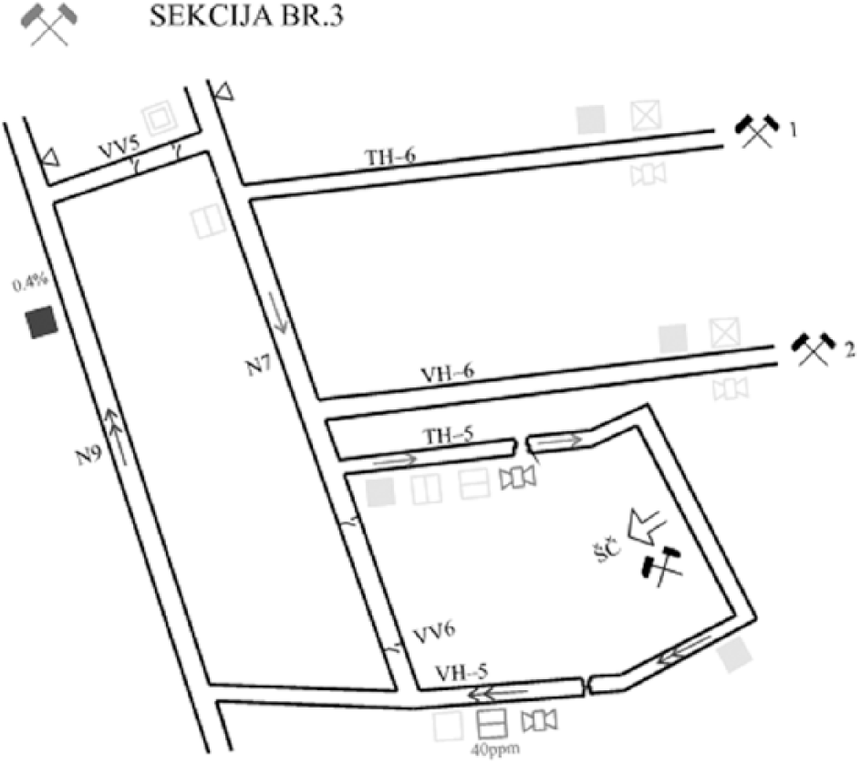
Based on the previously mentioned technical requirements and technical characteristics of CD, appropriate devices are selected and installed in mines Rembas, Soko and Jaran Do on the basis of mining projects. The principle method for deployment of CD in the pit is shown in the example of Senjski mine, one of the mines from the ‘Rembas’ system.
The concentration of methane is measured with the BM-3 device ( Figure 1 ). In Senje coal mine, the project envisages the installation of 11 BM-3 devices in order to control the following:
Aggregate output airflow of a longwall excavation area and a room-and-pillar excavation area;
The main output airflow, just below the ventilation hole;
Common output airflow from a longwall excavation area and separate ventilation of preparation site for ventilation and transport corridors;
Separate ventilation of the preparation area (worksite) for creation of the wide transport corridor (TH-6);
Separate ventilation of the preparation area for creation of the wide ventilation corridors (VH-6);
Inlet airflow from longwall excavation area;
Output air stream directly from a longwall excavation area;
Output airflow from the room-and-pillar excavation area;
Separate ventilation of the preparation site;
Output airflow from the preparation area for room-and-pillar excavation; Common output airflow from the preparation area for room-and-pillar excavation.
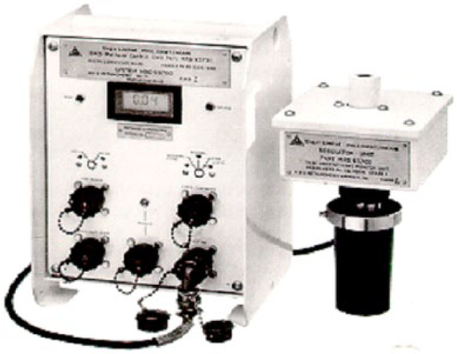
BM-3 device
The concentration of methane in working areas for room-and-pillar excavation is not controlled via a remote control system. Due to lack of space, lack of optimal location of measurement devices and the constant danger of breakage, remote control would not be reliable. Therefore, the concentration of methane in the working areas of excavation is measured with portable measurement devices.
The concentration of carbon monoxide (CO) is measured by BCO-1R device ( Figure 2 ). The project envisages measuring the concentration of CO in six places in order to control the following:
Inlet airflow of both areas (an area with longwall excavation and an area with room-and-pillar excavation). This control is necessary because of the long conveyor belts in areas N-1 and N-4, and the eventual approach of carbon monoxide in the air at the surface;
The main output airflow from pits;
Inlet airflow of longwall excavation area, which also controls relatively long transport line N-7;
Output airflow from longwall excavation area (based on the difference in the concentration of carbon monoxide at the entrance and exit, endogenous fires in the longwall excavation area are detected);
Entry airflow for areas with room-and-pillar excavation, which enables control of all transport routes to the entrance of the mining area;
Output airflow for areas with room-and-pillar excavation (based on the difference in the concentration of carbon monoxide at the entrance and exit, endogenous fires in the area are detected).
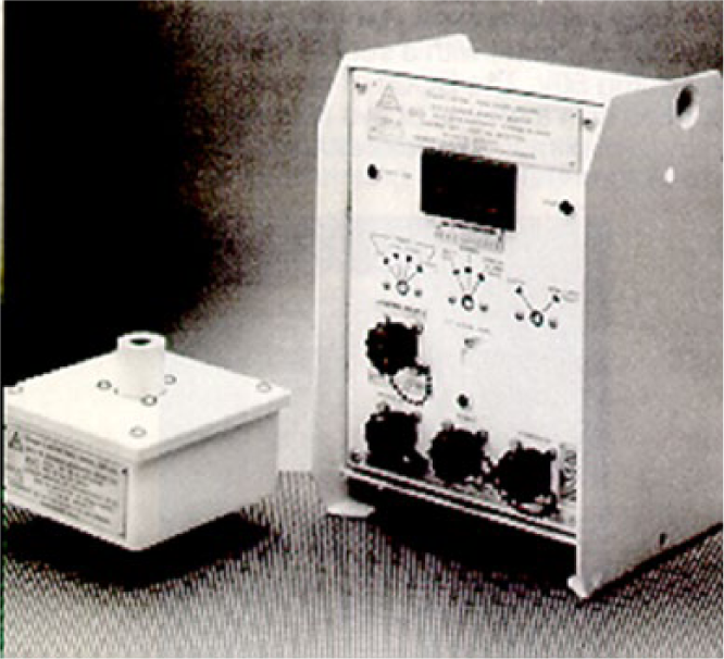
BCO1-R device
The concentration of oxygen is measured with BO1-R device ( Figure 3 ).
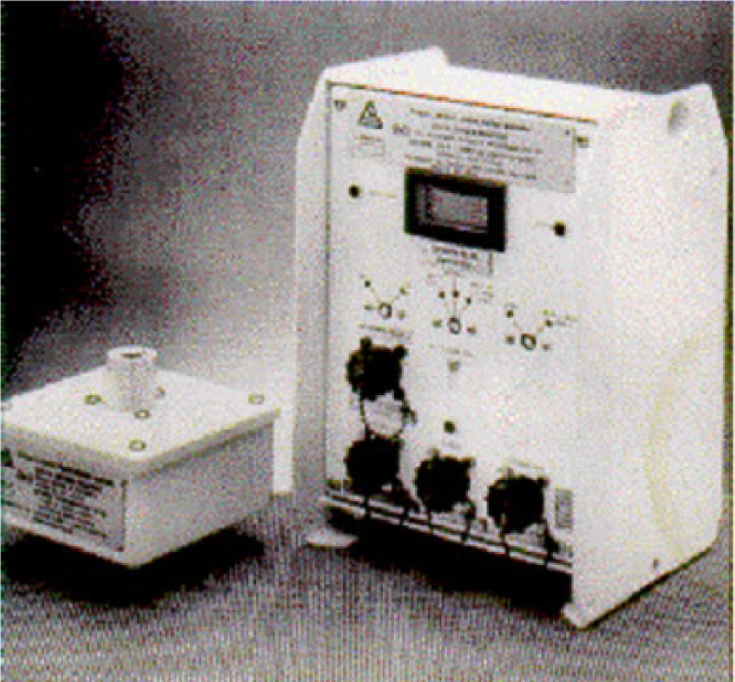
BO1-R device
The concentration of oxygen is measured at three locations, in order to control the following:
Output air stream from longwall excavation area (based on the oxygen deficit and the carbon monoxide concentration, it is possible to detect endogenous fire at longwall excavation area in early stages);
Inlet air streams in room-and-pillar excavation areas;
Output air streams from room-and-pillar excavation areas.
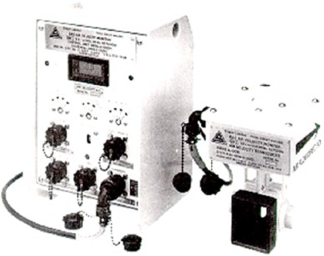
The control of short-circuit on ventilation doors and depression of the main fan (ventilator) is performed with the help of BP-2 device ( Figure 4 ).
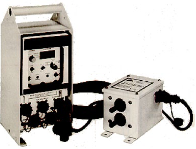
BP-2 device
The control of short-circuit on ventilation doors (DP) is performed at the following four measuring points:
Ventilation doors VV-1, VV-2 and VV-3;
Ventilation door VV-4;
Ventilation doors VV-5 and VV-6;
Ventilation door VV-7.
Control of depression of the main fan is performed directly on the ventilation facility. BA-5 device is used for measuring the airflow speed ( Figure 5 ). The speed of airflow is measured at six locations in order to control the following:
The main entrance airflow;
The main output airflow, just below the ventilation hole;
Airflow in N-7 path behind the VH-10, which controls the total quantity of air that is used for ventilation of VH-6 and TH-6 preparation worksites, and a longwall excavation area;
Airflow in the TH-5, which controls the amount of air that is used for ventilation of a longwall excavation area;
Air stream in the U-4 rise, which controls the total quantity of air that is used for ventilation of room-and-pillar excavation area and preparation areas no. 3 and no. 4;
Airflow in the TH-3 area, in front of the fan for separate ventilation of work areas no. 3 and no. 4. The difference in the amount of air at the measuring point 5 and the amount of air at the measuring point 6 defines the amount of air which is used for ventilation of a room-and-pillar excavation area.
BA-5 device
The same principles for the deployment of CD are implemented in other pits of Rembas mine complex (Jelovac, Strmosten and Pasuljanske livade).
III. Results
A. Implementation of centres for control
In the Serbian coal mines ‘Rembas’, ‘Soko’ and ‘Jaran Do’, CISs were built. Figure 6 presents the structure of CIS Ei SM-64 in ‘Soko’ mine.
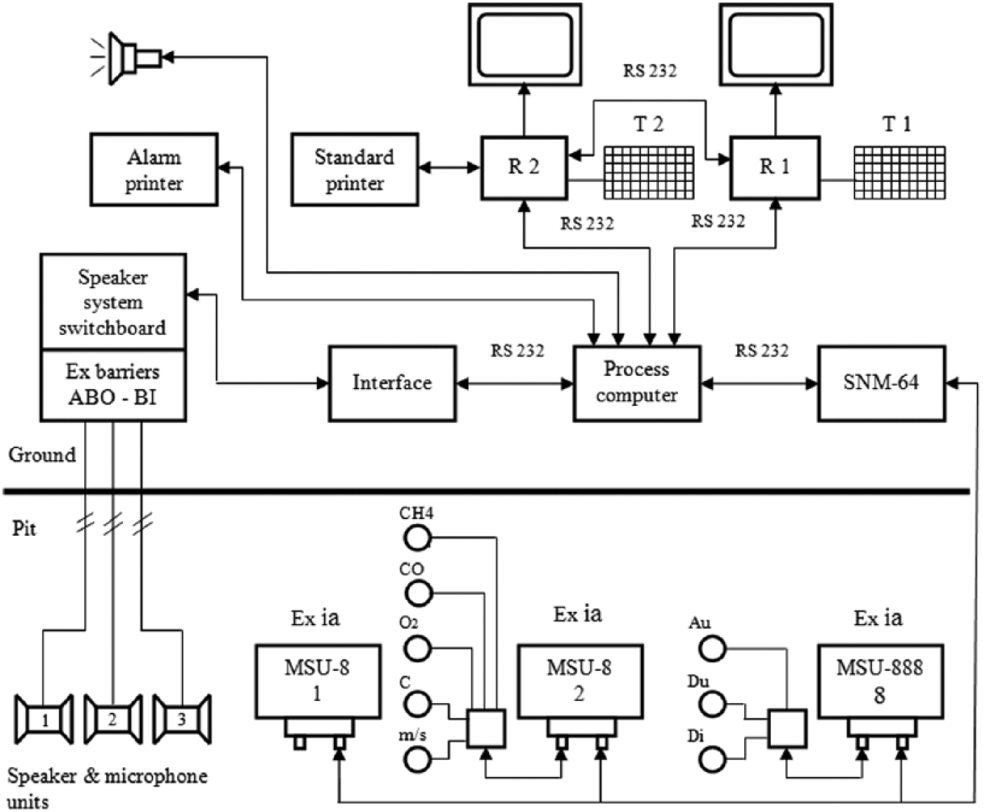
The structure of Ei SM-64 system
The equipment in CIS in ‘Senje’ coal mine is designed to provide a clear and distinct permanent display of current values of ventilation, gas and fire alarm parameters and the state of the alarm-speaking sub-system; to display the state of all parameters and elements right before the alarm and during the emergency situation; to save all current data and data about alarms; to print data about alarms during the emergency situations and to print reports based on processed data (diagrams, tables, alarm images, etc.). The equipment consists of the following:
Control desk with the main computer R1 and additional computer R2, system keyboard, equipment for recording conversations in alarm situations, two colour monitors, printer for reports, keyboards for R1 and R2 computers, and alarm printer;
Synoptic maps;
Additional equipment consisting of processing computer; multi-channel intrinsically safe interface SNM-64, through which all intrinsically safe digital and voice communication is performed; electronics covering the pit; and other necessary equipment.
B. Ergonomic analysis of CDs in a pit
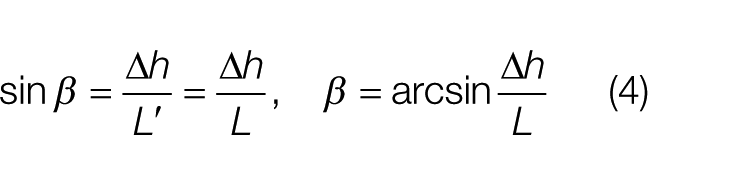
The specification of CD shows that the measurement results in all devices are displayed on liquid-crystal display (LCD). The background is grey, and the numbers are black. The size of characters (digits) is 10 × 5 mm2. The digits are presented by seven segments. It is interesting here to determine the optimal distance of observed LCD and mounting height of CD. This analysis is based on the ergonomic recommendations for the angular dimensions of visual signs: from 18′ to 20′ for an accurate reading or from 35′ to 40′ if a speed of reading is needed along with accuracy, which is present here in emergency situations. For the determination of the angular dimensions, the following equation is used 38
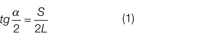
where S is the height of the character on LCD and L is the distance of the viewing angle height from the LCD, taking into account the condition that the LCD is set vertically, and the imaginary line that connects the eye and the LCD makes with LCD the angle of 90°, that is, divides S into two halves ( Figure 7 ).
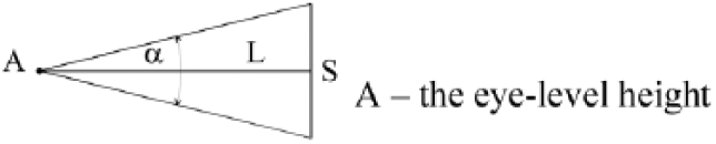
Determination of the angular dimension of visual signs
According to equation (1), it follows that
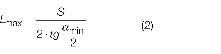
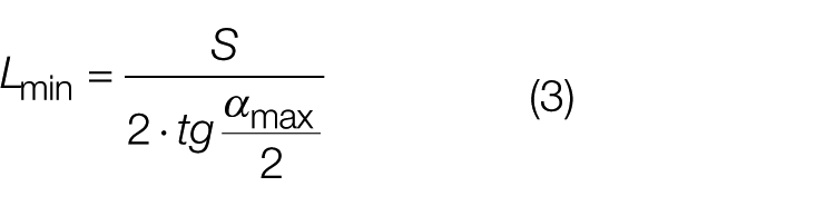
For αmax = 40′ and αmin = 35′, it can be obtained that Lmax = 0.982 m and Lmin = 0.859 m. These are the real conditions of distance readings in the pit, and the height of signs meets the ergonomic recommendations. However, in practice, there are many cases when it is impossible to set the device to a height equal to the height of point A and vertically, that is, as it was previously mentioned. In these cases, the devices are usually installed at a height (H) that is higher than the height of the point A. In this case, the displacement angle (β) for CD or LCD in the vertical plane must be determined.
To determine how β angle depends on the height of the LCD, we use the configuration presented in Figures 8 and 9 . Figure 8 shows the angular position of the device, whereas Figure 9 presents an equivalent triangle for determining β angle.
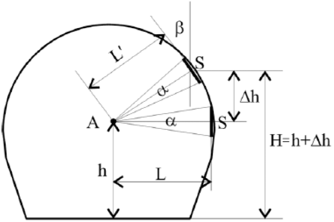
The location of CD in a pit hole
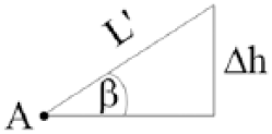
Equivalent triangle
In practice, the devices are placed at heights (H) ranging from 1.6 to 2.2 m. For that range of heights and the value of Δh from h (1.6 m) to Hmax (2.2 m), it can be taken that L′ = L.
According to the equivalent triangle ( Figure 9 ), it follows that
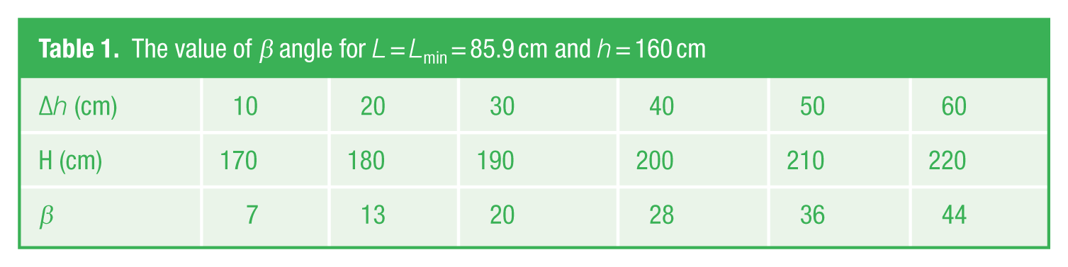
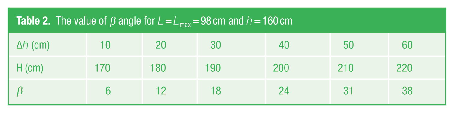
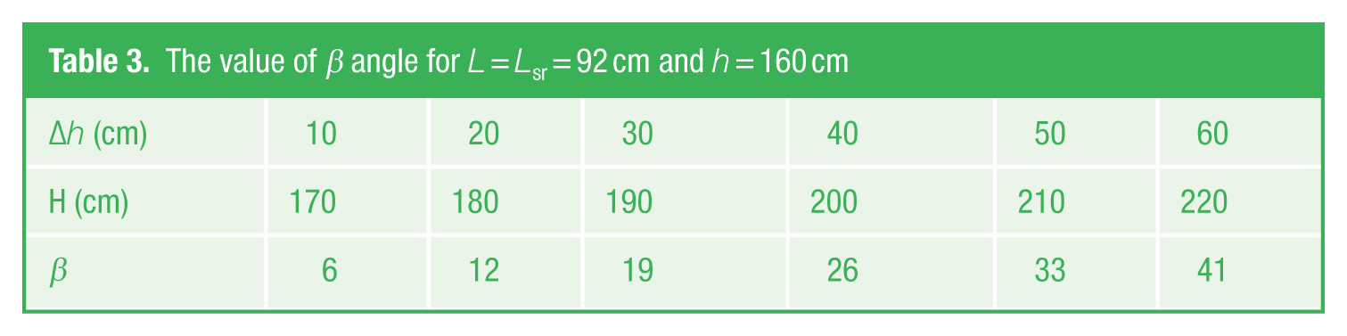
Tables 1 – 3 present the values calculated for β angle, based on Δh and height H, while maintaining the installation conditions for the angular dimension of visual signs.
The value of β angle for L = Lmin = 85.9 cm and h = 160 cm
The value of β angle for L = Lmax = 98 cm and h = 160 cm
The value of β angle for L = Lsr = 92 cm and h = 160 cm
For β angle of CD placement, there are the same conditions for reading from LCD from the point A as when CD is positioned vertically (β = 0). However, the conditions are not totally the same. This refers to the angle of seeing the display on the vertical plane.
Based on the data from the previous tables, it can be seen that for the mounting height of up to H = 190 cm for CD, LCD can be read only by moving the eyes, and for the height from 1.9 to 2.2 m, one should move up ahead.
IV. Discussion
The information in CIS is displayed in two ways:
Real-time information is constantly available to the operator at the monitor of the R1 computer and allows centralized and continuous review of events in the pit enabling timely identification of incurred or potential emergencies.
Displaying the processed data is done in the form of a diagram resizing parameters measured for 1 h, 8 h, 24 h or at user’s request and in the form of tables. This representation allows that technical care and service pit ventilation units analyse the conditions in the pit in terms of ventilation, the presence of methane and causes of this presence, the presence of carbon monoxide that can be an indicator of fire danger and other analyses. The display in real time is shown in Figure 10 , whereas Figure 11 shows display in the form of a diagram.
The real-time data presentation
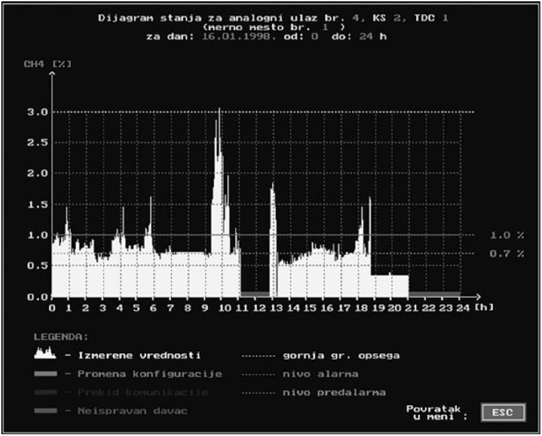
Monitoring the change of methane concentration
Illustrating the effectiveness of this type of display in alarm situations leads to the conclusion that we should continue to develop mode, shape and form of presentation. The research was conducted by collecting the opinions of the responsible operator and technical personnel mines, the own investigation and analysis of the data recorded and processed during an accident in the mine ‘Soko’, caused by inflammation of methane.
Figure 11 shows the diagram of changes in methane concentration at the site of methane inflammation. It can be seen that until 19 h, the concentration was variable and that it reached the value of the alarm and pre-alarm threshold. From 19 to 21:04 h, when the inflammation of methane started, it can be seen that the apparent concentration was about 0.4% for CH4. The concentration was actually much higher, which can be proven by diagrams showing changes in methane and registered by CD for methane measurement placed near critical CD. The current system is not able to alert the operator that something like this happens. The problem can be identified only if the operator pays attention only to that device. However, there are some pre-alarm signals and alarm signals from other devices, and the operator must pay attention to those alarms. This shows that the described state diagram illustrated in Figure 11 should have a warning effect, for example, blinking yellow symbol for devices, according to ergonomic guidelines. In that situation, one part of the display monitor of R1 computer should be allowed to present the diagram taken up to that point, and it would very clearly display to the operator that something goes wrong with that CD. The analysis of the method of processing data in R1 computer proves that this is not hard to implement because these data are in memory, and drawing program can easily be transferred from R1 to R2 computer, or a diagram can be drawn in R2 computer, returned to R1 computer and displayed on the computer monitor.
Previous observations indicate that for quick comparison of diagrams representing changes in the concentrations of several parameters, it is more suitable to display multiple diagrams simultaneously. The monitor of R2 computer presents only one diagram at this point. The reality arising from the practice of scheduling CD at worksites shows that it is useful to show up to four diagrams or pictures at the same time. The image size in this case would be as shown in Figure 12 . The scale on both axes, for parameters and time, would remain the same. The assumption in this case is that four parameters of the same type (e.g. methane) are presented because in this case the CH4 axis values are of the same scale since the measuring range of all CD for methane is 0%–3%.
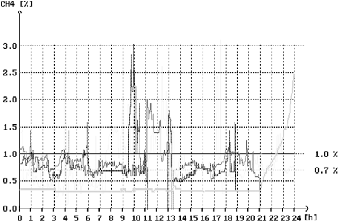
Displaying multiple diagrams of methane concentrations from different CDs
In order to distinguish which diagram refers to which measuring point, we introduce four shades of yellow and label them with numbers or letters or four different colours. All these devices may have the same or different alarm or pre-alarm thresholds. If they are equal, we have the purple line for pre-alarm threshold, red for alarm and blue for the upper limit of the range. If they are different, then each device must have its pre-alarm and alarm value and upper limit of the range, that is, lines again in some shades of purple, red and blue colours to achieve consistency in the application of colours.
It is necessary to draw the line beside the ordinate, whose segments are presented with different colours and denote certain irregular conditions such as changes in configuration (moving a device), breakdown in communication and a faulty sensor or CD.
In order to study the display, the current program is modified in order to enable further modes of displaying information in the form of diagrams. The final assessment is then based on the analysis of processed and presented materials based on actual data. Further analysis must deal with the way of thinking of operators who watch display in real time, as well as with the reviews of the technical staff performing data analysis in offline mode.
Each of these irregularities has detailed descriptive explanation, and operator can completely understand it. In case of the diagram with a single figure, there is a problem of clear identification of which CD has identified the irregular state. To overcome that, these lines have to be appropriately marked as diagrams. It is not difficult to conclude that this type of display information requires operators to employ additional efforts to quickly and accurately interpret the display. One good side of this display is quick comparison of concentration changes on the diagram for different CD in a different point in time. Simultaneous display of diagrams, without labelling thresholds and irregular situation, is illustrated in the simulation presented in Figure 12 , based on actual data rather than programmatically drawn diagrams, because the current software package does not support this way of presenting information. In order to further develop the method of displaying information, the current program must be further updated so as to enable data display in the form of diagrams and to make a final assessment on the basis of actual data. During the analysis, opinions of operator who watch the display in real time and the technical staff who perform data analysis in offline mode should be considered.
V. Conclusion
The increasing demand for energy has led to the intensification of resource exploitation in underground coal mines. The increase in production has been followed by the work on the deeper excavation. Greater depths worsen working conditions, which specifically refers to the effective ventilation of roadways and maintenance within tolerable limits of ventilation, gas and fire parameters, which are the main indicators of quality of working environment in the pit, and alarm or normal state of working conditions. Therefore, this paper has presented detailed analysis of the development, selection, implementation and deployment of control and measurement devices, along with the practical application in Senje coal mine. We have presented the results of an ergonomic analysis of special measurement and CDs and ergonomic recommendations for the placement of these devices in underground coal mines.
Centralized representation and processing of information in real time on ventilation, gas and fire parameters stand for the most effective protection of people and equipment. The concentration of all relevant data in one place enables operators to make the right and adequate decisions, which also allows the possibility of timely interventions to prevent alarm and emergency situations. This caused the introduction of CISs working in real time, whose main task was to provide a centralized, continuous and detailed overview of the situation; to inform pit workers on time about the dangers in parts of the mine that are endangered and to clearly monitor the development of phenomena in the pit, which is especially important during the recall of pit workers from parts of the mine where emergency situation happens. This paper has described the concept of implemented CIS and details about information display modes with the analysis of the advantages and disadvantages of different data representations.
Technical capabilities of CIS are used by human operator, and he or she is responsible for taking appropriate actions based on the information about the events in the mine pit. This concept of CIS in the coal mines, and operators’ tasks arising from its application, clearly indicates that this is not a one-sided issue related to assessing only work activities, responsibilities and capabilities of operators in CCs, but to his or her complex communication with CIS.
Footnotes
Funding
This research received no specific grant from any funding agency in the public, commercial or not-for-profit sectors.