
Abstract
Comparison of measurements may be used to allow early detection of measurement system faults, with the potential to reduce production losses and enhance protection function integrity. Automatic comparison and alarming can be implemented in a simple manner using conventional function block capability as typically available within distributed control systems. An outline of the functioning of such a system is described, together with details of how credit may be taken for deployment of such an alarm when performing protection function probability of failure on demand calculations.
I. Measured Variable Comparison Alarm Approach
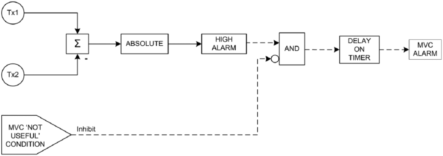
Where more than one measurement of the same process variable is available, typically one associated with control and one with a trip function, it is possible to compare the measurements to establish a degree of confidence that the sensor subsystem associated with the trip function has not been compromised. A simple deviation alarm might be used to alarm when an excessive discrepancy arises between the measurement signals, but this arrangement is susceptible to momentary discrepancies that might arise from noise within the measurement signals. The alarm threshold may be increased to counter this, but this is not an entirely satisfactory approach. One alternative that has been proposed is an alarm based on a statistical Cumulative Sum calculation. Some vendors offer such algorithms, but these are sophisticated tools that may require specialised resources to deploy and may well incur additional expense. A simpler approach with which to overcome the nuisance alarm problem is a sustained deviation alarm, in which the alarm threshold must be exceeded for a specified period before the alarm is triggered. (A simple delay timer function may be used.) A generic block diagram is given in Figure 1 . (Implementation details may differ from system to system, and the polarity of the logic may change.) Given the delay timer function, there is no requirement for dead band in the alarm block itself.
Block diagram
The threshold may be set at the maximum difference that would be expected when operating with two healthy measurement systems when the process is in the steady state; this then provides for differences arising from inherent accuracy limitations. To allow the use of a single alarm, the absolute difference should be used; this may be by use of a function or calculation that selects the absolute value of the difference signal. Note that it is proposed that the threshold should correspond with the maximum discrepancy to be expected from healthy systems in the steady state, rather than the maximum acceptable discrepancy (without compromising the trip function). Use of the healthy maximum will help with early identification of deterioration in the measurement systems. In the absence of operational experience, the value may be conservatively nominated from published accuracy specifications for the measurement systems. The alarm will then be triggered when the difference signal exceeds the threshold by more than the prevailing noise band (in the difference signal) for more than the specified duration. (Noise that carries the signal below the threshold would cause the delay timer to reset.) A noise band of ±1% would mean that the alarm would operate when the measurement signal is maintained above the alarm setting +1%.
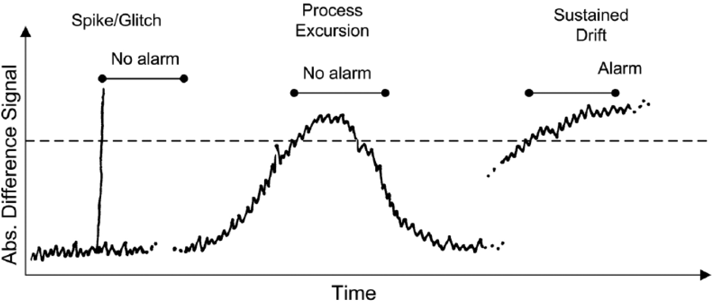
The delay time needs to be set sufficiently long to avoid spurious nuisance alarms due to transient discrepancies that will arise from healthy measurement systems. These may arise from noise effects or from differences in time response in the measurement systems. The delay should be several times longer than the period of any dominant noise component and longer than the expected duration of transient discrepancies due to a difference in measurement lag times (and certainly therefore longer than any difference in measurement dead time lags). Measurements selected for comparison will typically be of similar type and location such that there will not normally be a large difference in the responsiveness of the measurements. The size of any transient discrepancy would depend on the differences in the measurement time lags, and the process excursion rate and duration. The appropriate delay may perhaps be most readily identified empirically by observing the process behaviour (the time spent above the healthy steady state discrepancy threshold during plant excursions). Delay time is not critical provided it is long enough to suppress nuisance alarms. Although long delay times could be used to suppress nuisance alarms, the delay time should not be extended arbitrarily since this would delay the alarming of a genuine alarm condition and the prompt to investigate and rectify faults ( Figure 2 ). Delay times are typically expected to be of the order of minutes rather than hours.
Examples of signal trends
Potential nuisance alarms due to these transient discrepancies could also be suppressed by raising the alarm threshold, but this would also compromise the ability of the comparison to detect deterioration in the measurement systems and is not the preferred approach. Differences in measurement system scaling should be accommodated in the difference calculation, but for effective comparison, the measurement ranges should overlap for all operating regimes that may persist and where a demand might be placed on the protection. (Otherwise, operation could persist at a condition where the comparison is effectively disabled.) If there are anticipated operating circumstances where an out-of-range condition would generate a nuisance alarm, an automatic inhibit on detection of this circumstance may be configured – E.G. valve position or control set point. If these circumstances could persist AND could give rise to a real demand on the protection, then an inhibit of the alarm is not an acceptable approach; the measurement provisions should be revised to remove the out-of-range condition. Detection of the out-of-range condition itself should NOT be used to inhibit the alarm since the out-of-range condition could be due to a measurement failure rather than operating point changes. Trip points should be biased by the discrepancy threshold to allow for the possibility that a discrepancy of that magnitude could persist and not be alarmed. To reduce common mode potential, it would be preferable to route the measurement signals via different control system input modules.
II. PFD Contribution
A measurement comparison alarm is effectively a diagnostic provision that will detect some of the dangerous failures in the sensor subsystem of a trip function that would otherwise have been unrevealed. It will not, however, detect common mode failures that influence both measurement systems equally.
We can estimate the effective diagnostic coverage (DC) provided by a measured variable comparison (MVC) alarm as follows

where λDD is the dangerous detected failure rate and λD is the dangerous failure rate.
Given common mode factor β, the dangerous detected failure rate may be established from the NON common mode dangerous failure rate × the probability of a successful alarm response

where Pca is the PFD of the MVC alarm and the required operator response.
Giving

With Pca typically assigned a value of 0.1, we may identify the following representative values:
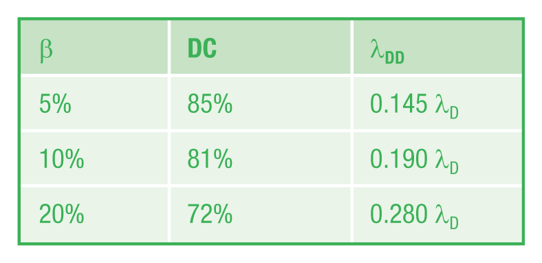
Substitution of these values in sensor subsystem PFD calculations will then allow proper determination of the system PFD with the nominated test intervals.
Note that we have identified here the DC due to the MVC provision which will include the process connections if these are included in the nomination of λD and β; it is suggested that this DC figure should be used in lieu of any figure identified for a trip transmitter/device alone. (It is to be expected that the comparison with an independent measurement will provide more coverage than possible from intelligent monitoring provisions in a single device.) If DC, Safe Failure Fraction (SFF) and total failure rate (λT) are declared for a device, λD for the device may be calculated as

This figure should be increased to account for process connection dangerous failures if appropriate. (See Dearden 1 for a discussion of such considerations.)
If required, given DCNEW, SFFNEW may be calculated as

If a device had an SFFOLD of 50% with no diagnostics (DCOLD = 0), then an MVC alarm with common mode factor of 10% would give an SFFNEW of 90%.
III. Conclusion
The approach outlined in this paper may offer a relatively straightforward tool with which to enhance a trip function, requiring only configuration of a DCS or equivalent. Some care is needed to ensure that the nuisance alarm rate is suitably low, so that the alarm remains credible and will prompt investigation and repair as appropriate, but that said, the tuning of the alarm is relatively straightforward and robust. Claims made for the alarm will be constrained by the reliability of the operator response and the nature of the system in which the alarm is configured.
Assuming a common mode factor of 10%, and a typical total system PFD contribution from a sensor subsystem of 30%–50%, we can anticipate overall system PFD will reduce to approximately 75%–60% of its value without a comparison alarm, assuming test intervals remain the same. Conversely, the deployment of a comparison alarm may allow an extension of function test intervals (by a factor 1.33′–1.66′) to a more practicable frequency. If the original test frequency for other subsystems was maintained, the sensor subsystem test interval could be increased by a factor of 5.
The gain is modest, but still potentially useful in some circumstances. The alarm will also help identify degradation that might otherwise lead to a spurious trip.
Footnotes
Funding
This research received no specific grant from any funding agency in the public, commercial or not-for-profit sectors.