
Abstract
Aiming at the problems in parameter measuring of small-size workpieces, a real-time detection system is developed based on machine vision. The system’s hardware composition and software design proposal are introduced, and the method of using digital image processing technology to measure geometrical size is elaborated. First, the image is acquired through industrial camera in the system. Then, the image is sent to the processing unit for processing, including the image filtration, template matching and image edge detection. Finally, the geometrical sizes are measured based on the calibration information of the system. The experiment shows that the system has a measurement error of less than ±0.05 mm and has the advantages of non-contact, rapid speed, high precision and strong anti-interference capability, which provides a new approach for the online non-defective detection of the workpieces.
I. Introduction
In the mass production of workpieces, in order to guarantee the product quality, it is required to measure the side length and circle diameter of the semi-finished or finished workpieces on site. The traditional method is to use electronic calliper, bore gauge or measure gauge for measuring, which is time-consuming, and will cause mental and physical exhaustion; besides, it is very easy to cause measurement error due to the small size and irregular shape of some workpieces. 1 This will increase huge labour cost and management cost to the factories while not ensuring the ‘zero defect’ of products. The development of modern manufacturing industry proposes higher requirements for the size measuring of workpieces. Therefore, researching and designing a system to measure the workpiece parameters rapidly in practical production have become the demand of the whole society.
In recent years, with the development of computer, digital signal processing and artificial intelligence technology, computer vision technology has become one of the effective methods to monitor the product quality and diagnose product faults as a brand new non-defective detection means gradually, which presents a powerful vitality in the workpiece measuring technology.2,3 The machine vision technology is to obtain the image of measured target through image sensor and then send it to the image processor for judgment and measuring of target size and shape according to the information such as pixel distribution and brightness. Compared with the traditional detection means, it has the advantages of non-contact, rapid speed and high precision and can greatly reduce the labour intensity of the detection personnel, with quite an important theoretical significance and application value.4–8
Based on the actual workpiece, a design proposal of gear parameter automatic analysis system is proposed in this paper, the acquired workpiece image is input to the computer and the characteristics are extracted and sizes measured according to image processing algorithm, with a good effect in the production application.
II. Composition of Measuring System
The hardware of the measuring system mainly consists of workbench and its holder, industrial camera, lens, backlight source, motor controller, computer and output equipment. The overall structure of the system is shown in Figure 1 . Its working process is that the workpiece to be measured is transmitted to the rotary glass table after sequencing through the vibration disk, and the backlight source is placed under the platform, so that each workpiece can be lighted uniformly. The industrial camera is equipped with lens above the workpiece, which can acquire the workpiece image for the computer; the computer processes, locates and measures the image to obtain the number of pixels of the workpieces and convert it to the actual size. The system compares the measured value with the set value and directly drives the external equipment through I/O card to realize the alarming and sorting.
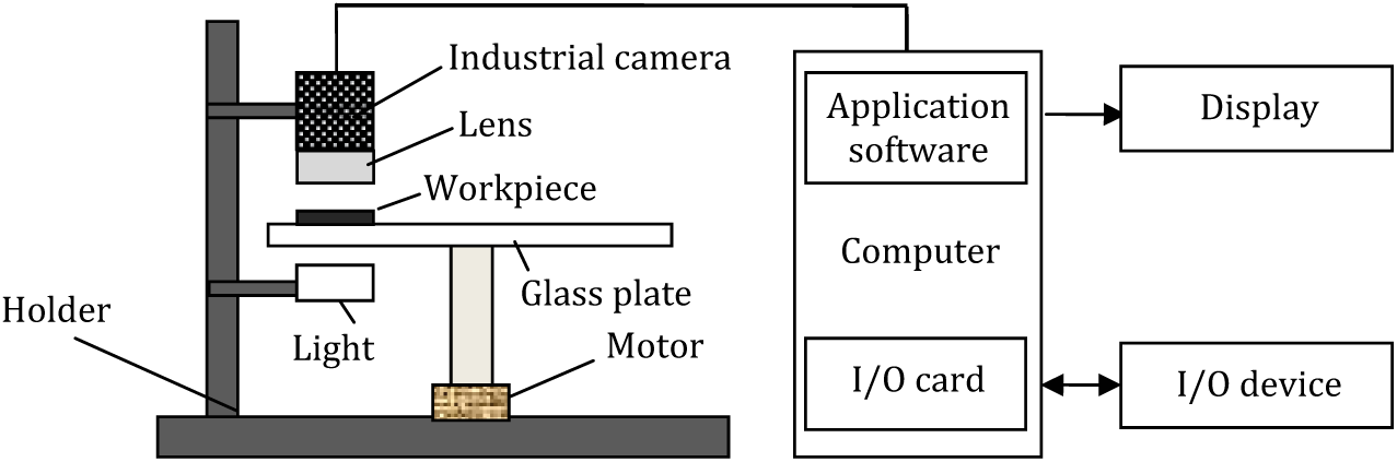
The whole structure of measuring system
The software is installed in the computer with the operating system Windows XP. The development of the application program is based on the idea of modular design, including image processing program and operation control program. The image processing mainly includes the image acquisition, system calibration, grey level transformation, image filtration, image matching, edge extraction, parameter analysis and statistics, result information display and data saving; the movement control includes material loading control, product sorting and alarm setting. The module structure of the software is as shown in Figure 2 .
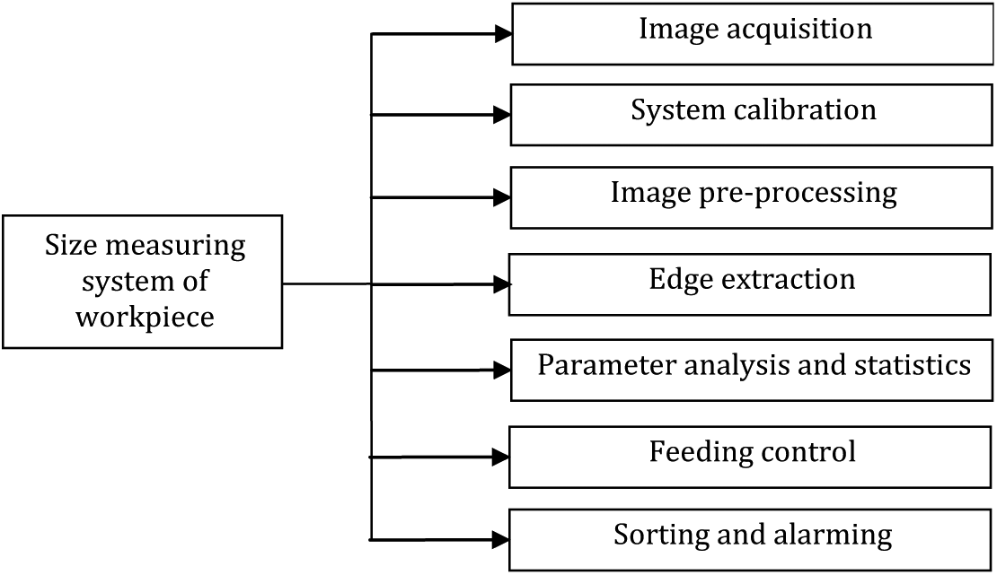
Parameters measuring module of workpiece
The main task of this measuring system is to complete the real-time measuring of length, width, bore diameter, deviation angle of the rectangular workpiece and their geometrical central coordinates.
III. Image Processing Method of System
Image is the information transfer carrier of machine vision measuring system, and the quality of its original information obtained and advantage of image processing algorithm will directly influence the system performance. Therefore, in order to realize high-precision automatic measuring to the workpiece parameter, it is required to complete the operations such as image acquisition, system calibration, image preprocessing, characteristic positioning and size measuring. The specific flowchart is as shown in Figure 3 .
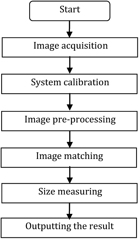
The flowchart of image processing in system
A. Image acquisition
In the detection platform, two million pixels industrial camera with USB interface is adopted to acquire images. The image sensor within the camera can convert the light of different wavelengths reflected by the target into an understandable two-dimensional matrix. The reasons of adopting USB camera are as follows: (1) the price of USB digital camera is appropriate, and its performance can basically meet the demands of measuring accuracy; (2) the USB digital camera has a relatively simple hardware system structure, and it can communicate with the computer directly without allocating an image acquisition card additionally. When acquiring the image, the target is below the industrial camera, the backlight source is turned on and it can be guaranteed that the target is completely imaged in the visual field. The acquisition method selected is external triggering, that is, after image measuring, the computer will send out a command to control the re-exposure of camera and to acquire the next image through the I/O card.
B. System calibration
The image acquired by the system records the structural and size relationship between objects, with pixel as the basic unit. Therefore, the corresponding relationship between each pixel and the size of real object it represents must be established, and this requires calibration. The camera imaging model is shown in Figure 4 , where PQ is the object, P′Q′ is the image, u is the object distance, v is the image distance and f is the focal distance. When the system parameter is invariant, the ratio of P′Q′ will also remain unchanged. Measuring the size of P′Q′ can reflect the size of PQ directly. In this system, the calibration method adopted is to place the target workpiece right below the lens and obtain the distance in an image by calculating the known target size. That is to say, in the known standard workpiece, the distance between P and Q is L, and the number of pixels between P and Q in the image is M, so it can be known that k = L/M, in which k is the pixel equivalence, representing the k unit length of workpiece in each pixel. Therefore, when the number of pixel points in the image is obtained, the real distance of any two points in the image can be obtained from k accordingly. For example, it is known that the number of pixels in the image is M = 1000, and the real length of workpiece is L = 50 mm, then the size represented by each pixel is k = L/M (in mm/pixel).
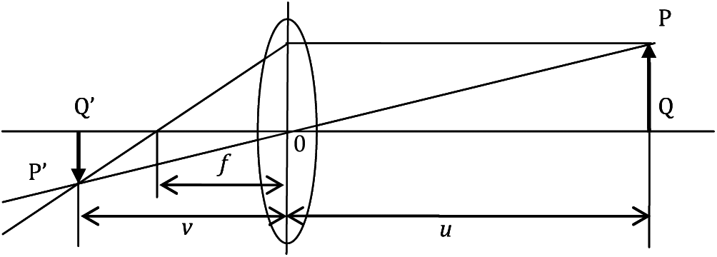
The imaging model of camera
C. Image preprocessing
In the process of image acquisition, the external ambient lighting or machine vision system itself will cause random noises, which will influence the image quality directly. In order to eliminate the noise brought by the image, median filtering method is adopted to filter some noise points. The median filtering is a nonlinear filtration method, the advantage of which is to keep good contour information and eliminate the noise. Assume that g(x, y) is the grey value of point (x,y) in the original image, the region of N × N (N = 3 or 5) is the filter window and G(x,y) represents the grey value of the filtered image at (x, y), then the output of middle value filtration can be expressed as

where Med{ } represents the middle value of all pixels in the window. After median filtering, the random noise in the image is eliminated effectively.
D. Image matching
In order to meet the requirements of flexibility of the workpiece in the online measurement, there is no need to reload and position the workpiece in this system. This system adopts the shape-based matching method for automatic locating. By using this method, the image processing algorithm can automatically locate any positions in the detection area, and finally calculate the size according to the setting. In the first step, the matching position of the workpiece is subjected to average processing according to the 2 × 2 adjacent area to obtain an image with relatively low resolution, then to obtain an image with an even lower resolution with the same method and finally to get an image pyramid. The second step is a matching process from rough to fine. The matching is conducted on the layer with a lower resolution first; if the measured value of the similar line is less than the set threshold T, then image of a higher resolution will be matched, meanwhile, abandoning those pixels larger than the threshold until the n-level image of the original resolution. As shown in Figure 5 , Figure 5(a) is the template image and Figure 5(b) is the real acquired image. The image matching can automatically determine the position of the measured size.
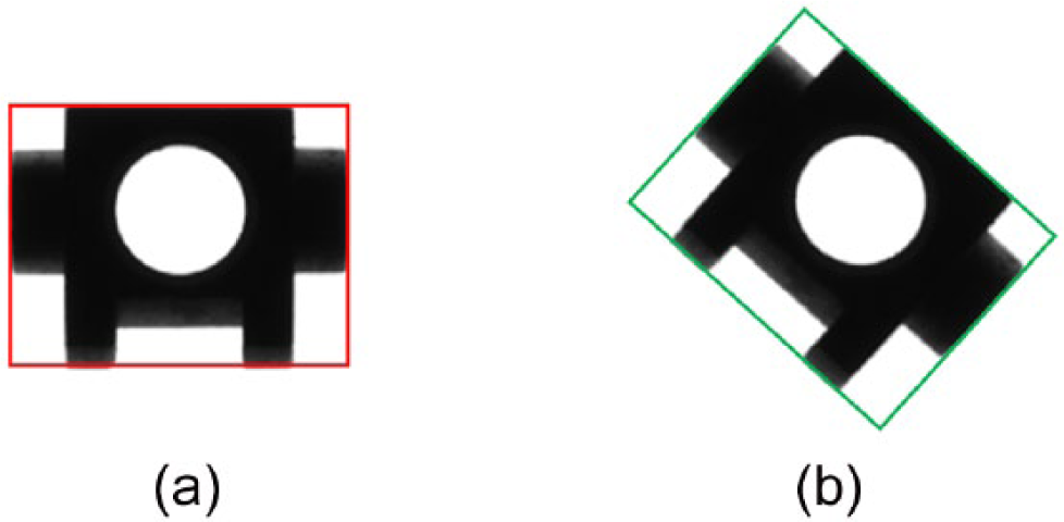
Image matching: (a) template image and (b) image to be matched
E. Edge extraction
In the image-based measuring system, the edge detection of object is the key of the whole measuring, which plays a decisive role for the precision of the measuring result. For the digital image, the edge information of the object is contained in the variation of the image grey value, meaning the ending of one region and the starting of another, and it generally exists between the object and background, object and object. According to edge grey mutation of the target, we can use the gradient value of pixel point to distinguish the edge point and non-edge point and obtain the edge position by comparing the gradient of each pixel point. It is needed to use Sobel operator for edge extraction operation, and the description of this method is as follows

The traditional edge detection operator can only extract the pixel-level edge. In case that under the condition of one dimension, the object with length of 5.5 pixels might be quantified into 6 pixels in the process of quantization, the detected result is 0.5 pixel more than the actual length, and the error of 0.5 pixel causes inaccurate measuring result; the principle is as shown in Figure 6 . In order to improve the precision, on the basis of obtaining the pixel-level edge, the surrounding grey information is used to subdivide the pixel point, that is, to extract the sub-pixel-level edge. After the sub-pixel-level edge point is obtained, the sub-pixel edge of the workpiece can be fitted, so that the edge can be positioned in a more accurate position.
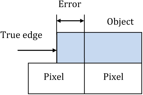
The schematic of sub-pixel
F. Parameter measuring
Parameter measuring is the process to calculate the pixels number of edge extracted in image and then convert it to the geometrical size of workpiece through the calibration value. As shown in Figure 7(a) , after processing with the above image processing algorithm, the computer obtains the coordinate set of the object which is connected to the pixel width edge contour, and these contour points form some basic primitives, such as point, line, circle and arc, and the edge contour of the object is composed of these basic primitives. In the size measuring system, it needs to identify the position of some designated primitives, or the coordinate value of the designated points, so as to calculate the number of pixel between two sub-pixel edges, and thus to calculate some important parameters. The workpiece size measured by this system is the size length and inner diameter of circular hole, and its position image is as shown in the red line in Figure 7(b) .
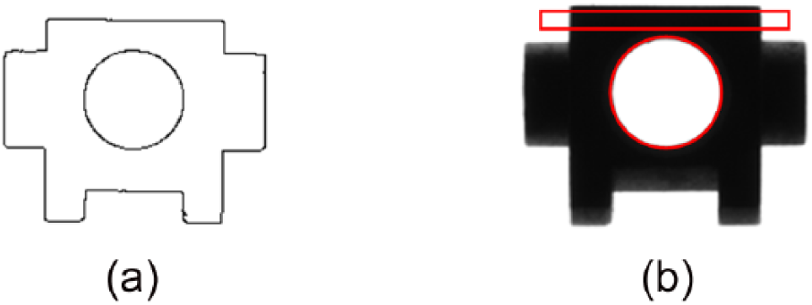
The principle of parameter measuring: (a) The contour of workpiece and (b) position to be measured
IV. Experiment and Result Analysis
In order to verify the performance of the detection system, we select a higher precision instrument to measure a standard workpiece of size 5.502 mm. The experiment is repeated for 10 times, and the analysis is mainly made from the measuring accuracy and speed. The detection result of size L and its analysis are shown in Table 1 .
The measuring result and its analysis.
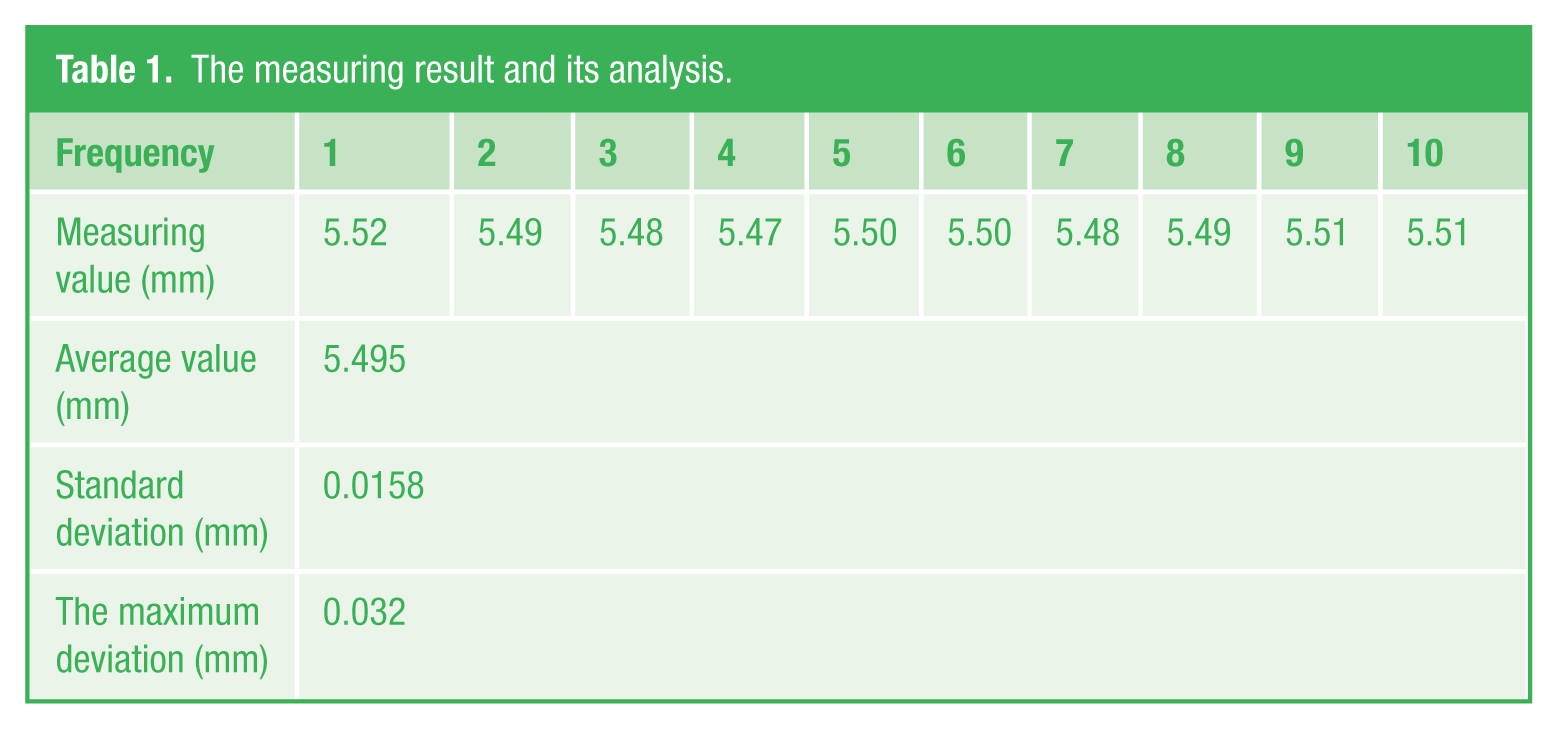
It can be seen from the analysis result that the difference of the average value between this system and the other higher precision instrument is less than 100 µm level, which indicates that the detection precision of the workpiece size machine detection system can be up to 10 µm. The standard deviation and maximum deviation of the measuring are relatively little, which indicates that the measuring system has a good repeatability and high stability.
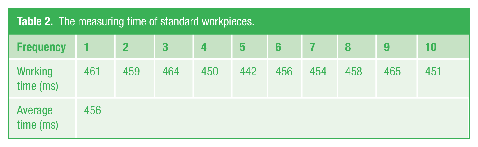
The detection time (not including the linear scanning time of precise standard part) is as shown in Table 2 , and the average detection time of the precise standard workpiece is 456 ms, which can meet the requirements of real-time online detection.
The measuring time of standard workpieces.
Theoretically, the precision of the machine-vision-based measuring system mainly depends on the camera resolution, that is to say, the higher the resolution of camera equipment, the smaller the actual size represented by a pixel in measuring and the higher the measuring accuracy will be. But in the process of measuring, the differences of equipment, environment and methods will cause error. The common error factors include the following:
Calibration error. It means the error exists between the conversion of pixel value and the actual size value in the process of calibration.
Hardware system error. The error of image edge extraction caused by the shadow of workpiece thickness or uneven lighting, unparallel measurement error between the camera imaging plane and the object plane and the nonlinear image distortion error due to lens distortion when the optical signal is converted into electrical signal.
Software algorithm error. In the measuring algorithm, the circular centre of the workpiece is obtained from the least square method fitting by extracting the edge points, and there exists certain error in this kind of algorithm.
Therefore, in order to reduce the influence of error, the system adopts the method of average calculation in more value taking.
V. Conclusion
In this paper, a machine-vision-based workpiece parameter measuring system is designed. The running experiment shows that the system hardware has a simple structure with stable and reliable work, which can greatly improve the production efficiency and production automation degree, with a greater theoretical and practical value. Compared with the artificial sampling inspection, the machine vision automatic measuring system has the following advantages. First, the detection comprehension is improved: the traditional method is sampling inspection according to the proportion of 1/3, while the machine vision equipment can conduct full inspection; second, the detection result consistency is improved: the artificial detection is easy to be disturbed by the workers’ eyesight and emotion and so on, and the detection result of the same workpiece might vary from different persons, while the machine vision system can realize the objective and stable detection result; third, the detection efficiency is improved, and the system detection speed can be up to 120 devices/min, equivalent to the work amount of 20 persons. Fourth, the detection cost is saved and economic benefit increased. Compared with artificial detection, if this equipment is used, only one worker is required to operate the equipment, which greatly reduces the labour and management cost, and in the long run, it increases considerable economic benefit to the manufacturer. This system has been adopted by mechanical part manufacturing enterprises, with a good economic benefit.
Footnotes
Funding
This work has been supported by Shandong Provincial Natural Science Foundation, China (No. ZR2013FQ036), the Spark Program of China (No. 2013XH06034), the Spark Program of Shandong Province (No. 2013XH06034) and Technology Development Plan of Weifang City (No. 201301015).