
Abstract
This paper discusses a diagnostic method of monitoring the integrity of dip-pipe legs applied in back-pressure level and density measurement. Applications are often vulnerable to two common faults in instrument pipework: leaks and blockages. Both are surprisingly difficult to diagnose on plant, so a new diagnostic technique has been jointly developed for use at Sellafield site.
I. Introduction
In level and density measurement, the hydrostatic pressure on the ends of dip-pipes is measured (see Figure 1 ).
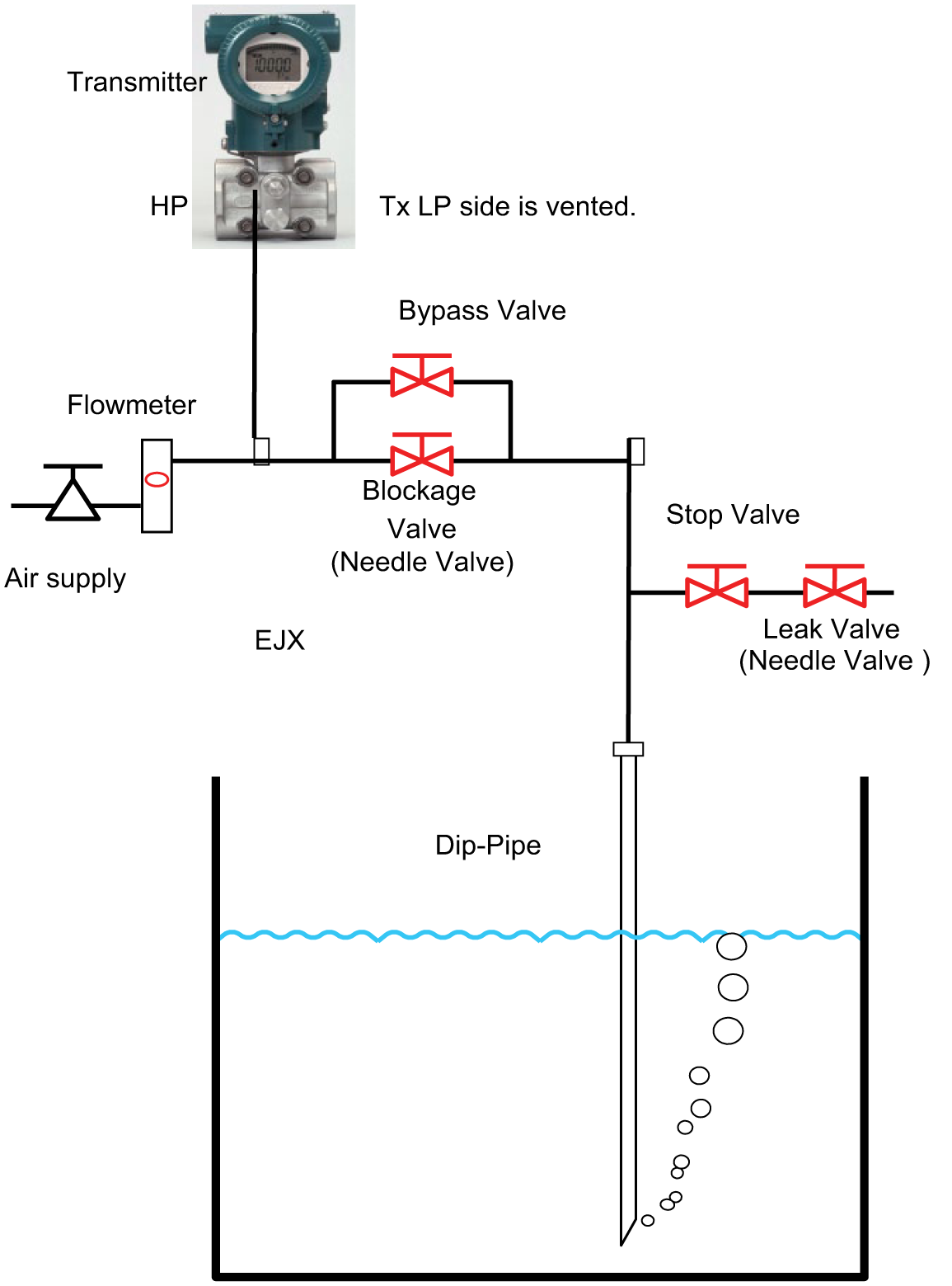
DP measurement principle for level and density
The Achilles’ heel for level and density differential pressure (DP) measurements is their vulnerability to blockages and leaks in both the high-pressure (HP) and low-pressure (LP) sides of the instrument pipework This vulnerability is often impossible to design-out because there is no choice but to use long pipes to reduce the process fluid temperature, or the fluid under measurement is hazardous, contaminated or has a tendency to solidify. Dip-pipes cannot be pressure tested as they are open-ended.
Today, nearly all modern process instruments contain a powerful microprocessor; however, it is only recently these have become powerful enough to undertake the task of real-time statistical diagnostics. Instruments typically pass such diagnostic status data through a simple digital network called HART®.
All process plant equipment generates ‘noise’. This noise is generated by physical plant operations (e.g. pumps, filters, control-valves) and is conducted in pipes, vessels, mechanical structures and process fluids. Traditionally, this noise was regarded as degrading the transmitted signal and was often removed by damping or filtering. Now, this noise can be used to gain an insight into the health of a DP measurement to assess whether the dip-pipes are blocking, leaking or generally becoming unreliable.
II. DP Measurement Principle for Level and Density
The hydrostatic pressure within a vessel is measured by the insertion of a dip-pipe into the liquid ( Figure 1 ). By passing a small flow of compressed air into the dip-pipe, the liquid column in the dip-pipe is pushed out and air bubbles are formed in the liquid. The rate of air flow must be small enough to have minimal effect due to pressure drop along the pipe length, but sufficient to bubble through the liquid. The back pressure of the air in the dip-pipe is now equal to the hydrostatic pressure of the liquid column and can be measured with a DP transmitter.
A. Advantages
Instruments do not come into contact with the liquid.
Instruments may be located outside the hazardous area and not contaminated by the process liquid.
Simple to engineer and straightforward to commission and test.
Cost-effective.
Well-proven and understood technique.
Vessel can contain complex internals (stirrers, cooling coils, etc.) without affecting the level or density measurement.
B. Disadvantages
Potential for dip-pipe blocking due to drying or crystallisation at the dip-pipe tip.
Measurement is sensitive to pipework leaks.
If air supply is lost, measurements become meaningless and may not be fail-safe.
Air (or gas) must be compatible with the process. Never aerate flammable liquids. Some liquids can cause blockages of dip-pipes, for example, due to the presence of natural CO2 in air. In these cases, inert gas or ‘CO2 lean-air’ must be used instead of ambient air.
III. The Nature of the Problem
The challenge was set by Sellafield Ltd in late 2010 to determine whether the existing statistical process monitoring used by the Yokogawa® Impulse Line Blockage Detection (ILBD) advanced diagnostic in their EJX DP transmitter could also be used for dip-pipe level measurements. In particular, Sellafield wanted to know the following:
Could the ILBD statistical monitoring detect a blockage in the dip-pipe?
Could ILBD also be used to detect a leak in the instrument pipework?
Could ILBD detect the loss of purge air?
All this was uncertain since the noise generated by dip-pipe level measurement would be small, possibly at the threshold of detection by both the EJX sensor and the ILBD firmware; therefore, a practical experiment was devised to determine the feasibility of an adapted ILBD diagnostic.
IV. Experiment in Adapting the Existing ILBD Diagnostic
The Yokogawa EJX DP series of pressure transmitters measure two parameters:
The static pressure (SP) of the LP side of the transmitter;
The DP between the HP and LP sides of the DP transmitter.
By monitoring these parameters at a very high data rate, the ILBD is able to calculate two further parameters:
DP fluctuation (fDP), essentially the signal-to-noise ratio of the DP measurement;
SP fluctuation (fSPh and fSPl), essentially the signal-to-noise ratio of the SPs in both the HP and LP sides of the transmitter.
In dip-pipe back-pressure applications, the connecting pipe and dip-pipe length and internal diameters are fixed, and liquid levels generally change slowly relative to measurement data sampling rates. It follows that significant change in the regular measurement fluctuations due to ‘bubbling’ may be due to either pipe leakage or dip-pipe blockage.
To demonstrate that the transmitter ILBD capability could be applied to dip-pipe level and density measurements, Yokogawa conducted an experiment at their factory ( Figure 1 ). A flow control valve was used to set the air flow to 15 L/h at standard temperature and pressure (STP). Adjusting needle valves were used to simulate blockage and leakage conditions.
During the setup of the experiment, a couple of issues were discovered with the metering valves, in that they would not fully open or fully close; therefore, two ball valves were added to supplement the needle valves – one was placed in a bypass position, while the other was used as a shut-off valve.
The water level was varied to determine whether this would have an impact on the ILBD diagnostic and to further determine what the minimum level might be for reliable detection of either a blockage or leakage in the dip-pipe.
A. Experimental Conclusion
The existing ILBD in the pressure transmitter is of detecting both leakage and blockage in connected dip-pipes as follows:
DP fluctuation (fDP)
SP fluctuation (fSPh and fSPl)
Blockage factor (BlkF)
Blockage factor (BlkF) cannot be applied because of the lack of fluctuation of SP on the LP side of the EJX. However, this is irrelevant to dip-pipe applications.
Lower limit of DP process variable in the application of ILBD
Default value is 0.05 (5 kPa). This value was changed to the lower value for dip-pipes, approximately 0.02 kPa (
Figure 5
).
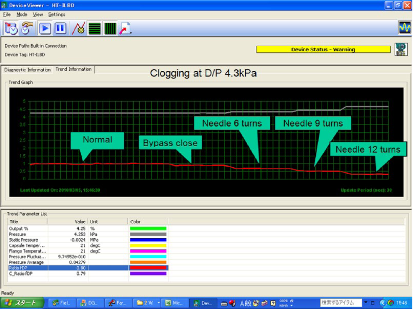
Simulated dip-pipe blockage (at 43 cm water level)
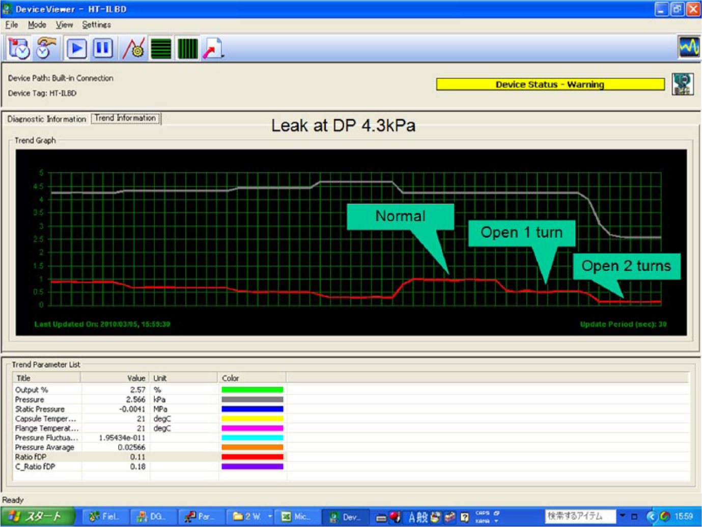
Simulated dip-pipe leak (at 43 cm water level)
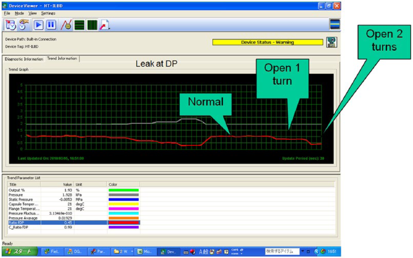
Simulated dip-pipe leak (at 19 cm water level)
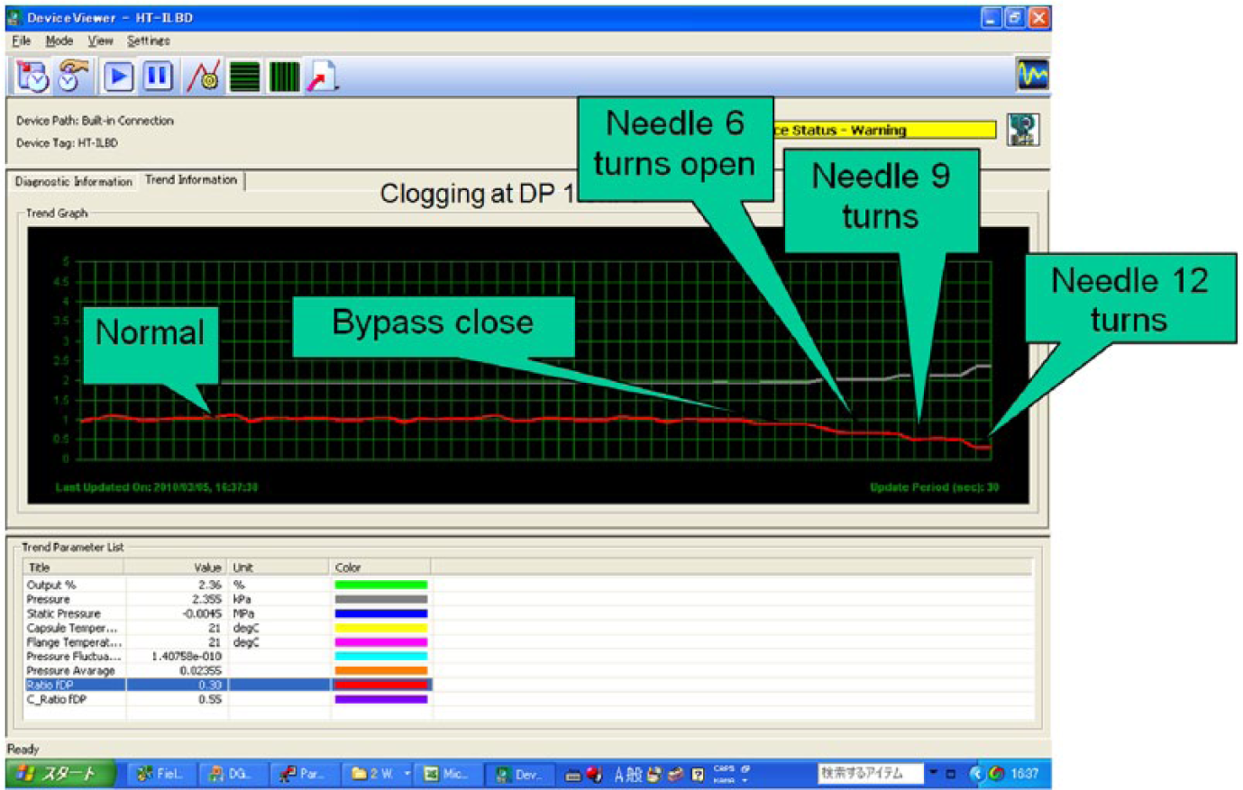
Simulated dip-pipe blockage (at 19 cm water level)
V. Implementation at Sellafield Site
The actual application would deviate from the experiment in two important respects:
The amplitude of background process noise will be different (probably more).
The application utilised an air flow controller instead of a simple metering valve. This maintains a constant 15 L/h STP output, irrespective of the tank level.
A particularly problematic application was chosen within Sellafield’s Solvent Treatment Plant. Here, liquid caustic level and density are measured using dip-pipes. Installations are prone to regular blockages and occasional leaks. These require frequent, routine and costly maintenance, yet still produce unwanted plant breakdowns.
An existing level transmitter was replaced 1 with a Yokogawa EJX type, complete with ILBD diagnostics. The measurement signal was trended on the plant SCADA system. The historical level measurement problems inherent in the plant installation were confirmed prior to the test work.
The transmitted HART signal was analysed and a ‘healthy’ value for the DP fluctuations established. 2 A first estimate was made for alarm values for both blockage and leakage, and these were set (HART status 86 flag, Figure 6 ). Over a period of several months, these values were adjusted as our knowledge of the process increased.
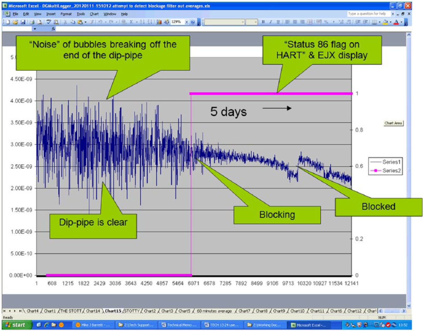
Actual data from the Sellafield application
VI. Results from Over 1-Year Use at Sellafield
The modified ILBD diagnostic has been in use for over a year at Sellafield now. The results are excellent. Highlights include the following:
The detection of a leak from a faulty pipe coupling incorrectly tightened after maintenance;
Several detections of blocking dip-pipes, often giving a 5-day advanced warning to our maintenance staff, allowing timely, routine intervention and avoiding plant outages;
Considerable interest from other Sellafield plants in its use in similar applications;
The specification of this ILBD in all future new-build plants and applications at Sellafield.
VII. Glossary of Terms
EJX®: Yokogawa® model number of their DP transmitter.
HART: Highway Addressable Remote Transmitter protocol.
SCADA: Supervisory Control and Data Acquisition system.
Footnotes
Acknowledgements
We thank Mark Halliwell at Yokogawa, UK, and Gavin Morgan at Sellafield for their work on the first implementation. We acknowledge permissions from Yokogawa and Sellafield Ltd to publish this work.
Conflict of interest
All registered products/trademarks, brand names and logos are the property of their respective owners.
Funding
This research received no specific grant from any funding agency in the public, commercial or not-for-profit sectors.