



Abstract

I. Introduction
Accurate and repeatable temperature measurement requires that the Instrument Design Engineer understands the various methods available, their performance and limitations. This paper addresses the basics of temperature measurement as commonly applied in the process industries. The properties and application of resistance temperature detectors (RTDs), thermocouples, thermistors, dial thermometers, temperature transmitters and switches are discussed. Temperature is also measured by infra-red pyrometers which have the advantage of being non-invasive and by other methods, details of which may be found in the referenced publication. 1
II. Temperature Scales and Units
Temperature is measured using various temperature scales primarily Celsius (°C), Fahrenheit (°F), Kelvin (K) and Rankine (°R). The lowest possible temperature, known as absolute zero, is −273.15 °C, and the Kelvin scale was chosen so that its zero is at this point with a Kelvin being the same as a degree Celsius, giving

Using the Rankine scale, absolute zero is −459.67°F, giving

It is important to note that the gas laws, used in gas flow metering are based on using the absolute scales of temperature (T) and pressure (P). The general gas law describes the relationship between these values and the resulting effect on the gas volume (V) should either of them changes (States 1 and 2)

And for a gas of molar mass (MW – kg/kmole) with flowing conditions of temperature tF (°C) and pF (barg), the gas density (ρF) is determined from

This relationship is based on the fact that 1 kg mole of gas occupies 22.415 m3.
The International System of Units (SI) uses the Kelvin (K) as the basic unit of temperature. For most applications, it is more convenient to use the Celsius scale in which 0 °C corresponds to the melting point of ice and 100 °C at 760 mm Hg to the boiling point of water.
In the United States, the Fahrenheit scale is universally used. On this scale, the freezing point of water corresponds to 32°F and the boiling point to 212°F ( Table 1 ).
Temperature unit conversion

For calibration purposes, fixed-point temperatures are used which are based on physical phenomena that are easily observed and consistent in nature. For example, water at its triple point (TP) 273.15 k or 0.01 °C where the TP is the equilibrium temperature at which the solid, liquid and vapour coexist; other examples include mercury at TP 38.8344 °C and tin at freezing point 231.928 °C.
III. RTDs
RTD elements are normally constructed of platinum (Pt), copper or nickel, with Pt being the preferred material in the process industries. This material has a predictable and reproducible change in resistance with temperature. Typically, the change in resistance with temperature is made use of by having the RTD in one arm of a direct current (DC) Wheatstone bridge to obtain a DC voltage output proportional to the change in temperature. RTDs are tending to replace thermocouples below 600 °C avoiding the installation constraints associated with compensating cables.
RTDs provide good accuracy, excellent stability and repeatability. Platinum RTDs are very stable and are not affected by corrosion or oxidation. RTD measurement circuits are relatively immune to electrical noise especially around motors, generators and other high-voltage equipment. Each type of temperature sensor has a particular set of conditions for which it is best suited. RTDs offer a wide temperature range with −50 °C to 500 °C for thin-film sensors and −200 to 850 °C for wire-wound sensors and thus can be used in all but the highest temperature industrial processes.
The DIN 60751 (formally DIN 43760) or IEC 751:1983 Pt100 Standards are used worldwide for platinum RTDs. The standards require the RTD to have an electrical resistance of 100.00 Ω at 0 °C and a temperature coefficient of resistance of 0.00385 Ω/°C between 0 and 100 °C.
RTDs are most commonly manufactured in three- and four-wire configurations with single- or duplex-element arrangements ( Figure 1 ). The three-wire configuration is most commonly used.

RTD wiring diagrams
A. Three-Wire RTD Measuring Circuit
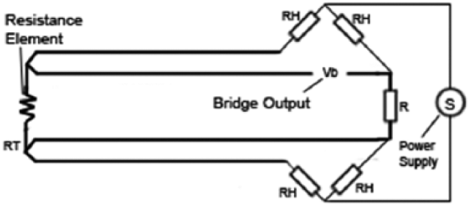
In order to minimise the effects of the cable resistances, a three-wire connection ( Figure 2 ) arrangement can be used. Here, the two wires to the sensor are on adjoining arms. There is a lead resistance in each arm of the bridge so that the resistance is cancelled out, so long as the two lead resistances are equal. This arrangement allows up to 600 m of cable.

Three-wire RTD measuring circuit
B. Four-Wire RTD Measuring Circuit
The four-wire resistance thermometer configuration increases the accuracy and reliability of the resistance being measured: the resistance error due to lead wire resistance is zero. In Figure 3 , a standard two-terminal RTD is used with another pair of wires to form an additional loop that cancels out the cable resistance. The above Wheatstone bridge method uses a little more copper wire and is not a perfect solution. Figure 4 shows a better arrangement, four-wire Kelvin connection. It provides full cancellation of spurious effects; cable resistance of up to 15 Ω can be handled.

Four-wire RTD measuring circuit
Four-wire RTD measuring circuit
C. Four-Wire RTD Measuring Circuit
Platinum RTD tolerance compliance accuracies are shown ( Figure 4 and Table 2 ). RTD calibration tables can be downloaded from http://www.te-direct.com.
Platinum accuracy Classes A and B to ASTM E1137 and DIN EN 60751

IV. Thermocouples
A thermocouple is manufactured by fusing or welding together at one end two wires of dissimilar metals to form a ‘hot’ or ‘measuring’ junction with the free ends available to the ‘cold’ or ‘reference’ junction. Heating one end induces a current flow in the thermoelectric circuit ( Figure 5 ) that depends on the metal pairing and is known as the Seebeck effect

where α is the Seebeck coefficient, the constant of proportionality (µV/°C); Tj1 is the hot junction temperature (°C) and Tj2 is the cold junction temperature (°C).
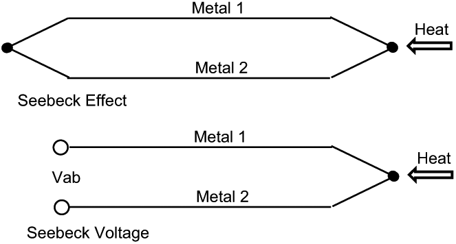
Thermoelectric circuit
For example, if α = 40 µV/°C, Tj1 = 80 °C and Tj2 = 40 °C, this produces Vab = 1.6 mV. Thermoelectric behaviour is governed by the following laws.
A. Law of Homogeneous Materials
A thermocouple circuit made using a homogeneous wire cannot generate an electromotive force (emf), even if it is at different temperatures and thicknesses. Consequently, a thermocouple must be made from at least two different materials to generate a voltage.
B. Law of Intermediate Materials
The sum of all the emfs in a thermocouple circuit using two or more different metals is zero if the circuit is at the same temperature, see Figure 6 .

Law of intermediate metals
Consequently, the addition of different metals to a circuit will not affect the voltage created. The added junctions must, in this event, be at the same temperature as all ‘cold’ junctions in the circuit, allowing a third metal such as copper leads to be added when connecting measuring instruments.
C. Law of Intermediate Temperatures
The sum of the emfs generated by two interconnected thermocouples, one with its junctions at 0 °C and some reference temperature and the other with its junctions at the same reference temperature, is equal to that of a single thermocouple with its junction at 0 °C.
In practice, this also allows extra wires with the same thermoelectric characteristics to be added to the circuit without affecting its total emf. It also permits cold junction compensation to be carried out by receiving instruments.
D. Thermocouple Types
There are several types of thermocouple, each designated by a single letter, with different material pairings in common use, which is suitable for specific temperature ranges and to meet certain accuracy requirements; see Table 3 .
Thermocouple application ranges and tolerances

Use the greater value between °C and %.
The Type K chromel/alumel thermocouple is the most common due to its wide temperature range of 0–1260 °C. Types R and S platinum/rhodium are used for higher temperatures in the range 870–1480 °C. The protective sheath material that is used limits the application temperature, with refractory or Inconel sheaths being used at temperatures >1000°C.
For accurate and reproducible low-temperature measurement, the RTD is often preferred to the Type J iron/constantan thermocouple.
E. Thermocouple Circuit Calibration
For each thermocouple type, the DC mV output over its operating temperature range is detailed in calibration tables referenced to either 0 °C or 32°F. These tables can be downloaded from http://www.temperatures.com/tctables.html.
F. Compensating Cables
To reduce installation costs, thermocouples may be connected to remote instrumentation using compensating cable which has the same thermoelectric properties. The compensating cable is colour coded in accordance with the appropriate standard. The most common thermocouple types, application ranges and compensating cable colour codes are shown in Table 4 . Compensating cables should be screened and routed so as to avoid close proximity to power cables and should cross any such cables at 90° to avoid noise pickup.
Compensating cable standards

IEC: International Electrotechnical Commission.
G. Thermocouple Circuits
The diagram, Figure 7 , shows a Type J thermocouple connected to a voltmeter to measure the output of the thermocouple hot junction J1, but note that we have created two more junctions J2 and J3. Since J3 is a copper-to-copper junction, there is no voltage created; however, J2 is a copper-to-constantan junction which will add a voltage Vcj in opposition to Vh. To determine the temperature of J2, we can physically put the junction into an ice bath to force the temperature to 0 °C and establish J2 as a reference junction. The voltmeter reading becomes

where Vh is the thermocouple emf, Vcj is the cold junction reference emf and Vo is the output to receiver.
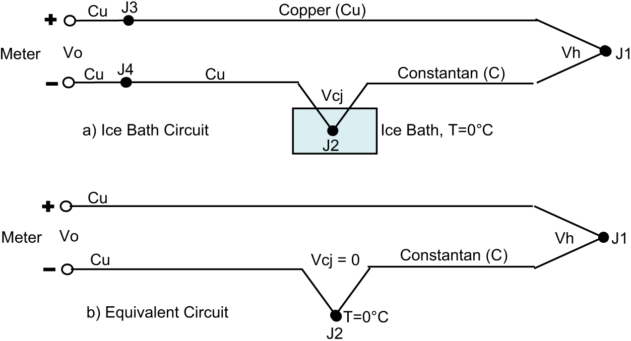
External reference junction
H. Cold Junction Boxes
These devices find application where a number of furnace thermocouples, typically of a mineral-insulated, stainless steel sheathed variety, can be gathered at a common location. Thermocouple calibration and cold junction compensation can be carried out by measuring the cold junction block temperature and applying circuit compensation within the box. This method permits signals to be cabled to remote receiving devices using standard copper multi-core cable. The diagram ( Figure 8 ) shows a Type K thermocouple configuration


Cold junction box
V. Thermistors
Thermistors are temperature-sensitive devices used when a higher output voltage than that provided by a thermocouple is required. Unsuitable for higher temperatures, they have a variety of uses including motor-winding temperature measurement and small-device electronic temperature control.
Thermistors are made from semi-conductor material having an inverse temperature coefficient, that is, their resistance decreases with increasing temperature. The change in resistance with temperature is not linear, which requires that the signal be linearised if used over a wide temperature span. This is particularly important where the measurement is used within a feedback loop.
VI. Temperature Transmitters
RTD and thermocouple loops require care when cabling to remote instrumentation. Screened cables are advised to minimise the pickup of ‘noise’. If there is a high number of measuring elements within a processing area, the individual element cables can be marshalled at junction boxes and then connected to the remote apparatus by multi-core cable. Transmitters for temperature elements may require being located remotely if they may be subjected to a high temperature.
RTD and thermocouples can have integral two-wire 4–20 mA transmitters mounted on the element connecting head. This allows the signals to be combined in cables common to other 4–20 mA transmitter signals. This signal strength has greater immunity to high inductive voltages and standardisation of the multi-core cabling and routings will save costs. Transmitters suitable for use in hazardous area and also transmitters employing radio transmission are available.
VII. Self-Powered Temperature Instruments
There are many situations that require local temperature monitoring where electrical or pneumatic power is not available or would be too expensive to provide ( Figure 9 ). There are several devices that can be used to satisfy this requirement. The reliability and accuracy of some of these local devices require high maintenance, and an alternative is to provide test thermowells at suitable locations for process investigations using calibrated devices when required.

Dial thermometers
A. Bimetallic Thermometers
A bimetallic strip curves or twists when exposed to a temperature change due to the different thermal expansion coefficients of the metals used. Linear expansion is defined by

where LT is the length at temperature T (m), LO is the length at starting temperature (m), α is the coefficient of linear expansion (dimensionless) and ΔT is the change in temperature (K)
Typically, a spiral wound element is used which provides a larger element in a smaller space. It is a low-cost instrument which has a relatively low accuracy and is affected by vibration, which is frequently experienced on pump and compressor installations. When infrequent but accurate measurements are required, it may be advisable to provide test thermowells.
B. Filled-System Thermometers
A filled thermal system is basically a pressure gauge element, such as a Bourdon tube, connected by capillary tubing to a bulb acting as the temperature sensor and as such is self-powered. The measurement principle is based on the following relationship between States 1 and 2, using absolute values of temperature and pressure

They are classified into four major classes according to the fill material, which can be liquid, vapour–liquid or gas, and sub-classes based on the ambient temperature compensation method used. Compensation can only be ‘instrument case’, using a bimetallic strip, or ‘full’ which uses an auxiliary capillary without the bulb, in parallel to the main capillary for greater accuracy.
Table 5 summarises the main properties but should not be considered as fully comprehensive. Reference should be made to other sources for detailed application considerations.
Filled temperature systems designations and main characteristics

The fill fluid must be compatible with the process fluid which may prevent the use of this technique in the food and pharmaceutical industries. They are not suitable for high-temperature measurement and can easily be misapplied if the user is not familiar with the characteristics of each system. They provide greater accuracy and reproducibility than bimetallic devices and are suitable for installation in hazardous area.
C. Battery-Powered Thermometers
Microprocessor-based battery-powered digital thermometers are now available for RTD and thermocouple inputs with battery life of minimum 1 year. Models are available for installation in hazardous area (ATEX II 1GD EExia IIC T4).
RTD accuracy of ±0.2 °C or ±0.1% of reading in range −100 to 800 °C is quoted. Thermocouple accuracy of ±0.5 °C or ±0.1% of full scale in range −200 to 1800 °C is quoted.
D. Temperature Switches
Temperature switches ( Figure 10 ) for process pipes and vessels generally employ the same sensor technology as used in dial thermometers, except that there is no read out of temperature available. Hazardous area and safety integrity level (SIL) rated instruments are available.

Temperature switches
VIII. Process Connections
All the methods discussed, when used to measure temperature in process equipment, normally require thermowells to provide isolation from the process, mechanical protection and ease of maintenance. The process connection can be standard screwed or flanged but should always comply with the requirements of the piping specifications. Adaptations for sanitary and surface-mounted applications are available ( Figure 11 ). Care must be taken when specifying process-invasive thermowells.

Installation methods
The measuring element and the thermowell relative dimensions must be compatible to ensure good contact at the sensing element tip, otherwise measurement response times will be increased.
The process connections and material of construction must be compatible with the following:
The process fluid;
The system design pressure;
The temperature response required;
The process insertion length required and positioning to avoid dead spots and clashes;
The external thermal insulation depth.
Footnotes
Funding
This research received no specific grant from any funding agency in the public, commercial or not-for-profit sectors.