



Abstract

I. Introduction
The Tech Talk series of papers is intended to provide a useful reference for designers and technicians. Further papers to augment the series are invited from experienced engineers and manufacturing companies.
Flow metering has undergone major evolution over the last seven decades, from the use of differential pressure (DP) flow meters – at their simplest using an orifice plate or flow tube coupled to a manometer – through to a wide variety of both insertion and in-line electronic flow meters/transmitters in today’s marketplace. There is not one meter that will meet every application, and every application needs to be looked at individually.
This paper looks at the basics of fluid flow metering and the application to DP metering methods. This Tech Talk series will continue with Part 2 of this paper devoted to understanding the various other types of flow meter available and their practical application.
II. Application
Flow meters are used to satisfy a variety of objectives which determine the measurement principle selection and detailed specifications.
A. Nature of Application
The nature of application include flow through circular pipes, non-circular conduits, channels or unconstrained space. This paper is primarily concerned with flow through circular pipes.
B. Custody Transfer
Measurement to determine the costing of material transfer between suppliers and consumers, requiring high accuracy and reproducibility as small errors can have major cost consequences.
C. Process Control
Measurement to provide data acquisition and stable process control.
D. Equipment Monitoring and Safety Shutdown
Measurement for the safe operation of equipment and process.
E. Mass or Volume Flow
If the fluid properties are variable and the application requires good reproducible accuracy, mass flow metering should be considered. This can be achieved by selecting proprietary mass flow meters or by using volumetric flow meters provided with the appropriate compensation for temperature, pressure and fluid composition changes in order to satisfy the relationship

For gas flow, reference conditions must be specified to equate volume flow, regardless of its temperature and pressure to what it would be if flowing at a specific or reference pressure and temperature. Typical reference conditions are as follows:
Normal Temperature and Pressure (NTP): 0 °C and 760 mm Hg
Standard Temperature and Pressure (STP): 15.556 °C (60°F) and 1.01325 bar (14.696 psia)
Some manufacturers apply other standard conditions depending on the application.
III. Flow through Circular Pipes
A. Nature of Flow
Fluid volumetric flow (V) through a circular pipe causes a pressure drop as a result of wall friction due to pipe roughness and creates a mean velocity (v) determined by the pipe cross sectional area (A)

where W is the mass flow (kg/s) and ρ is the fluid density (kg/m3).
All flow meters have maximum and minimum operating velocity limits beyond which their stated accuracy limits will be exceeded. In some cases, the size of the fluid pipeline may need to be changed through the metering position so as to enable an acceptable fluid velocity to be obtained.
There are three flow regimes – laminar, transitional and turbulent – as shown in Figure 1 . They have different velocity profiles which are determined by the mean velocity, density and viscosity (µ), as shown in Figure 2 . The flow regime can be predicted by means of a dimensionless quantity called the Reynolds Number (Re) which is defined as

Manufacturers’ guides detail the Re limits for their flow meters.

Fluid flow conditions
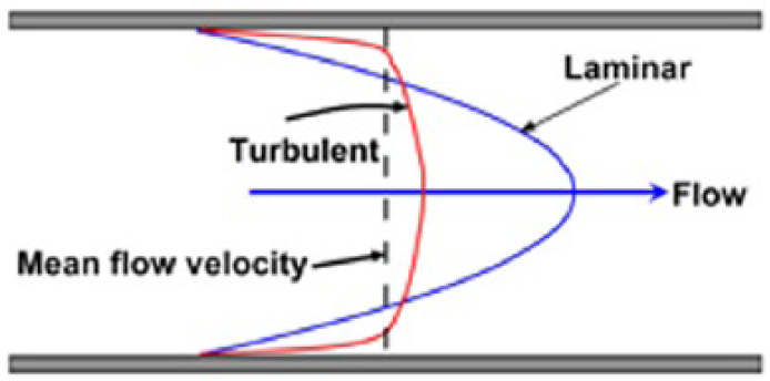
Fluid flow profile
Laminar flow (Re < 2000) occurs at low fluid velocity in which the fluid tends to form parallel layers across the pipe diameter. This results in a parabolic velocity profile across the pipe.
Transitional flow (Re > 2000 < 10,000) occurs as the fluid velocity increases, causing mixing between the layers. The profile may vary between the laminar and turbulent shapes.
Turbulent flow (Re > 10,000) occurs at higher fluid velocity. The laminar layers break down and form eddies and whorls, which results in a flatter velocity profile and is the most favourable condition for predictable and accurate flow metering.
The ideal installation for flow measurement is one with a large length of smooth straight pipe preceding the measurement point to provide uniform and predictable velocities across the pipe – termed a ‘Fully Developed’ condition. In the majority of installations, the flow is turbulent and the condition is referred to as ‘Fully Developed Turbulent Flow’, which is well understood, having been documented following extensive test work and by using a suitable flow element, the mean volumetric flow within the pipe obtained.
However, if there is a disturbance to the flow upstream of the measuring point, such as a bend, a valve or a change in pipe diameter, then the profile will not be fully developed, and the installed flow meter result will not be predictable.
B. Theory
Bernoulli’s theorem applies the law of conservation of energy to the flow of fluids in a conduit and states:
Total energy at any point = Velocity Head + Elevation Head + Pressure Head

where v is the fluid velocity along the streamline (m/s); g is the acceleration due to gravity on earth (9.81 m/s2); h is the elevation above reference (m); p is the pressure, Pascal (kg/m s2) and ρ is the fluid density (kg/m3).
Check the following equation for consistency of units
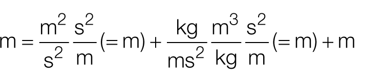
If friction losses are neglected and no energy is added (by pumps) or removed (by turbines), the equation will be constant for any point in the fluid. This is not the case in practice, so an energy balance between two points 1 and 2, allowing for pipe friction (hL), becomes

The continuity equation for incompressible flow provides the following relationship for a change in pipe cross sectional area between two points 1 and 2

substituting for diameter becomes


where d is the orifice diameter and β is the orifice diameter to pipe internal diameter ratio
The above relationships demonstrate that when a fluid flows through an orifice, the velocity increases and the downstream pressure decreases and generates a DP to maintain the energy balance. This is the basic principle on which all differential flow meters are based. All practical formulae for the study of the flow of fluids are derived from these relationships, thus.
Rate of flow of any fluid through an orifice or nozzle neglecting velocity of approach is given by

Correcting for velocity of approach which can have a significant effect
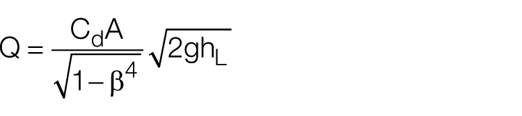
The flow coefficient C is defined to eliminate for calculation of the velocity of approach
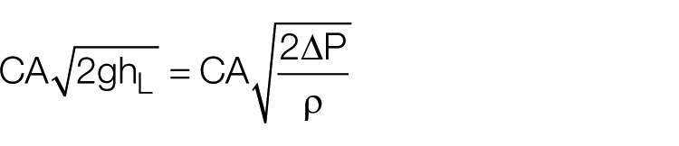
where Cd is the discharge coefficient; C is the flow coefficient, discharge coefficient corrected for velocity of approach factor and hL the measured differential
IV. Types of DP Flow Meters
This group of flow meter includes orifice plates, flow nozzles wedges and venturi tubes, all of which are insertion devices that create unrecovered pressure loss as shown in Figure 3 .
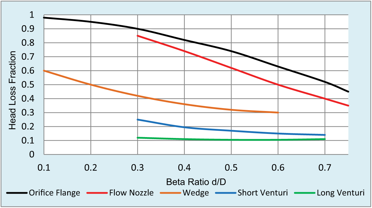
Device head loss versus beta d/D
Other meters using this basic principle include wedge and target meters. Pitot tubes and fan air inlet cones are also in this category and create minimal resistance to flow. Centrifugal force is used for the pipe elbow meter.
All of these primary devices, with the exception of the target meter, are connected to the measuring instrumentation using impulse tubing which is subject to blockages when applied to difficult fluids that may form or contain solids. To overcome this, the transmitter can be close coupled to the element as shown in Figure 4 or fitted with remote seals that isolate the process fluid from the transmitter without affecting accuracy, provided the connecting capillaries are of the same length and experience the same ambient temperature.

In this type of application, segmental orifices may be considered but are not generally recommended as more suitable methods are now available which will be discussed in Tech Talk 6 Part 2. In general, these devices should only be considered for use on clean single-phase fluids.
Valve manifolds are available in 3-valve ( Figure 4 ) and 5-valve configurations and are suitable for most applications, providing an ideal low-cost solution for connecting a transmitter to its impulse lines. The 3-valve configuration provides span and zero calibration, with additional ports available to connect test instruments. The 5-valve configuration provides the additional ports for draining or purging of the impulse lines.
The basics of flow metering using square edged, concentric orifice plates are described below. ISO 5167-2:2003 and other equivalent National or International Standards should be consulted with respect to the design and installation of the other types of metering elements listed above.
A. Square Edge Orifice Plate
The most common form is the concentric orifice which can be supplied with a drain hole near the bottom of the plate when handling wet gases, or a vent hole near the top of the plate for liquids with entrained gas ( Figure 5 ). Eccentric orifice plate construction can provide for full drainage or venting. Integral orifice assemblies, supplied within a ‘metering pipe section’, are available for the measurement of flow through small diameter pipes.

Square edge orifice plate
The orifice plate (primary element) is available in a variety of materials of construction and is a relatively inexpensive device. However, the total installation involving primary isolation valves, impulse tubing and valve manifolds adds considerable cost to the design, installation and maintenance activities.
The maximum flow rangeability ratio is in the region of 3:1 with moderate accuracies of 2%–4% of full-scale reading. This can be improved by flow meter calibration. In some applications, such as wet steam, the sharp edge and bore may degrade over time.
B. Flow Nozzle
Flow nozzles ( Figure 6 ) have an inlet with a streamlined contour making them suitable for use at high fluid velocities and are more resistant to erosion than the orifice plate. For a given diameter and DP, they will pass almost 65% more flow. They can be used on non-homogeneous fluids, provided large percentages of solids are not present. For pipe sizes 150–300 mm and Re > 33000 with β ratios in the range 0.3–0.7, test data show standard deviation is ±0.475%. For applications requiring precision, flow nozzles for pipe sizes less than 150 mm should be flow calibrated.

Flow nozzle
Flow nozzles come in three types: ISA 1932 nozzle, the long radius nozzle and the venturi nozzle, which combines aspects of the other two.
C. Venturi Tube
The classical venturi tube ( Figure 7 ) is streamlined at both entrance and exit. Variations in the outlet cone dimensions have little effect on the discharge coefficient and may be truncated considerably on applications having low β ratios. Pressure loss is minimal, making it a good choice when little pressure head is available. Rangeability is less than 6:1, with accuracy of ±1%–2% of full-scale reading. Viscosity effects on accuracy are high. Flow must be turbulent (Re > 10,000). This element is considerably more expensive than orifice plates but is used extensively in water and wastewater applications, being able to handle dirty fluids.

Venturi tube
D. Wedge Flow Tube
This element consists of a V-shaped restriction formed into the meter body ( Figure 8 ). The wedge provides a segmental orifice plate profile to the incoming fluid. This restriction creates a DP in proportion to the square of the volumetric flow rate. The wedge restriction has no critical surface dimensions, or sharp edges, that will affect measurement accuracy as the result of wear.

Wedge flow tube
Although more expensive than an orifice plate. This device can handle dirty fluids and is generally suitable for most liquids, gas and steam. It can be used to measure bi-directional flow and handles fluids with a Re as low as 500. The slanted faces of the wedge provide self-scouring action and minimise damage from impact with entrained material. Its rangeability of 8:1 is relatively high for a DP element, and accuracies are possible up to ±0.5% of full-scale reading.
E. Target Meter
The target flow meter ( Figure 9 ) is suitable for difficult-to-meter fluids. The primary element is a supported circular disc that forms an annular orifice to the flowing fluid and is directly connected to the transmitter. β ratios are in the range 0.5–0.8 depending on fluid velocity and properties. At β ratios around 0.8, viscosity correction variations are considerably less than for orifice plates. Repeatability is good, and high accuracy is obtainable using flow calibration

Target meter
F. Pipe Elbow Meter
When fluid flows through a pipe elbow, the centrifugal force generated creates a pressure differential between the inner and outer radii of the elbow. Pressure taps in the elbow measure this differential, which is proportional to the elbow’s radius. Elbow taps located at 22.5° from the inlet ( Figure 10 ) result in a more stable and reliable reading than if placed at 45° and are less affected by approach conditions. Pipe elbow meters ( Figure 10 ) are used where lack of space prohibits use of other types of flow meters and provide a reproducible, if not accurate result. This method can measure bi-directional flow and is used extensively on dyeing machinery.

Pipe elbow meter
G. Pitot Tube
Pitot tube ( Figure 11 ) is a low-cost element used to measure fluid flow, especially air flow in ventilation and heating, ventilation and air conditioning (HVAC) systems and also used to measure the speed of aero planes. This element works by comparing the pressure created by the kinetic energy of the fluid flow with the static pressure. It is not suitable for dirty fluids and has limited rangeability. As an insertion meter, the pitot tube makes a measurement at a single point within the pipeline or duct, so positioning is sensitive to the velocity profile. Positioning problems can be avoided by using the averaging pitot tube, which contains multiple orifices.

Pitot tube
H. Fan Inlet Cone
Measuring variable air flow accurately on fan discharges requires long straight lengths, which are frequently impractical, or flow straighteners, which are expensive, to give a reproducible and stable velocity profile ( Figure 12 ). A recognised method, to ISO5801:1997, measures the air flow at the fan inlet using a calibrated cone with the configuration shown in Figure 12 . This method is particularly useful on combustion air installations which are often space limited.

Fan inlet cone
V. Concentric Sharp Edge Orifice Plate Flow Meter
Figure 13 shows the fluid pressure profile through a concentric orifice where the point of maximum velocity occurs downstream at the ‘vena contracta’. It can be seen that the measured DP is dependent on the selection of pressure tap position, and so the flow coefficient (C) depends partly on the tap positions. The permanent pressure loss depends on the β ratio and varies from 62% to 90% of total pressure drop for β ratios in the range 0.6–0.3.

Orifice plate taps and pressure profile
There are three standard positions covered by ISO 5167-2:2003 and other major standards as follows:
Corner taps placed immediately upstream and downstream of the plate, convenient when the plate is provided with an orifice plate;
Orifice plate carrier assembly incorporating the taps;
D and D/2 taps or radius taps placed one pipe diameter upstream and half a pipe diameter downstream of the orifice plate; these can be installed by welding bosses to the pipe and are generally used on large bore pipes where the cost of an orifice plate carrier would be prohibitive;
Flange taps placed 1 in (25.4 mm) upstream and downstream of the orifice plate, normally incorporated within specialised pipe flanges.
Other types include the following:
Pipe taps 2½D and 8D taps placed 2.5 pipe diameters upstream and 8 diameters downstream, at which point the measured differential is equal to the unrecoverable pressure loss caused by the orifice; this may be used to verify the performance of flow restriction orifices;
Vena contracta taps placed one pipe diameter upstream and 0.3–0.9 diameters downstream, depending on the orifice plate type and its size relative to the pipe in the plane of minimum fluid pressure.
The flow coefficient C is influenced by the fluid flow Reynolds number and the orifice plate β ratio selected during sizing as shown by the curves in Figures 14 and 15 .

Flow coefficient C square edge orifices (Reference Crane 410M)

Flow coefficient C square edge orifices (Reference Crane 410M)
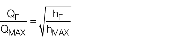
This indicates that acceptable β ratios for fully turbulent flow are in the range 0.2–0.6. For β > 0.6, the viscosity effects are magnified combined with upstream sensitivity to piping configurations. The measured meter DP (hF) is proportional to the actual flow rate (QF) squared as per the relationship
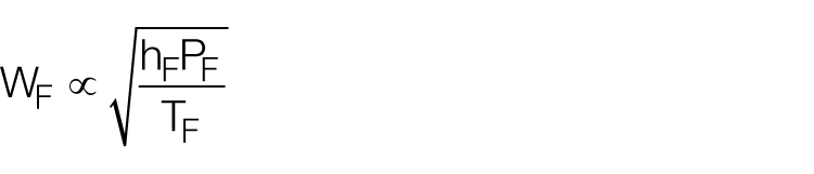
Compressible gas flows can be corrected to give mass rate (WF) from the flowing pressure (PF) and temperature (TF) by using the following
Conventional meter full-scale flow calibrations are set in the range 2500–5000 mm wg for liquids and 750–1250 mm wg for gases and are adjusted to provide an acceptable β ratio.
Due to the square root relationship, the rangeability ratios are limited to the 3:1 to 4:1 region. This can be extended by applying wide range flow metering techniques using differently ranged and switched DP transmitters. Correctly designed and installed, the flow rate can often be derived with an acceptably low uncertainty (typically ±3% of reading) by taking the square root of the DP across the orifice plate installation pressure taps and applying an appropriate constant.
Most manufacturers of orifice plates, plate carriers and metering pipe units use sizing calculation software based on one of the several available International Standards which has been derived using experimental data.
Historically, orifice plates were used to measure difficult non-homogeneous fluids exhibiting two-phase flow or having varying physical conditions such as viscosity, because no other methods were available. Various design adaptations and techniques were developed by varying the orifice bore location and shape and the purging of impulse lines with process compatible clean fluids. Now, the generally preferred practice is to use orifice plates on clean single-phase fluids or those only containing small quantities of a differing phase.
A. Impulse Pipe Installation Arrangements
Standard ISO 5167-2:2003 gives detailed guidelines for the installation of impulse pipes between the orifice plate pressure taps and a DP indicator or transmitter. In summary,
Keep impulse lines as short as is practical and both of the same pipe bore;
Install primary isolation valves at the pressure tap points; this will facilitate maintenance;
Where impulse pipes must slope up or down to the instrument, the minimum slope should be 1 in 12.
B. For Liquids
Install pressure taps either on the horizontal centre line of the pipe or at 60° upwards slope from the centre line.
For instruments above or below the pipeline level, slope the impulse pipes to the instrument ensuring that the same static head will occur on both impulse lines.
Consider the installation of vent valves to purge gas bubbles at the highest point of the impulse lines and drain valves at the lowest point. Purging for several minutes on process start up is recommended to eliminate gas bubbles from the lines.
C. For Gases
For dry gas, the orientation of pressure taps is usually not critical; however, if condensation is possible, the pressure taps should be located on the top centre line of the pipe and impulse lines arranged with a minimum slope of 1 in 12 such that any condensate flows back to the pipe.
D. For Steam
Install pressure taps on the side of the pipe. Cooling chambers are required so that vapour can condense and form a constant head cold barrier between the pipe and the instrument. Mounting of the cooling chambers is critical in order to ensure an equal head in each impulse line. Cooling chambers and impulse lines must not be lagged; however, thermal protection in the form of a mechanical guard is essential. Calibration of the transmitter should, if practical, be carried out under ‘hot’ conditions to minimise low scale offset error.
VI. Pipe Line Design Considerations
The Instrumentation Engineer must be involved when pipelines incorporating flow meters are being designed to ensure that adequate pressure is provided and that the pipe is sized to give an acceptable fluid velocity through the meter. Accessibility for cabling and maintenance purposes also requires consideration. Industry practice for initial design is based on economic velocity or allowable pressure drops as shown in Table 1 .
Reasonable velocities for flow of fluids through pipes (Reference Crane 410M)

The geometry upstream and downstream of the flow meter can, depending on the type of meter chosen, have a marked effect on the metering accuracy. Disturbance of the fluid flow profile can be caused by upstream obstructions such as a thermowell, gasket protrusion, badly dressed pressure tapping welds or in-line valves. Swirl can cause very large metering errors which are caused by one or more bends in the pipeline, the worst cases being where changes in the pipeline plane exist. Figure 16 shows typical upstream straight pipe diameter requirements, depending on the disturbance, for concentric orifice plates. For detailed application guidance, reference should be made to data contained within Standard ISO 5167-2:2003.

Orifice plate approach conditions (Reference LK Spink)
Ideally, manufacturers’ recommendations regarding upstream and downstream straight pipe lengths should be followed. If this is not practical, consideration should be given to flow straightening and/or flow conditioning in-line equipment. Such devices, which include tube bundles and perforated plates, can reduce swirl and in some cases improve the flow profile. Specialist advice should be sought in the application of these devices.
DP flow meters (orifice plates, venturi tubes, flow nozzles, wedge meters and pitot tubes) are especially vulnerable to inaccuracy resulting from poor pipeline design. In cases where temperature and pressure compensation instruments are to be installed for mass flow measurement compensation, the pressure instrument connection should be teed from the upstream DP measurement tapping and the temperature thermowell installed at between 5 and 15 pipe internal diameters downstream of the metering position.
VII. Specifying Flow Meters
The use of the manufacturer’s data sheet or an equivalent is strongly recommended in order to transmit all information relative to the process conditions, reference conditions and pipeline design, required for the sizing calculation. An understanding of the nature and dynamics of the fluid flow to be measured is essential in selecting a flow meter. Below are some of the main considerations.
A. All Fluids
Flow rate – maximum, normal and minimum (to determine the turn-down ratio);
Volume or mass flow measurement;
Viscosity at flowing conditions;
Laminar, transitional or turbulent flow;
Temperature and pressure – maximum, normal and minimum;
Material of construction;
Design pressure and temperature.
B. Liquids
Specific gravity, solids in suspension (nature and percent of flow), conductivity, corrosion and erosion properties;
Single- or two-phase flow.
C. Gases
Gas mixture composition, moisture content, molecular weight;
Density, absolute pressure and absolute temperature;
Flow rate reference conditions.
D. Steam
Saturation temperature or °Kelvin of superheat
Footnotes
Acknowledgements
The authors wish to thank Mr Greg Livelli of ABB Instrumentation, USA, for permission to use material from his paper ‘Flow metering theory and practice’.
Funding
This research received no specific grant from any funding agency in the public, commercial or not-for-profit sectors.