



Abstract

Liquid-level measurement is often the key to safe and reliable process plant operation and covers both point and continuous level measurement applications. It is used in a wide variety of applications, including storage tanks, surge tanks, pump wells, boiler drums, flash vessels, distillation column reflux drums and reboilers.
Level measurement serves a number of purposes, including
Overfill protection;
Pump dry running protection;
Boiler steam drum critical level monitoring;
Stock control and custody metering.
Liquid-level measurement is the detection of the phase split between vapour/liquid, liquid/liquid, vapour/solid and even liquid/solid interface. A reliable outcome will typically depend on the phase conditions and with certain methods being relatively consistent under all process conditions. Unfortunately, the importance of level control is not always appreciated. Failure to measure level reliably has resulted in some of the most serious industrial accidents, including those at the Buncefield, United Kingdom, fuel storage depot and British Petroleum’s (BP) Texas City refinery.
The technologies to measure and transmit process level have evolved significantly since the 1960s. Impulse lines, used to connect instruments to the process, appear less frequently on new installations and are being replaced on existing ones; if used, they require specialist knowledge during design, installation and maintenance for reliable measurement.
I. Data Transmission
Sensor and transmitter developments coupled with data transmission innovation offer low installation costs, simplified maintenance and enhanced plant performance. Smart transmitters provide bi-directional digital communication and diagnostics capability. With the Highway Addressable Remote Transducer (HART®) protocol, the 4–20 mA and HART digital signals are transmitted over the same dedicated wiring, providing a centralised capability to configure, calibrate, characterise and diagnose devices together with reporting capability. Data can be captured from multi-parameter devices without additional hardware, providing predictive maintenance capability.
The development of Fieldbus digital communication allows several field devices to be connected using a single cable bus structure. This multi-loop capability potentially reduces cabling, installation time and cost. Fieldbus is a device level network. There are several protocols available, with Modbus®, PROFIBUS PA and Fieldbus FOUNDATION™ being the most common.
II. Functional Safety
Functional Safety relates to the overall safety of a system or piece of equipment that depends on the system or equipment operating correctly in response to its inputs, including the safe management of likely operator errors, hardware and software failures and environmental changes. IEC 61508 and IEC 61511 are the generic Functional Safety Standards which cover the design and whole lifecycle of electrical, electronic or programmable electronic (E/E/PE) systems and products. Conformance with these standards requires designers to select sensors and systems, which when taken together present a probability of failure on demand that falls within the limits of the calculated Safety Integrity Level (SIL) for the measurement/control loop.
On critical applications, it is common practice to install two or more redundant level systems. Redundancy implies that no single equipment failure will lead to loss of all functionality. A common cause failure may mean that all redundant systems may fail at the same time. Systems using either identical measurement methods, sensors or a common monitoring system will typically be more susceptible to common cause failure.
A common solution for vessel liquid level monitoring and control is to install a continuous monitoring level transmitter to control the inflow or outflow of the vessel’s contents in conjunction with a controller and control valve or variable speed pump. In some applications, such as surge tanks, the level is allowed to float between upper and lower limits and will typically use Proportional mode–only control. If level is to be controlled at a fixed point Proportional and Integral modes are required to eliminate steady state error. Level is frequently a noisy measurement, so Derivative mode is not usually suitable as it operates on rate of measurement change.
High- and low-level alarms can be derived from the analogue level signal. Additional alarms and trips can then be provided by point-level switches which are hard wired to stop a pump or close a valve as appropriate.
Inherent in functional safety protection (and indeed all protective level switch circuits) is the principle of fail-safe design. Both high- and low-level switches should open circuit in the event of an alarm or trip condition occurring. However, the total system needs in-depth study to determine the potential for failure to danger scenarios and to ensure calibration and trip testing facilities and procedures are acceptable.
Frequency of testing for satisfactory operation can have a major impact on the system reliability, although in situ testing of level instrumentation is often difficult to achieve due to problems in driving the process to the condition required, for example, high level in a vessel. The use of real-time diagnostics to ensure sensor and circuit integrity can greatly improve the overall loop reliability.
III. Application Considerations
It is essential to fully understand the physical property variations of the process fluid and the phase changes that may occur within the process during normal and abnormal conditions. Certain types of sensor performance can be affected by surface conditions such as foaming or turbulence due to process boiling, the method of filling, vessel agitation or interference from other vessel internal components. Consideration should be given to mounting sensors in a stilling well or external cage.
Measurement instrumentation selection and specification should take into account
Compatibility of wetted parts with the process fluid;
Operating pressure and temperature limits;
Requirements of calibration and functional testing;
SIL rating and certification where applicable;
Hazardous area (ATEX) certification where applicable;
Ingress protection (IP) rating to suit environmental conditions.
IV. Hydrostatic Methods
This method may be employed for continuous, indirect level measurement and measures the pressure due to liquid level and density plus, for pressurised vessels, the vapour space pressure. For non-pressurised vessels, the sensor measures the pressure difference between the hydrostatic head pressure and atmospheric pressure. Instruments can be flanged mounted, suspended in a stilling well or of the rod insertion type, the latter not being recommended for turbulent conditions without extra support or a stilling well. Temperature change will affect the measurement accuracy.
Simplified level equation

where h is the height of the liquid column (m), P is the pressure exerted by the equivalent liquid column of water (kg/m2) and ρ is the density of liquid (kg/m3).
Figure 1 shows a typical installation for a pressurised vessel using diaphragm seals, although consideration should be given to providing primary isolation and calibration facilities (valve manifolds) at the vessel connections to facilitate maintenance.
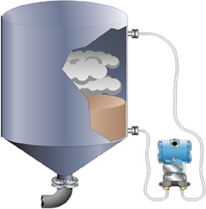
Hydrostatic level transmitter with diaphragm seals
The bubbler method ( Figure 2 ) measures the back pressure created by the liquid level hydrostatic head. This is one of the earliest methods of continuous level measurement, which still finds frequent application on vented vessels for clean fluids and in applications where access for maintenance is not practical such as the process cells in nuclear waste treatment plants. This method should not be used on process fluids prone to blockages, for example, crystallisation, polymerisation or deposition. The method can be used on pressurised vessels, but the low-pressure connection requires careful consideration in design to avoid collection of process fluid and to ensure stable reproducible pressure conditions. Other methods may be more appropriate.

Bubbler installation
Instrument air or another gas such as nitrogen is bubbled through a dip tube, the flow typically being controlled by a needle valve and variable area flow meter combination. A differential pressure transmitter connected to the dip tube, as close as possible to the nozzle, detects a pressure proportional to the hydrostatic head. Point-level detection can be accomplished by using a pressure switch in place of the transmitter.
V. Displacement Methods
The displacer continuous or point-level method measures the change in level via a torque tube or lever arrangement that senses the changes in up thrust on the displacer. The continuous measuring range is set by the displacer length immersed in the tank or external cage ( Figure 3 ), which is preferable on noisy applications. The point method uses a float with the range being limited by the length of the float arm. This mechanical method may be used where the density of the fluid remains constant; there is no risk of adhesion of the fluid to the displacer and where the frequency of operation does not present a wear out problem.

Displacement-level transmitter with external cage
Variations of this method include a tube incorporating a magnetic float which activates integral visual indication and externally mounted reed switches. Point-level measurement may also employ float switches either mounted direct into the vessel via a mounting flange or in an external cage. Level switches also exist for mounting through a top flange on a vessel and employ a combination of ball float, suspension rod and switch lever.
VI. Nucleonic Method
The nucleonic point or continuous, non-contact, level method measures the signal strength of a radioactive (gamma) source beamed across a vessel ( Figure 4 ). It is generally independent of fluid properties such as pressure and temperature, although variations in density may cause inaccuracy. Typical measurement range is 0.24–3.36 m. Point-level measurement can be achieved by mounting a nuclear source and detector/switch on diagonally opposite sides of a vessel.

Continuous nucleonic–level measurement
This method has been applied successfully on difficult applications such as measuring level in flash vessels and distillation column reboilers under all temperature and pressure conditions and in detecting liquid interfaces on three phase separators. Users should note that a license is required by the owner of a radioactive source.
VII. Radar Method
The radar point or continuous level method measures the travel time of an impulse transmitted and reflected from the liquid surface. Interference echoes resulting from tank internals and agitators can be suppressed and signals characterised to give liquid volume. The radar antenna ( Figure 5 ) has no contact with the liquid but is exposed to head space conditions where the fluid may coat the antenna, affecting its operation. Reflectivity requires the liquid dielectric constant (ϵR) to be ≥1.4 (hydrocarbons 1.9–4.0, organic solvents 4.0–10 and conductive liquids >10). The antenna and signal conditions are adjusted to suit the process, with guided radar ( Figure 6 ) being used for low ϵR and turbulent conditions. The method is suitable for custody transfer with accuracy ±0.5 mm being claimed. A wide range of antennae are available operating at differing microwave frequencies to suit the application.
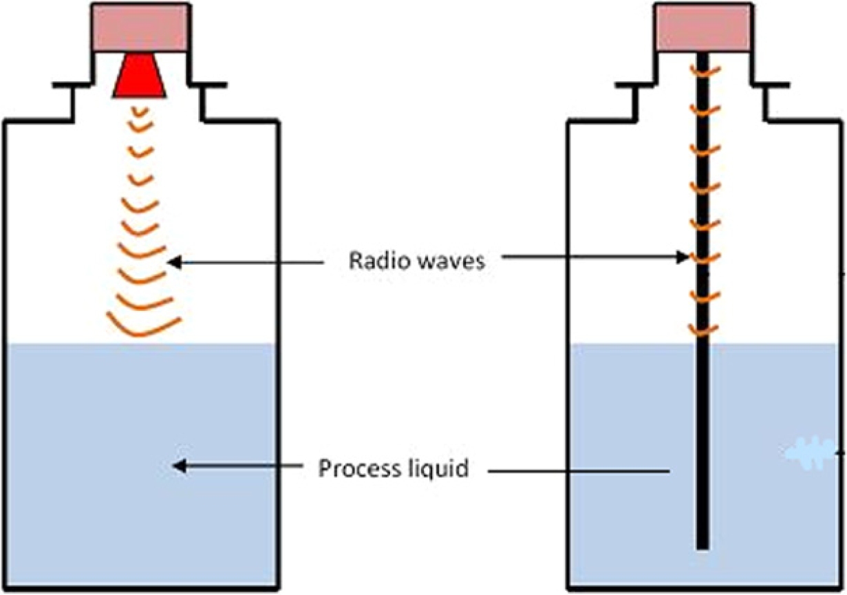
Non-contact radar liquid level measurement
VIII. Capacitance Method
The capacitance point or continuous level method is suitable for liquids which can act as dielectrics. The measurement is more sensitive when the difference in dielectric constant δϵR of the liquid and the vapour space or between the two liquids is higher. Special designs, involving coated and twin probes, are used when δϵR<1.0, conductivities >100 µmho or to overcome probe build-up and the vessel coating or material is non-conducting. Accuracy is dependent on fluid properties, so the technique is not recommended for changing conditions.
IX. Ultrasonic Method
The ultrasonic point or continuous level measurement ( Figure 7 ) is based on the time-of-flight principle. A sensor emits and detects ultrasonic pulses in the 20–200 kHz range, which are reflected from the surface of the liquid. The method is not affected by ϵR, conductivity, density or humidity, although foaming can present problems.
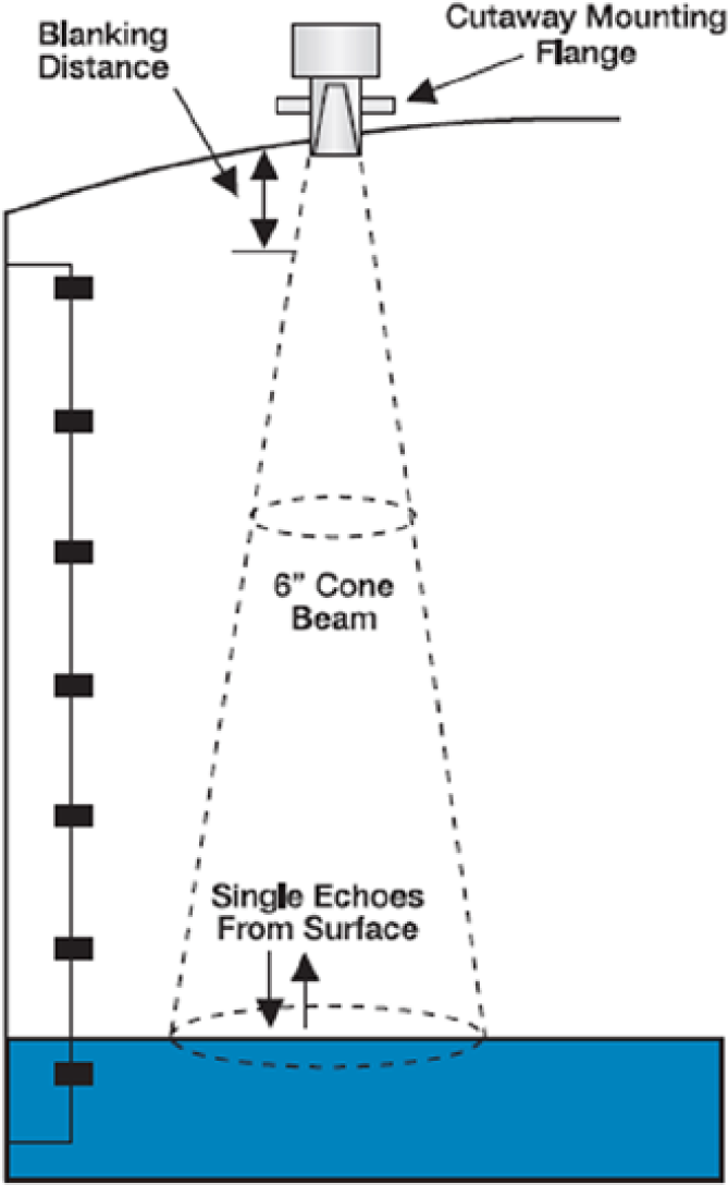
Ultrasonic level transmitter installation
This method is also affected by variations in the gas phase conditions involving temperature variations (which can be compensated for), condensation and material coating on the instrument face. The installation requires careful consideration to avoid interference echoes developed by vessel edges, welded joints, internal components and agitators, although it may be possible to filter these. The beam angle must not impinge on the vessel internal wall over the measuring range, and the face of the transmitter must be parallel with the surface of the fluid being detected. The transmission time characteristics of the sensor determine a minimum allowable distance between the sensor and the upper level of the transmitter calibration.
X. Weighing Method
Load cells, based on strain gauge or piezoresistive sensors, measure the weight of the process vessel plus its contents. Individual load cell accuracy of 0.03% full scale is achievable, but overall performance is dependent on correct installation practices preventing external forces due to wind, associated piping and equipment. For vessels with jackets, agitation and complex piping, it may be difficult to obtain an acceptable accuracy. When the container can be totally isolated, as in final dispensing and filling applications, precision weighing can be achieved. Level measurement is only dependable when the density of the liquid remains constant.
XI. Vibrating Tuning Fork Method
The vibrating tuning fork principle is used to detect point liquid and solids level. The method is suitable for most liquid applications, with some devices being tolerant of material build-up and air bubbles. Instruments are available for a wide variety of pressure and temperature applications. The tuning fork may be side mounted in a vessel or suspended from a top flange ( Figure 8 ). The fork is excited at its resonant frequency by the piezoelectric method. The frequency or amplitude of the oscillations changes when it is covered by the process fluid. The change is detected and translated into a switching action.

Top and side mounted tuning fork
XII. Conductivity Method
The conductivity point–level method ( Figure 9 ) requires a liquid conductivity >0.1 µmho and is frequently used on utility and effluent pump control systems. Other applications include overfill protection, double-skinned tank interstitial leak detection and boiler drum–level detection. Non-metallic vessels will require an additional ‘reference’ electrode. Conductivity-level sensors provide an inexpensive, reliable, maintenance-free point-level detection for clean process fluids.

Conductivity-level measurement
Level measurement selection charts
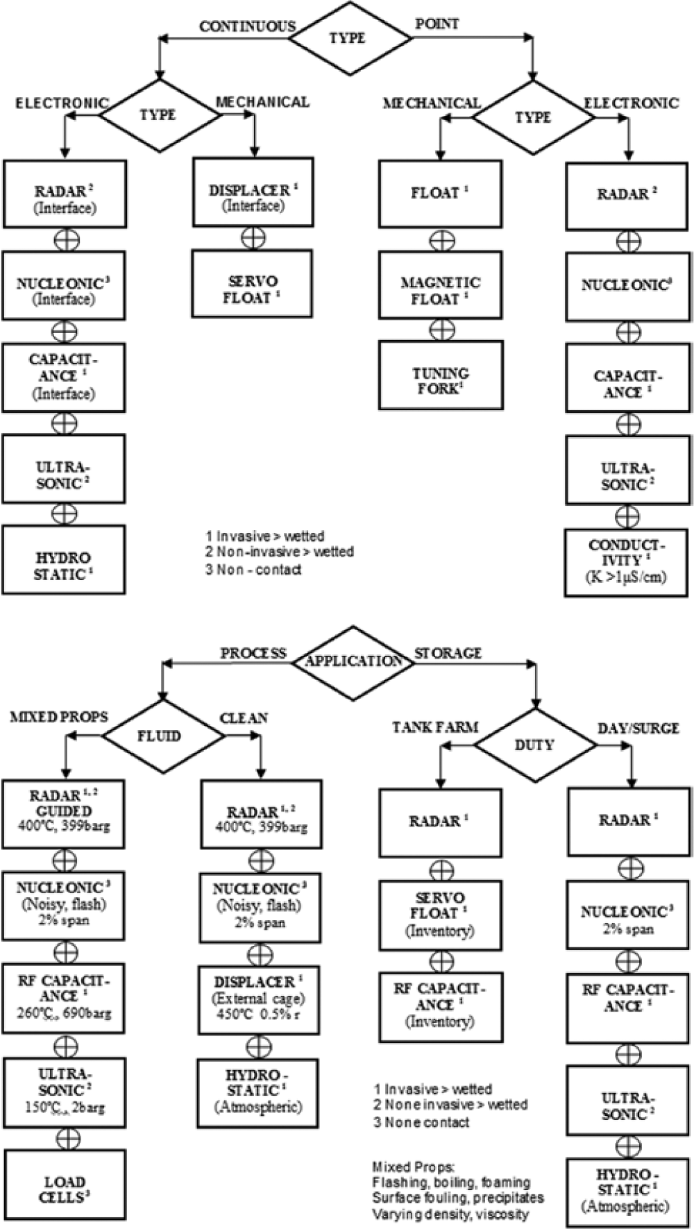
Footnotes
Funding
This research received no specific grant from any funding agency in the public, commercial or not-for-profit sectors.