
Abstract
This work describes numerical modelling of underground hydrocarbon storage tank dip gauge. The work was carried out at the request of a petroleum company faced with predicament, whereby three underground tanks, for the storage of hydrocarbon products, namely, Petroleum Motor Spirits, Automotive Gas Oil, and Dual Purpose Kerosene, were fully installed and buried in the earth without provision for the fluid measuring gauge. The objective was to design and fabricate a dip gauge with the design capacity of measuring up to 30,000 L of hydrocarbon from the underground storage tank. To achieve the objective of designing an accurate and reliable gauge, mathematical analysis of the available data of tanks was carried out using Newton–Raphson iteration method. A model dip gauge was designed and calibrated with the results of mathematical analysis. The dip gauge was designed with measurement capability between the range of 200–15,886 L and 400–31,765 L of hydrocarbon in the smaller and bigger tanks, respectively. Aluminium alloy 6063-T6 was used for fabrication of the gauge on account of its excellent strength and good corrosion resistance in relevant hydrocarbon environment.
I. Introduction
Dip gauge is often used in petroleum-filling stations in Nigeria to measure the depth and the volume of hydrocarbon left in the underground storage tank. 1 While there are host of new fluid measuring apparatus designed based on floatation and ultrasonic sound wave with sophisticated electronic devices in existence today,2–5 it is not uncommon to find dip gauges still being used in most Nigerian petrol-filling stations. This is partly because of its simplicity and reliability. Dip gauges are comparatively cheaper to design, and durable and affordable to end users than sophisticated electronic devices in the market.
This particular work was carried out at the request of Jibeco Petroleum Nigeria Limited, Osi, Kwara State, Nigeria. During the construction of the filling station, the three underground storage tanks installed at the station were sourced from the local fabricator without provision for the dip gauges. After the station was commissioned, with the three tanks buried in the earth and the concrete flooring completed, the management was faced with challenges of getting accurate measurement of the hydrocarbon in the buried tanks from procurement till the end of sale, particularly for daily stock taking.
Some of the challenges the company faced on acquiring a reliable dip gauge for the buried tanks included the cost of concrete floor removal, exhumation of tanks, and re-flooring afterwards, sales disruption and customer dissatisfaction, and not the least, the damage to anti corrosion paint on the tank after exhuming from ground. A report 6 shows that significant damage to the environment may occur from small discharge as little as half a gallon of hydrocarbon per day from corroded or poorly designed tank. An alternative method of calibration without exhumation of the tank commonly used in this scenario requires incremental filling of buried tank with known volume of hydrocarbon and marking the depth of the fluid on the dip gauge. 1 This method is particularly cumbersome and less accurate as the turbulence caused by fluid discharge into the tank may undermine accurate reading and marking of fluid depth on the dip gauge.
The main objective of this work was to develop numerical model of dip gauge to solve immediate problem facing the company, which is equally adaptable for future application. It is also one of the objectives of this work, to design a dip gauge that is simple and affordable to end user without compromise to accuracy and reliability. These objectives were achieved through the mathematical analysis of available data of underground storage tanks using Newton–Raphson iteration method. 7
II. Methodology
Mild steel has been the most widely used material for fabrication of underground storage tank. 8 Hence, the three horizontal cylindrical tanks involved in the project were fabricated from mild steel, coated with anti-rust paint, and fully buried underground resting on their sides (see Figure 1 ). The installation is obviously different from what is commonly seen at regional fuel depots where semi-buried tanks are installed in upright position. 9 The chemical composition of the mild steel used for fabrication of the buried tanks was not available from the manufacturer.
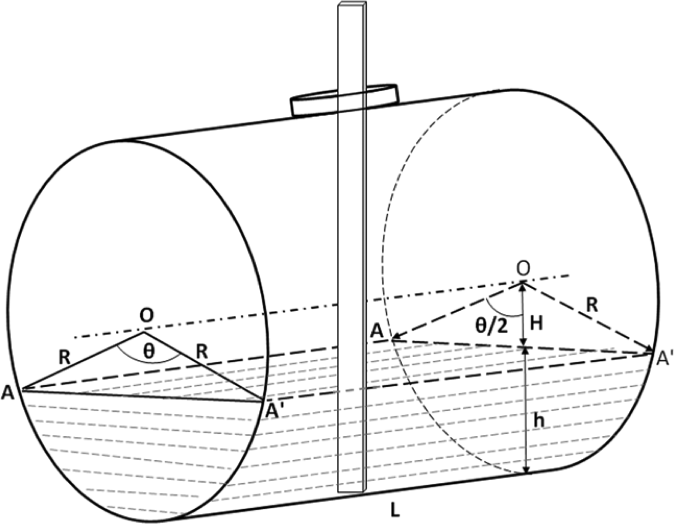
Schematic diagram of the buried tank
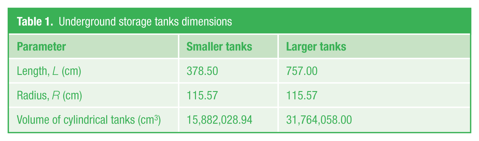
There were two smaller tanks with installed capacity of 15,882 L for the storage of Automotive Gas Oil (AGO) and Dual Purpose Kerosene (DPK) hydrocarbon products. The third larger one with installed capacity of 31,764 L was used for Petroleum Motor Spirits (PMS) storage. These tanks were installed to handle 15,000 and 30,000 L of hydrocarbon, respectively, and the excess volume was designed to cater for the fluid overflow. The dimensions of the smaller and larger tanks are presented in Table 1 .
Underground storage tanks dimensions
The tentative volume of the hydrocarbon in the tanks was calculated from the area of minor segment AA′ and the length of the cylinder occupied by hydrocarbon. While the area of the minor segment AA′ was determined from the following equations:


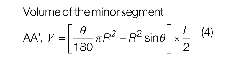
where V is the volume of the minor segment AA′, R is the radius of cylinder, L is the length of cylindrical tank resting on the floor, and θ is the included angle (
Substituting for radius, R and length, L of the tank in equation (4), and solving for the angle θ in equation (5), for a tentative volume, V of hydrocarbon was achieved using differential calculus and Newton–Raphson iteration method.
The ranges of volume measurable in the tank were 200–15,000 L and 400–30,000 L for smaller and larger tanks, respectively. Hence, 200 L (200,000 cm3) was considered as the initial tentative volume of hydrocarbon substituted in equation (5). Using Newton–Raphson iteration method, equation (6) was differentiated with respect to angle θ to obtain equation (7). The Newton–Raphson iteration method suggests that, when


III. Results and Discussion
The tentative volume of hydrocarbon (segment AA′) and the corresponding values of the included angle θ determined using Newton–Raphson iteration method are shown in Table 2 . The calibration of the gauge was done based on the height of hydrocarbon in the tank; determined from tentative volumes (variable) used; radius of the cylindrical tank, R; and included angles θ determined using Newton–Raphson iteration method.
Volume of hydrocarbon in the tanks, the corresponding values of angle θ, and depth of dip gauge
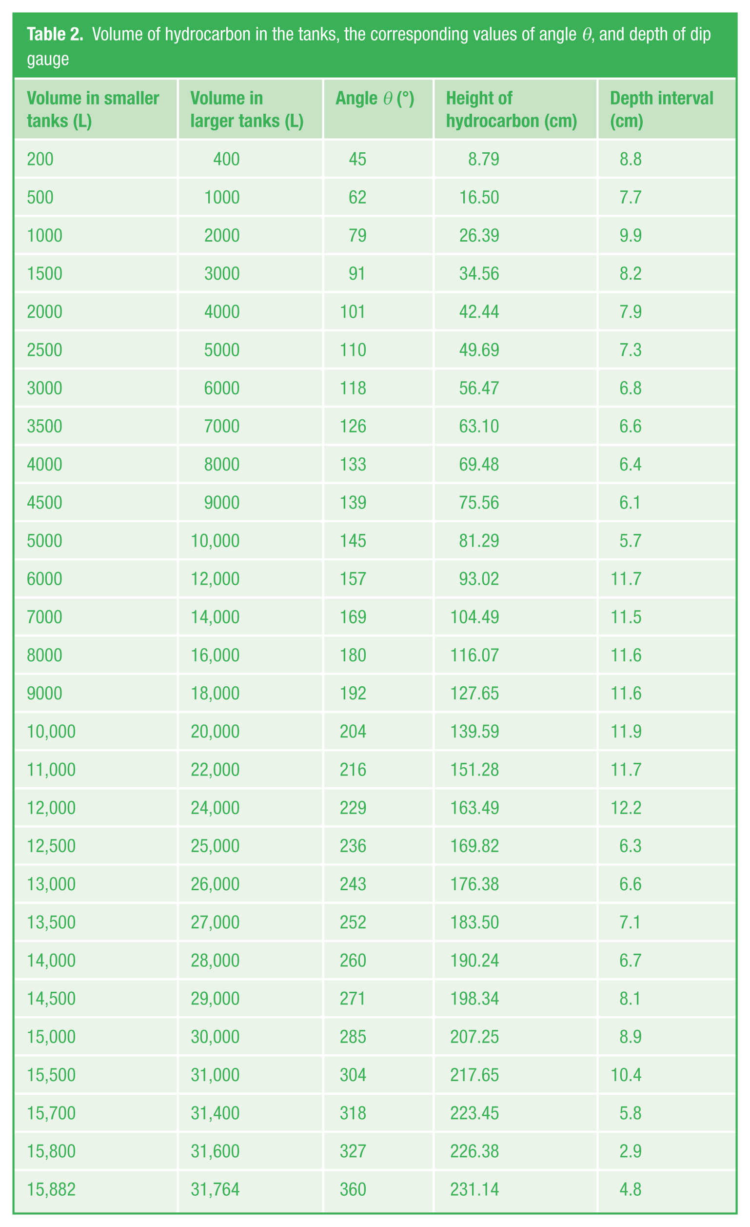
The height of hydrocarbon from the bottom of the cylinder for a given volume on the dip gauge was determined from the geometrical relationships (see Figure 1 ) in line with equation (9). The detail results of the h calculated from equation (9) for various tentative volumes are presented in Table 2
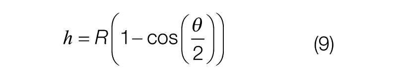
If V = 200 L (200,000 cm3), R = 115.57 cm, θ = 45°, and h1 = 8.79 cm.
IV. Design of Dip Gauge
A. Material used for gauge fabrication
To ensure the dip gauge is durable, careful consideration was put into selection of material for fabrication of the gauge. The aim was to ensure that the gauge was durable without compromise to its integrity over time. Hence, the gauge material must have a considerable amount of strength to ensure it is wear resistant and to prevent warping. 10 It is equally important to ensure the used material used is corrosion resistant in petrochemical environments. The fact that the gauge was to be calibrated and marked by engraving method was a clear indication that careful thought was needed on corrosion resistance of the candidate material.
The material considered for fabrication of the gauge was Alloy 6063-T6, procured from local retailer. The chemical composition of the alloy (wt%) as received, from the data sheet was as follows: Al: 97.5 max, Mg: 0.45–0.9, Si: 0.2–0.6, Fe: 0.35 max, Cr: 0.1 max, Mn: 0.1 max, Ti: 0.1 max, Cu: 0.1 max, and Zn: 0.1 max. Alloy 6063-T6 is known for its light weight and good mechanical properties, but the properties depend to a greater extent on the treatment condition either in temperate or heat-treated condition. Generally, the alloy yield strength ranges from 130 to 214 MPa,11,12 and the corrosion resistance is comparatively good making it suitable for use in hydrocarbon environment. Alloy 6063-T6 has good weldability, although with significant loss of strength, which could be recovered back by heat treatment.
B. Gauge marking and calibration
The alloy 6063-T6 used for the fabrication of the gauge was a rectangular flat bar. The length of the gauge was 300 cm. The gauge was coated with blue paint, which is resistant to hydrocarbon before engraving was carried out. The painting was necessary to enhance the contrast and visibility of the markings on the gauge. The use of paint was to also help minimise the possibility of spark with tank when it is dipped down. 10 It is not uncommon to find in practice, where gauge is permanently installed in underground storage tank.2,13 Considering the plausibility for two dissimilar metals in contact to become susceptible to galvanic corrosion in aqueous environment, the paint used will further help to reduce the risk of galvanic corrosion between the aluminium gauge and steel tank in aqueous solution which may build up from condensation inside the tank. However, Kass et al. 8 suggested from their study that galvanic corrosion was not likely in the absence of water.
With regard to the marking of the gauge, calculated volumes at a predetermined depth were engraved on both sides of the gauge. The volumes were calibrated between 200 and 15,882 L for the two smaller tanks and calibration for the larger tank ranged between 400 and 31,764 L. The schematic diagrams of the model are shown in the Figure 2 . The tanks were designed to keep dead stock of 200 and 400 L of hydrocarbon for the smaller and larger tanks, respectively. Hence, they were both used as the starting point on the dip gauge. The dead stocks were absolutely necessary to prevent suction of impurities and water which may form due to condensation or probable leakage into the tank from the environment. The presence of water in the tank poses a greater risk of microbial induced corrosion and eventually leakage of hydrocarbon to the environment. 8 The standard methods often used for control of corrosion in underground storage tank include sacrificial anode and impressed current. 14
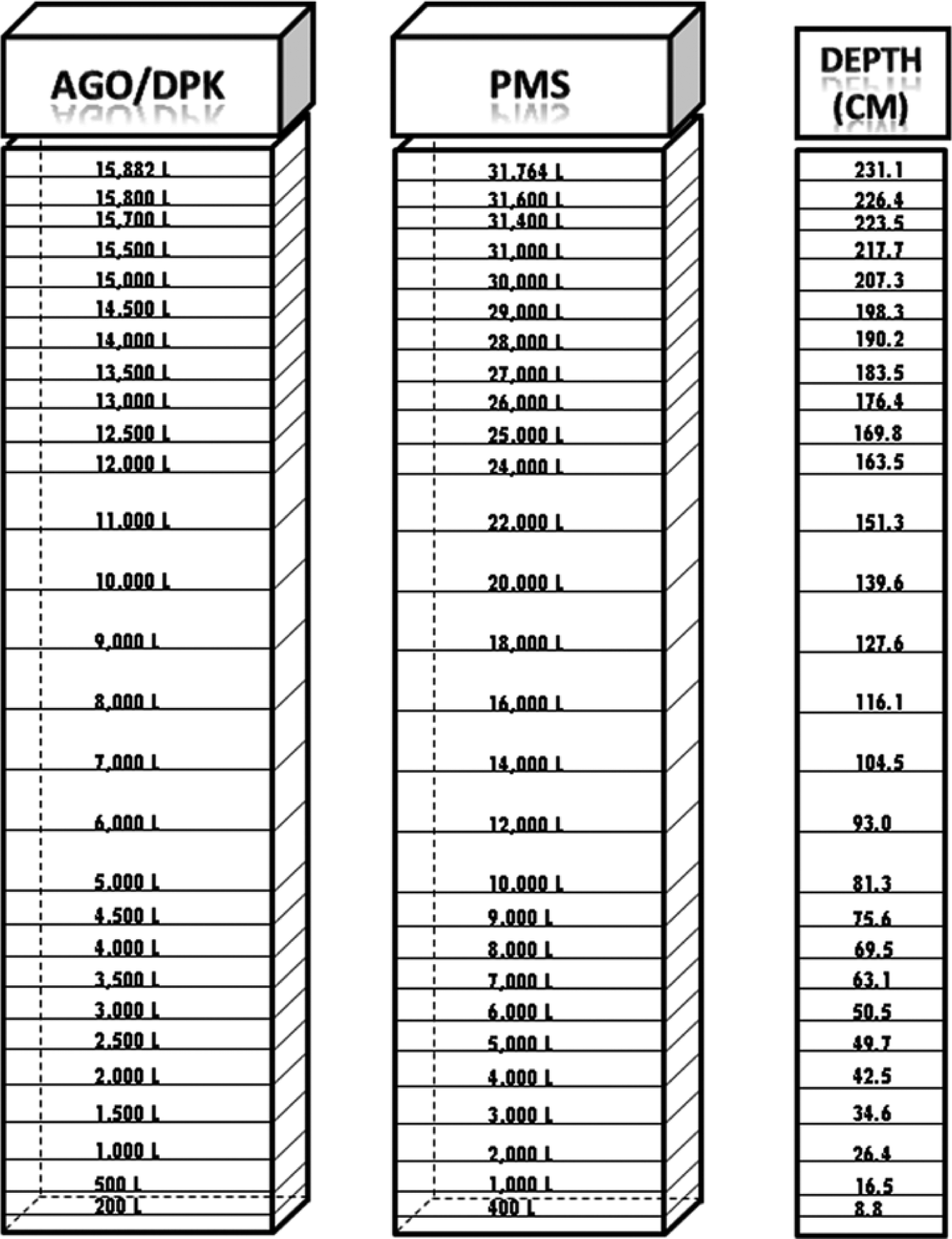
Model gauge designed for the measurement of hydrocarbon (AGO, DPK, and PMS) in underground tanks
The gauge was also capable of detecting the presence of water in the tank if used with water-detection paste. Typical water-detection paste in market often used includes kolor kut or VECOM.15,16 The paste is applied lightly on the gauge before dipping in the tank. The water in the tank reacts with paste and changes its colour clearly indicating the water level in the tank. The accuracy of the measurement reading can be equally improved if the fuel detection paint is smeared around the probable depth of hydrocarbon on the dip gauge. 10
Usually, it is a good practice to gently lower the gauge into tank thereby allowing soft landing of the gauge on the floor of the tank and to quickly remove the gauge afterwards. This practice prevents damage to both the gauge and tank from the impact energy, and it also prevent probable spark in a highly flammable hydrocarbon particularly in PMS tank. The fast withdrawal of the gauge is necessary to prevent liquid from rising on the gauge thereby impairing the accuracy of the reading.
V. Conclusion
The numerical modelling of underground storage tank dip gauge was carried out and the following are the conclusions from the study:
The model gauge was designed from the mathematical analysis of available data of buried tanks using differential calculus and Newton–Raphson iteration methods.
Model dip gauge was designed for the measurement of hydrocarbon between the ranges 200–15,882 L and 400–31,764 L in the smaller and larger underground storage tanks, respectively.
The dip gauge was fabricated from Aluminium alloy 6063-T6 to ensure durability and corrosion resistance in the hydrocarbon environment.
To ensure accurate measurement, dip gauge needed to be gently immersed into the tank, while it is quickly withdrawn as soon as the gauge touches the bottom of the tank.
The accuracy of the reading could be enhanced if fuel detection paste is smeared near the probable depth of the fluid on the gauge prior to immersion in the tank. The dip gauge could also be used to determine the depth of the water in the underground tank if the gauge is used with water-detection paste.
VI. Recommendation
This work can be further simplified into a template, where data from other tanks with different dimensions can be analysed to design a unique dip gauge. The template can be made available to the local tank fabricators for future use so that a reliable dip gauge can be made along side with storage tanks for the customers.
Footnotes
Funding
This study received funding from Alhaji Amuda Yusuf Amodu, Director, Jibeco Petroleum, Osi Kwara State, Nigeria. The financial support was also received from Hon. Ishaq Ahmod Abolarin.