
Abstract
The term ‘systematic capability’ has been introduced in Edition 2 of IEC 61508. This article will explain what is meant by systematic capability and give some guidance on its use.
I. Introduction
Although systematic capability (SC) is a new term in IEC 61508 Edition 2, the concept of SC has always been present in IEC 61508 Edition 1 in the form of systematic safety integrity.
In Edition 2, SC is defined as a measure (expressed on a scale of SC 1 to SC 4) of the confidence that the systematic safety integrity of an element meets the requirements of the specified Safety Integrity Level (SIL), in respect of the specified element safety function, when the element is applied in accordance with the instructions specified in the compliant item safety manual for the element.
II. So What Is Systematic Safety Integrity?
Safety integrity is defined as the ‘probability of an E/E/PE safety-related system satisfactorily performing the specified safety functions under all the stated conditions within a stated period of time’. For this to be achieved, the hardware must obviously be fully operational. The hardware safety integrity is covered by IEC 61508-2:2010, 7.4.4, which defines the architectural constraints to meet a specific safety integrity level (SIL) level for a given safety function, and 7.4.5, which defines the requirements for quantifying the effects of random hardware failures (calculation of the average probability of failure on demand (PFDavg) or the average frequency of a dangerous failure per hour (PFH)).
The hardware safety integrity is obviously very important, but this largely covers failures associated with random hardware failures based on a given working environment. There are other factors that may cause the safety function to fail, for example, an error in the hardware design process could cause the hardware to fail earlier than expected, or the element may be used in a different way from that intended by the design team, and hence stressing the element in a different way, different fail safe assumptions, software-induced failures, or failures due to electrical interference may cause the safety function to fail. Failures of these types are difficult to quantify and are not covered by the PFD/PFH calculation. Such failures are called systematic failures.
To help reduce systematic failures, the standard suggests a series of processes and measures that should be applied during all phases of the system life cycle, and the measures appropriate for the element specification and design can be found in IEC 61508-2 Tables B1 and B2 and IEC 61508-3, Annex A for software. There are also tables covering measures to be applied to control systematic failures during operation (IEC 61508-2, Annex A.3 Tables 15–18), so that if a systematic fault did occur, it would be detected and appropriate action taken. If these measures are applied correctly, then confidence can be gained that the probability of a systematic failure has been reduced and the effect such a failure might have on the safety function can be controlled. The higher the rigour of measures applied during the system life cycle, the higher the confidence level that the silicon-integrated system (SIS) will perform the safety function correctly and not suffer from a systematic failure.
This confidence level is effectively the SC and defines the maximum SIL level in terms of systematic integrity that the element/subsystem can achieve. So, for example, if a transmitter meets all of the PFD needs for SIL 3 and all of the hardware fault tolerance (HFT) requirements for SIL 3 as a simplex (HFT = 0, 1oo1) device but SC = 2, then this only meets the overall requirements of SIL 2.
The SC that an element can achieve is defined during the element design phase; therefore, it is applicable to a HFT of 0. The effect on SC for HFT of greater than 0 is discussed in the next section.
III. Why Do We Need the SC Parameter?
Edition 1 of IEC 61508 did not have the SC parameter, yet Edition 1 had virtually the same annex tables relating to systematic integrity in Parts 2 and 3, so why do we now need SC? Feedback from users of IEC 61508 Edition 1 found that systematic integrity was being applied in different ways by different people, so in Edition 2, the SC parameter was introduced to provide better guidance on how systematic integrity should be interpreted and used.
If we take two elements/components of the same device model and revision, from the same manufacturer, they both will potentially have the same systematic faults. So if both elements are used for the same SIF/application in the same environment, it is very likely that both will experience the same systematic fault at the same (or very similar) time.
Having two of the same elements in parallel with a 1oo2 vote is fine to help reduce coincident hardware failures. The beta factor will help compensate for some of the common cause coincident hardware failures in the PFD/PFH, but if a systematic failure occurs, there is a good chance that both paths will be affected. So, the 1oo2 architecture does not help reduce systematic failures and the combined SC will remain the same as the simplex (HFT = 0, 1oo1) device ( Figure 1 ).
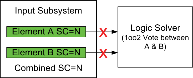
A single systematic failure is likely to affect both elements at the same time
However, if two elements of different technology or elements from two different manufacturers (with different designs) are used, then the chances of both having the same systematic failure at the same time is greatly reduced. An architecture with 1oo2 voting of two different devices with the same SC will increase the overall SC (and the standard allows this to be increased by a maximum of 1; Figure 2 ).
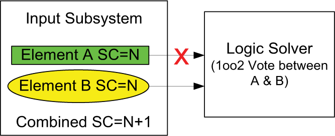
A single systematic failure is likely to affect one element meaning that two systematic failures would be needed to inhibit the safety function
IV. Elements/Components Designed in Accordance with IEC 61508
The standard has requirements for the avoidance of systematic faults (IEC 61508-2, 7.4.6) and requirements for the control of systematic faults (7.4.7). These requirements refer to tables in Annex A and Annex B and define the appropriate measures that should be applied for the SIL level intended for the element/component.
When a group of measures have been applied appropriately for a given SIL level, then the element/component will have a SC of that level. So if all of the measures appropriate for say, SIL 3, have been applied, then SC will equal 3 (SC = 3).
So for SC = 3, we must have met SIL 3 in Tables A.15, A.16, A.17, B1, B2, B3, B4 and B5 of Part 2, and if the element/component contains software/firmware, then Tables A.1–A.10 of Part 3 must also be met. Annexes B and C of Part 3 provide more details on what is required to meet Annex A of Part 3.
Not all of the measures suggested in the tables need to be applied if those specific measures are marked as replaceable. In these instances, at least one measure of a group must be applied, but in practice usually more than one is used.
For example, if we consider Table A16 of Part 2, the first 4 items are marked with ‘M’; this means that it is mandatory to have these measures, and the box also states the effectiveness that must be achieved for the measure, so the first item is M with medium effectiveness. An overview of the required measure can be found in Part 7 (IEC 61508-7) in Section A.8. Guidance on what is classed as high and low effectiveness can be found in Table A.18 of Part 2 where it lists A.8 as a reference.
Items marked as ‘HR’ meaning that the measure is highly recommended, and if the measure is not implemented for some reason, that reason must be documented and justified. Some of the rows are grouped with colour bars at the left-hand side of Table A.16, for example, the eight and ninth rows are grouped together. In these cases, we do not need to implement all rows but must implement at least 1. In the case of rows 8 and 9, we either use idle current principles (row 8) for de-energise to trip applications or if we have an energise-to-action function (row 9), we must apply field loop line monitoring to detect faults in the normally de-energised signal.
For an element to be used in a particular safety function, both the hardware safety integrity (PFD/PFH + HFT) and the SC must meet the requirements for the SIL of that safety function (Safety Instrumented Function in IEC 61511).
Where two or more elements/components are used to provide HFT, the SC can be increased by 1 (IEC 61508-2, 7.4.3.3), provided that the elements are unlikely to have the same systematic faults. So if 1 or 2 levels of HFT is applied (say 2 or 3 transmitters voted 1oo2 or 1oo3) and the function needs to be SIL 3, then the SC of each element/component in parallel must be at least SC = 2 or better and must be of different manufacturers or technologies. Care must be taken to ensure that there is sufficient independence to reduce common cause failure, see Part 2 Clause 7.4.3.4, where the notes associated with the clause include examples of things to be considered.
For components that are claimed to be compliant with the 2010 standard, the safety data should now include the SC listed alongside the single element (simplex) hardware SIL capability. Users need to check both values to ensure that the component is right for the application.
Similar mechanisms need to be applied relating to the software/firmware which are covered in IEC 61508-3, 7.1.2.7. Therefore, to claim a SC of N, both the requirements in IEC 61508-2 and IEC 61508-3 must be met at that level if the element/component uses software in the safety function. If the hardware and software SCs are not the same, then the overall SC achieved is the lower of the two.
A. Example 1
An input subsystem uses two elements (e.g. pressure transmitters) in parallel with a 1oo2 vote. Both transmitters are the same model from the same manufacturer. The manufacturer’s data show that the device is type A, has a safe failure fraction (SFF) >60%, has a PFD that meets an SIL 2 requirement in the intended safety function and has an SC = 2.
When placed in a 1oo2 arrangement, the PFD now meets an SIL 3 requirement, the fault tolerance is increased to 1 meeting the fault tolerance requirements for SIL 3, but both devices are likely to be subject to the same systematic failures, so SC will still be 2 ( Figure 3 ).
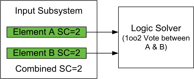
SC: systematic capability.
Therefore, this arrangement will meet the requirements for an SIL 2 application but does not meet the requirement for an SIL 3 application.
B. Example 2
An input subsystem uses two elements (e.g. pressure transmitters) in parallel with a 1oo2 vote. The transmitters are from different manufactures, monitor the process at different points and have different maintenance requirements. The manufacturer’s data show that each device is type A, has a PFD that meets an SIL 2 requirement, has an SFF >60% and has an SC = 2. When placed in a 1oo2 arrangement, the PFD now meets an SIL 3 requirement, the fault tolerance is increased to 1, meeting the requirements for SIL 3, but both devices are unlikely to be subject to the same systematic failures, so SC will now be 3 ( Figure 4 ).
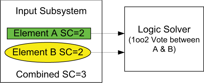
SC: systematic capability.
Therefore, this arrangement will meet the requirements for SIL 3.
V. Routes to SC
In IEC 61508-2 and IEC 61508-3, there are three routes that can be used to achieve SC which are listed in IEC 61508-2, 7.4.2.2 c.
Route 1S. This route covers the requirement for elements and components designed in accordance with IEC 61508 and has been described above.
Route 2S. This route covers components that are used based on proven-in-use IEC 61508-2, 7.4.10 and is discussed below.
Route 3S. This route covers pre-existing software elements and refers directly to IEC 61508-3, 7.4.2.12 and is covered by IEC 61508-3, 7.4.2.12 and 7.4.2.13.
VI. Proven in Use
This is largely based on the experience data of a specific element or component. Experience in using the element/component is used to show that the element/component is unlikely to have any (detected) systematic failures.
Care should be taken when considering proven-in-use because there are many opportunities to introduce systematic failures during the new use of the component. Here are some additional things that need to be considered:
The component actually used in the new implementation may differ from the component considered by the analysis, a component of the same type and manufacture may have been modified over the years. This could be a hardware or software/firmware modification. If the modification was not made in accordance with IEC 61508 Route 1S, then it is difficult to be confident that systematic errors have not been introduced, and there will be little or no previous experience with the new changes; therefore, the previous proven-in-use justification is now invalid. If the changes were carried out in accordance with IEC 61508 Route 1S, then the SIL level of the processes applied during the modification must also be considered in determining the SC of the element/component. If this is carried out correctly, measures to control systematic failures should have been introduced, and hence confidence should be maintained if not increased.
Systematic failures introduced by new use due to differences in the way the element is used, applied or by operator error, all of which may reveal systematic errors that were previously undetected.
We may not have properly identified/recorded or associated systematic failures during the original use.
Systematic faults can often recover when systems are restarted, some examples of these are memory corruption due to errors in the software, or from memory bit flips caused by external events (such as soft error events or electromagnetic interference (EMI)) that only show up under certain conditions, or out of specification temperatures causing the hardware or software to operate incorrectly or cause latch up. Such faults may cause outputs to freeze or cause an output value error. Most of these will disappear when the power is cycled. The question is did the error get detected and attributed correctly for the proven-in-use analysis?
These types of faults are not random hardware faults as such and therefore would not have been taken into account in a PFD/PFH calculation analysis. Let’s consider a loop-powered element or device, for example, a 4–20 mA transmitter. If the output value goes above or below the 4–20 mA range, this can easily be detected and may be recorded as a transmitter fault or a field loop/terminal fault. But in some circumstances, what seems like a field cable/terminal fault could be a systematic fault in the transmitter. Diagnosing a field loop fault may involve breaking the 4–20 mA loop, to insert a current meter, for example. If the transmitter is an intelligent device (incorporates some form of microcontroller), then breaking the loop and reconnecting would have rebooted the controller in the device, so the device would likely have recovered if it had been subject to some types of systematic failure (maybe a software anomaly). The test will now show that the transmitter is working correctly. In this instance, the fault may be logged as a bad connection because the connection was disconnected to insert the meter, and now it has been reconnected and the loop works.
If the test (inserting a current meter) was made during regular maintenance, a systematic fault may not have been detected in the first place due to repowering the device before the test measurement was taken. As you can see, these types of faults may never have happened to the element/component in the previous application, but many of them may be due to external events. An element/component that has been designed in accordance with IEC 61508 Route 1S will have measures to control failures due to these events, but a proven-in-use element/component is unlikely to have the same level of detection and control.
The new element/component may be used in an area where the external events, such as the temperatures, are different (greater or less than) than the original environment or the element is used in a different EMI environment, for example, the route of a cable introduces a new interference frequency or level into the element/component which triggers systematic failures. Without the measures to control systematic failures, care must be taken to ensure that the environment is similar or better than the reference environment.
Although there may be confidence that the element/component itself may have low systematic design failures, the possibility to introduce new systematic failures or stimulate unrevealed systematic failures exists. An engineering judgement needs to be made to decide if the new use is sufficiently similar such that the risk of triggering new (or unrevealed) systematic failures is low compared to the original failure rate.
Therefore, although the element/component has been verified using proven-in-use, measures to control systematic failures in IEC 61508:2010-2 clause 7.4.7 will still need to be implemented at the system/application level, particularly Annex A Table A.16 and Table A.17.
VII. Summary
Systematic integrity has always existed in IEC 61508. SC has been added as a method to describe what level of systematic integrity the element/component has been designed to meet and help guide how systematic integrity should be applied. When an element is designed in accordance with IEC 61508, the design process applies measures to reduce systematic failures, and the product will have measures built in to control systematic failures.
If a proven-in-use route is chosen instead of a purpose designed element/component, the systematic integrity is assumed based on previous experience; however, the product may be missing useful failure detection and control mechanisms that would provide protection against systematic failures introduced in the new application. For example, program sequence monitoring increased interference protection and measures against temperature increase (to mention a few), which will need to be added at the system level or application level.
Footnotes
Funding
This research received no specific grant from any funding agency in the public, commercial or not-for-profit sectors.